EP1209471B1 - Fluid detection method - Google Patents
Fluid detection method Download PDFInfo
- Publication number
- EP1209471B1 EP1209471B1 EP01309580A EP01309580A EP1209471B1 EP 1209471 B1 EP1209471 B1 EP 1209471B1 EP 01309580 A EP01309580 A EP 01309580A EP 01309580 A EP01309580 A EP 01309580A EP 1209471 B1 EP1209471 B1 EP 1209471B1
- Authority
- EP
- European Patent Office
- Prior art keywords
- pressure
- fluid
- container
- determined
- determining
- Prior art date
- Legal status (The legal status is an assumption and is not a legal conclusion. Google has not performed a legal analysis and makes no representation as to the accuracy of the status listed.)
- Expired - Lifetime
Links
- 239000012530 fluid Substances 0.000 title claims abstract description 61
- 238000001514 detection method Methods 0.000 title description 5
- 238000000034 method Methods 0.000 claims abstract description 52
- 239000000523 sample Substances 0.000 claims description 28
- 230000037452 priming Effects 0.000 claims description 7
- 238000009530 blood pressure measurement Methods 0.000 claims description 2
- 230000010354 integration Effects 0.000 claims 2
- 102000004190 Enzymes Human genes 0.000 abstract description 7
- 108090000790 Enzymes Proteins 0.000 abstract description 7
- 238000003018 immunoassay Methods 0.000 abstract description 7
- 230000005499 meniscus Effects 0.000 description 11
- 239000010409 thin film Substances 0.000 description 11
- 238000009826 distribution Methods 0.000 description 4
- 230000035515 penetration Effects 0.000 description 4
- 239000010408 film Substances 0.000 description 3
- 238000012360 testing method Methods 0.000 description 3
- 230000002547 anomalous effect Effects 0.000 description 2
- 230000015572 biosynthetic process Effects 0.000 description 2
- 239000003153 chemical reaction reagent Substances 0.000 description 2
- 238000012545 processing Methods 0.000 description 2
- 230000004044 response Effects 0.000 description 2
- XLYOFNOQVPJJNP-UHFFFAOYSA-N water Substances O XLYOFNOQVPJJNP-UHFFFAOYSA-N 0.000 description 2
- 239000004743 Polypropylene Substances 0.000 description 1
- 230000001668 ameliorated effect Effects 0.000 description 1
- 238000004458 analytical method Methods 0.000 description 1
- 230000001747 exhibiting effect Effects 0.000 description 1
- 239000006260 foam Substances 0.000 description 1
- 239000011521 glass Substances 0.000 description 1
- 238000007654 immersion Methods 0.000 description 1
- 230000006698 induction Effects 0.000 description 1
- 238000002347 injection Methods 0.000 description 1
- 239000007924 injection Substances 0.000 description 1
- 239000007788 liquid Substances 0.000 description 1
- 239000000203 mixture Substances 0.000 description 1
- 238000012544 monitoring process Methods 0.000 description 1
- -1 polypropylene Polymers 0.000 description 1
- 229920001155 polypropylene Polymers 0.000 description 1
- 210000002966 serum Anatomy 0.000 description 1
- 229920001169 thermoplastic Polymers 0.000 description 1
- 239000004416 thermosoftening plastic Substances 0.000 description 1
Images

Classifications
-
- G—PHYSICS
- G01—MEASURING; TESTING
- G01N—INVESTIGATING OR ANALYSING MATERIALS BY DETERMINING THEIR CHEMICAL OR PHYSICAL PROPERTIES
- G01N35/00—Automatic analysis not limited to methods or materials provided for in any single one of groups G01N1/00 - G01N33/00; Handling materials therefor
- G01N35/10—Devices for transferring samples or any liquids to, in, or from, the analysis apparatus, e.g. suction devices, injection devices
-
- Y—GENERAL TAGGING OF NEW TECHNOLOGICAL DEVELOPMENTS; GENERAL TAGGING OF CROSS-SECTIONAL TECHNOLOGIES SPANNING OVER SEVERAL SECTIONS OF THE IPC; TECHNICAL SUBJECTS COVERED BY FORMER USPC CROSS-REFERENCE ART COLLECTIONS [XRACs] AND DIGESTS
- Y10—TECHNICAL SUBJECTS COVERED BY FORMER USPC
- Y10T—TECHNICAL SUBJECTS COVERED BY FORMER US CLASSIFICATION
- Y10T436/00—Chemistry: analytical and immunological testing
- Y10T436/11—Automated chemical analysis
- Y10T436/115831—Condition or time responsive
- Y10T436/116664—Condition or time responsive with automated titrator
-
- Y—GENERAL TAGGING OF NEW TECHNOLOGICAL DEVELOPMENTS; GENERAL TAGGING OF CROSS-SECTIONAL TECHNOLOGIES SPANNING OVER SEVERAL SECTIONS OF THE IPC; TECHNICAL SUBJECTS COVERED BY FORMER USPC CROSS-REFERENCE ART COLLECTIONS [XRACs] AND DIGESTS
- Y10—TECHNICAL SUBJECTS COVERED BY FORMER USPC
- Y10T—TECHNICAL SUBJECTS COVERED BY FORMER US CLASSIFICATION
- Y10T436/00—Chemistry: analytical and immunological testing
- Y10T436/11—Automated chemical analysis
- Y10T436/119163—Automated chemical analysis with aspirator of claimed structure
Definitions
- This invention relates to the to the automated transport of fluids.
- Fluid dispensers are integral components of most automated clinical analyzers.
- U.S. Patent 4,794,085 to Jessop proposes an apparatus and method for detecting sample aspiration in such instruments.
- the device and method employ a pressure sensor to detect the presence of the fluid meniscus in the sample container. When the meniscus is sensed it is assumed that fluid lies beneath and can then be aspirated and dispensed. This method and device have proven useful.
- fluids that are to be aspirated do not always present a meniscus that can reliably be used to determine the location of the surface of the fluid. When this happens, such analyzers can indicate that sufficient fluids have been aspirated when such is not the case. Accordingly, a method for indicating when such a false reading has occurred would be useful.
- a method for determining whether a fluid has been aspirated as set forth in the accompanying claim 1.
- pressure readings are taken during a slow aspirate process and during a priming process.
- Reference pressure measurement also occurs after priming.
- Two differences are determined, one is the difference between pressure readings during slow aspirate and the reference pressure and the other is the difference between the reference pressure and pressure readings during prime. If either is less than a predetermined threshold then an error message is communicated.
- the pressure reading during slow aspirate is a trough reading and the pressure reading prime is a prime reading where trough and peak values may be statistical (e.g. numerically averaged values) at or near the trough and peak readings.
- the threshold is determined statistically.
- a parameter such as CpK can be used to calculate the effectiveness that the film of fluid will be detected without a high frequency of false positive.
- the invention is useful in any dispensing apparatus or method in which a fluid is aspirated into a delivery vessel such as a sample probe in a clinical analyzer.
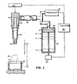
- FIG. 1 A portion of a preferred dispensing apparatus is illustrated in FIG. 1.
- a plurality of sample containers 20 is provided in a tray (not shown), which also supports removable, disposable dispensing containers 30.
- the containers 30 have a larger aperture 32 at one end to mate with the probe thus forming the tip of the probe when mated. They also have a smaller aperture 34 at the opposite end for aspirating and dispensing.
- a probe 40 is mounted for vertical and horizontal movement on a frame (not shown), such movement being provided respectively by a motor 44 and gear (not shown), and by a car (not shown) carrying the probe 40 horizontally on rails (not shown). The combined movement of the car and probe is effective to carry the probe vertically within the plane of the paper in FIG. 1.
- a pressure line 52 provides a partial vacuum or a partial pressure, relative to atmospheric pressure, to a dispensing container 30 picked up by the probe.
- the pressure or vacuum is provided by means such as a piston as described in U.S. Patent 4,794,085,
- a pressure transducer as described in the '085 patent is used to sense the pressure in container 30, for example to determine when proper dispensing of the fluid out of container 30 occurs.
- An appropriate controller 80 is provided to coordinate the actuation of the motors that drive the pistons 60 or other devices that adjust pressure in the probe in response to conditions sensed by the transducer.
- the controller generally comprises a microprocessor.
- aspiration of fluid in container 30 is conducted by lowering the probe 40 so that container 30 is in fluid contact with fluid in container 20. A negative pressure is then induced via pressure line 52, drawing fluid into container 30 in the manner known in the art. Probe 40 descends as needed to keep pace with the falling meniscus level. The process thus far described is referred to as “fast aspirate” and, as is indicated by its moniker, can be conducted as rapidly as the mechanics of the system will permit. In the typical fast aspirate step used in the preferred automated enzyme immunoassay analyzer, about 30 ⁇ l of sample is aspirated into container 30.
- This volume is the combination of "dead volume in the tip" and the prime volume and is the same for all dispensed volumes in the examples of this application.
- the recitation of this volume in no way limits the scope of the invention and is merely provided for exemplary purposes.
- transducer 70 Throughout fast aspirate signals are again produced by transducer 70 and each such signal is compared to another base pressure reading. The process is interrupted and an error message is generated if the signal is less than a predetermined value empirically determined to indicate that insufficient fluid has been aspirated. Such an event would occur, for example, when a bubble that would interfere with the subsequent use of the fluid has been aspirated.
- slow aspirate In the typical slow aspirate step used in the preferred automated enzyme immunoassay analyzer, about 10 ⁇ l of sample is aspirated back into container 30 (this volume is equivalent to the volume to be dispensed). As noted above, the recitation of this volume in no way limits the scope of the invention and is merely provided for exemplary purposes.
- Pressure readings are taken during the slow aspirate phase. Preferably, a number of such readings are taken from which a statistically representative value is determined. This value is determined at or near the trough of the slow aspirate signal. This value is referred to as level B. Similarly, a number of pressure readings are taken during the prime phase from which a statistically relevant value is determined. This value is determined at or near the peak of the prime signal and is referred to as level A. A reference pressure value is also determined. This value is referred to as level C.
- the reference value is preferably determined by taking a large number of pressure readings after the end of priming (preferably, the time at which the pump stops during the prime cycle). Preferably, more than 50 such readings are taken, more preferably, more than 100 readings are taken, and most preferably 130-140 readings are taken. An arithmetic average of these readings is then used as the reference value.
- Alternative methods for establishing the reference value include using the minimum pressure reading taken over the course of a number of readings or by integrating a plot of pressure readings taken over time during some step in the process other than slow aspirate or prime steps.
- the reference value may also be obtained via moving average or by a combination of moving average and any of the aforementioned methods.
- Level A is preferably determined as follows.
- the peak pressure during the prime step is determined.
- Preferably at least two additional readings are taken, one just prior to the peak pressure and another just after the peak pressure are also taken.
- the arithmetic average of these readings is then Level A.
- the readings just before and just after the peak pressure readings are taken at intervals of about 500-750 milliseconds before/after the peak pressure readings.
- Alternative methods for determining Level A include using the maximum pressure reading taken over the course of a number of readings or by integrating a plot of pressure readings taken over time during the prime step.
- Level A may also be obtained via moving average or by a combination of moving average and any of the aforementioned methods.
- the threshold value to which Diff 1 and Diff 2 are compared is determined as follows. True positive (sample volume accurately measured for sample that is present) and true negative distributions (the absence of sample volume accurately measured as absent) are constructed from pressure traces using direct observations (multiple pressure readings during the relevant cycles). Arithmetic mean and standard deviation values for each distribution are determined.
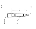
- container 30 is made from injection moldable thermoplastic such as polypropylene and has the geometry shown in Fig. 2.
- Fluid carrying portion 30 is about 30 mm in length (measured according to dimension 30d) with an outside diameter ranging from 1.5 mm at its narrowest to 6.8 mm at its widest.
- Smallest aperture 34 has a diameter of about 0.5 mm with a cylindrical portion 32 that is about 3 mm in length.
- the process for determining threshold values described above yields a threshold value of 0.01 to 2 kPa.
- the cutoff is set at about 0.065 kPa. Establishing threshold values when using containers of other geometries and dimensions is readily accomplished with routine experimentation according the method described above.
- the thin film fluid detection (based on this data when the thin film bubble was present) was also shown to be independent of fluid type and aspirate volume.
Abstract
Description
- This invention relates to the to the automated transport of fluids.
- Fluid dispensers are integral components of most automated clinical analyzers. U.S. Patent 4,794,085 to Jessop proposes an apparatus and method for detecting sample aspiration in such instruments. The device and method employ a pressure sensor to detect the presence of the fluid meniscus in the sample container. When the meniscus is sensed it is assumed that fluid lies beneath and can then be aspirated and dispensed. This method and device have proven useful. However, fluids that are to be aspirated do not always present a meniscus that can reliably be used to determine the location of the surface of the fluid. When this happens, such analyzers can indicate that sufficient fluids have been aspirated when such is not the case. Accordingly, a method for indicating when such a false reading has occurred would be useful.
- In EP-A-0658769, there is disclosed a method for detecting leakage of fluid from a fluid container. The method comprises: as a first step, comparing a detected pressure within the container with atmospheric pressure when fluid has been aspirated into the container, as a second step, comparing the pressure within the container with the pressure at a later point in time, and, as a third step, monitoring the pressure as liquid is dispensed from the container.
- According to the invention, there is provided a method for determining whether a fluid has been aspirated, as set forth in the accompanying
claim 1. Thus, in the method, pressure readings are taken during a slow aspirate process and during a priming process. Reference pressure measurement also occurs after priming. Two differences are determined, one is the difference between pressure readings during slow aspirate and the reference pressure and the other is the difference between the reference pressure and pressure readings during prime. If either is less than a predetermined threshold then an error message is communicated. - In a further embodiment of the invention, the pressure reading during slow aspirate is a trough reading and the pressure reading prime is a prime reading where trough and peak values may be statistical (e.g. numerically averaged values) at or near the trough and peak readings.
- In yet a further embodiment of the invention, the threshold is determined statistically. In this embodiment, a parameter such as CpK can be used to calculate the effectiveness that the film of fluid will be detected without a high frequency of false positive.
-
- FIG. 1 is a fragmentary perspective view of a dispensing apparatus with which the method of the invention can be practiced;
- FIG. 2 is a perspective view of fluid containers that are useful in the practice of the invention; and
- FIG. 3 is a flow chart for programming the controller of the described apparatus to carry out the invention.
- The invention is useful in any dispensing apparatus or method in which a fluid is aspirated into a delivery vessel such as a sample probe in a clinical analyzer.
- Terms such as "up", "down", "lower", "vertical", "horizontal", and "bottom", as used herein refer to the orientation of parts when the apparatus is positioned in its customary position of use.
- A portion of a preferred dispensing apparatus is illustrated in FIG. 1. A plurality of
sample containers 20 is provided in a tray (not shown), which also supports removable,disposable dispensing containers 30. Thecontainers 30 have alarger aperture 32 at one end to mate with the probe thus forming the tip of the probe when mated. They also have asmaller aperture 34 at the opposite end for aspirating and dispensing. Aprobe 40 is mounted for vertical and horizontal movement on a frame (not shown), such movement being provided respectively by amotor 44 and gear (not shown), and by a car (not shown) carrying theprobe 40 horizontally on rails (not shown). The combined movement of the car and probe is effective to carry the probe vertically within the plane of the paper in FIG. 1. - A
pressure line 52 provides a partial vacuum or a partial pressure, relative to atmospheric pressure, to a dispensingcontainer 30 picked up by the probe. The pressure or vacuum is provided by means such as a piston as described in U.S. Patent 4,794,085, - A pressure transducer as described in the '085 patent is used to sense the pressure in
container 30, for example to determine when proper dispensing of the fluid out ofcontainer 30 occurs. - An
appropriate controller 80 is provided to coordinate the actuation of the motors that drive thepistons 60 or other devices that adjust pressure in the probe in response to conditions sensed by the transducer. The controller generally comprises a microprocessor. - The described apparatus is used as follows to detect the penetration of the fluid meniscus M, by the
aperture 34 of container 30: - a) assume the total distance from
aperture 34 to a point that will always penetrate the fluid (the minimum fill) is initially dimension Y, - b) while
container 30 is still at atmospheric pressure, a base pressure value is established; this is done by generating a signal by thepressure transducer 70 before aspiration of fluid is begun, - c)
container 30, positioned on the end ofprobe 40, is lowered to position Y (and then lower as indicated in d) below, if necessary); throughout this process, signals are again produced bytransducer 70, and those signals are compared to the base pressure signal previously generated; if there is no difference greater than a predetermined amount, then the fluid meniscus M still has not been penetrated, - d) if the fluid meniscus has not been penetrated, step c) is repeated until either a transducer signal is generated at a new level that exceeds the predetermined value, thus indicating the penetration of meniscus, or the advancement of the probe would exceed a safety factor (a level beyond which the
container 30 may crash into the container 20); if the safety factor is exceeded or the pressure differences do not exceed the predetermined amount, fluid aspiration is not conducted for that sample and an error message is generated. - When the transducer signal indicates fluid penetration, aspiration of fluid in
container 30 is conducted by lowering theprobe 40 so thatcontainer 30 is in fluid contact with fluid incontainer 20. A negative pressure is then induced viapressure line 52, drawing fluid intocontainer 30 in the manner known in the art. Probe 40 descends as needed to keep pace with the falling meniscus level. The process thus far described is referred to as "fast aspirate" and, as is indicated by its moniker, can be conducted as rapidly as the mechanics of the system will permit. In the typical fast aspirate step used in the preferred automated enzyme immunoassay analyzer, about 30 µl of sample is aspirated intocontainer 30. This volume is the combination of "dead volume in the tip" and the prime volume and is the same for all dispensed volumes in the examples of this application. Of course, the recitation of this volume in no way limits the scope of the invention and is merely provided for exemplary purposes. - Throughout fast aspirate signals are again produced by
transducer 70 and each such signal is compared to another base pressure reading. The process is interrupted and an error message is generated if the signal is less than a predetermined value empirically determined to indicate that insufficient fluid has been aspirated. Such an event would occur, for example, when a bubble that would interfere with the subsequent use of the fluid has been aspirated. - Following the fast aspirate step, all of the previous steps that ensure that meniscus penetration and fluid aspiration are appropriate are again conducted and another predetermined volume of fluid is aspirated into
container 30. This process is referred to as "slow aspirate". In the typical slow aspirate step used in the preferred automated enzyme immunoassay analyzer, about 10 µl of sample is aspirated back into container 30 (this volume is equivalent to the volume to be dispensed). As noted above, the recitation of this volume in no way limits the scope of the invention and is merely provided for exemplary purposes. - Since the slow aspirate process is conducted by the induction of a negative pressure, a convex meniscus is formed in the upper portion of
container 30. This is undesirable and is ameliorated by reducing the negative pressure used to contain the fluid incontainer 30 so that a small predetermined amount of fluid is expelled back intocontainer 20. This process is referred to as "priming". In the typical priming step used in the preferred automated enzyme immunoassay analyzer, about 10 µl of sample is primed back intocontainer 20. Here too, the recitation of this volume in no way limits the scope of the invention and is merely provided for exemplary purposes. - The process thus far described is well known in the art and is commonly used in commercial clinical analyzers such as automated enzyme immunoassay analyzers. In such applications aspirated fluid is subsequently dispensed in reaction vessels for further combination with, for example, other reagents, in such applications.
- During the previously described process it sometimes happens that a thin film of fluid is formed in
container 30 above the meniscus of the fluid that is to be aspirated. The formation of such a film can be problematic. That is, the pressure sensing methods described can detect the film and determine that it has a different response to pressure than does air. This can lead to a result that indicates that a sufficient volume of fluid has been aspirated even when it has not. It is important to differentiate between a thin film of fluid above the primary volume of fluid and bubbles or foam above the fluid. Each produces a different pressure signature and needs to be detected differently. Employment of the following method avoids this outcome. - Pressure readings are taken during the slow aspirate phase. Preferably, a number of such readings are taken from which a statistically representative value is determined. This value is determined at or near the trough of the slow aspirate signal. This value is referred to as level B. Similarly, a number of pressure readings are taken during the prime phase from which a statistically relevant value is determined. This value is determined at or near the peak of the prime signal and is referred to as level A. A reference pressure value is also determined. This value is referred to as level C.
- Two different difference values are then determined. Difference value 1 (Diff 1) is calculated by subtracting level B from level C. Difference value 2 (Diff 2) is calculated by subtracting level C from level A. If either
Diff 1 orDiff 2 is less than a predetermined threshold thencontainer 30 contains a thin film that can obscure the accurate measure of the volume aspirated. In such a case, the remainder of the aspirated fluid incontainer 30 is discarded and a message is generated indicating that such events have occurred. The sample can be dispensed into a vessel that would have undergone subsequent processing such as mixture with reagents but no such subsequent processing need be conducted. This process is also shown graphically in the flow chart of Fig. 3. - The reference value is preferably determined by taking a large number of pressure readings after the end of priming (preferably, the time at which the pump stops during the prime cycle). Preferably, more than 50 such readings are taken, more preferably, more than 100 readings are taken, and most preferably 130-140 readings are taken. An arithmetic average of these readings is then used as the reference value. Alternative methods for establishing the reference value include using the minimum pressure reading taken over the course of a number of readings or by integrating a plot of pressure readings taken over time during some step in the process other than slow aspirate or prime steps. The reference value may also be obtained via moving average or by a combination of moving average and any of the aforementioned methods.
- Level B is preferably determined as follows. A number of pressure readings (preferably 5 to 20, more preferably 6 to17, and most preferably 10 to 17 readings) are taken during the slow aspirate cycle. The end of the cycle occurs when the pump stops during the slow aspirate step. An arithmetic average of these readings is then Level B. Alternative methods for determining level Binclude using the minimum pressure reading taken over the course of a number of readings or by integrating a plot of pressure readings taken over time during the slow aspirate step. Level B may also be obtained via moving average or by a combination of moving average and any of the aforementioned methods.
- Level A is preferably determined as follows. The peak pressure during the prime step is determined. Preferably at least two additional readings are taken, one just prior to the peak pressure and another just after the peak pressure are also taken. The arithmetic average of these readings is then Level A. Preferably, the readings just before and just after the peak pressure readings are taken at intervals of about 500-750 milliseconds before/after the peak pressure readings. Alternative methods for determining Level A include using the maximum pressure reading taken over the course of a number of readings or by integrating a plot of pressure readings taken over time during the prime step. Level A may also be obtained via moving average or by a combination of moving average and any of the aforementioned methods.
- The threshold value to which
Diff 1 andDiff 2 are compared is determined as follows.
True positive (sample volume accurately measured for sample that is present) and true negative distributions (the absence of sample volume accurately measured as absent) are constructed from pressure traces using direct observations (multiple pressure readings during the relevant cycles). Arithmetic mean and standard deviation values for each distribution are determined. - To account for differences in atmospheric pressure from place to place (i.e., due to differences in altitude), distributions for true positive and true negative events can be shifted by a constant factor determined empirically under different pressure conditions. This can be determined by use of the following well-known relationship:

- ΔP2
- = Pressure at new altitude (atm)
- ΔP0
- = Pressure at reference altitude (atm)
- M
- = Molecular Weight of the gas (g / mole)
- g
- = 980.665 cm/sec2
- z
- = Altitude change (cm)
- R
- = 8.3144 x 10⁷ (ergs / deg mole)
- T
- = Temperature (degrees K).
- Upper and lower pressure limits can be then be established using the mean and standard deviation determinations. In the preferred method, a Process Capability Index (CpK) value is used to adequately protect against both false negatives and false positives. This index represents the ability of the detection algorithm to discriminate between anomalous and non-anomalous events on a short-term basis. It is a tool for considering the spread and mean shift of a process that should be confined between upper and lower limits in processes exhibiting a normal distribution of the spread of data. CpK values are determined according to methods well known in the art. It is preferred that the Cpk is determined according to the following relationship:

- USL
- is the upper specification limit
- LSL
- is the lower specification limit
- µ
- is the mean of the data
- σ
- is the standard deviation of the data
- In the most preferred embodiment of this invention,
container 30 is made from injection moldable thermoplastic such as polypropylene and has the geometry shown in Fig. 2.Fluid carrying portion 30 is about 30 mm in length (measured according todimension 30d) with an outside diameter ranging from 1.5 mm at its narrowest to 6.8 mm at its widest.Smallest aperture 34 has a diameter of about 0.5 mm with acylindrical portion 32 that is about 3 mm in length. When using such containers, the process for determining threshold values described above yields a threshold value of 0.01 to 2 kPa. Preferably, the cutoff is set at about 0.065 kPa. Establishing threshold values when using containers of other geometries and dimensions is readily accomplished with routine experimentation according the method described above. - Testing was done on four ECi automated enzyme immunoassay analyzers commercially available from Ortho Clinical Diagnostics, Rochester, N.Y. Containers for aspirating fluid were the type commercially sold as disposables for use with the analyzers and conform to the preferred embodiment described above.
- Four different fluid volumes were aspirated during slow aspirate: 10, 20, 25 and µl with an attempt at creating four thin film bubbles at each volume on each analyzer using 4 centipoise and normal serum as the fluid in the tubes. This test was done using 13mm glass primary collection tubes. Testing was also done using water in a 2ml cup with the cup support set to the lowest tolerance to simulate worst-case tip immersion. This was done to create a condition simulating very low pressure signal for slow aspirate and prime without a thin film of fluid present in the tube or cup.
- Across the four analyzers tested there were 88 thin film events observed. All of the thin film events were detected with the new method (with the threshold set to 0.065 kPa). None of the "non-thin film" aspirates (n=229) were falsely flagged as an error.
- The robustness of the process was tested by conducting the same process by aspirating and priming low viscosity fluid (water). This analysis was done a second time with eight high pressure outliers removed from the data set. These values inflate the standard deviation but did not increase the likelihood that a false error code occurred.
- No false positive or negative results were produced across the fluid types and four analyzers tested.
- The thin film fluid detection (based on this data when the thin film bubble was present) was also shown to be independent of fluid type and aspirate volume.
Claims (10)
- A method for determining whether a fluid has been properly aspirated into a fluid container (30) comprising:a) determining the pressure inside the container (30) during initial aspiration of the fluid;b) determining the pressure inside the container (30) while dispensing a portion of the fluid;c) determining the pressure inside the container (30) at some time other than during steps a) and b) to establish a reference pressure;d) determining the difference between the value attained in step a) and the reference pressure;e) determining the difference between the reference pressure and the value attained in step b); andf) indicating that the fluid has not been properly aspirated if the absolute values obtained in step d) or step e) are less than a predetermined threshold.
- The method of claim 1 wherein the reference pressure measurement occurs after priming.
- The method of claim 1 wherein the pressure of step a) is an average of the lowest values recorded during such step.
- The method of claim 1 wherein the pressure reading of step b) is the average of highest values recorded during such step.
- The method of claim 1 wherein the threshold is determined statistically as the CpK that is acceptable for a given false positive and/or false negative rate.
- The method of claim 5 wherein the threshold value is 0.01 to 2 kPa.
- The method of claim 6 wherein the threshold value is 0.065 kPa.
- The method of claim 1 wherein the pressure of step a) is determined by recording a minimum, a value determined by integration over time, a moving average, or a combination thereof.
- The method of claim 2 wherein the pressure of step b) is determined by recording a maximum, a value determined by integration over time, a moving average, or a combination thereof.
- The method of any preceding claim, carried out in an apparatus for aspirating and dispensing fluid which includes: a probe(40) for removably mounting the container (30), which has an aspirating and dispensing aperture (34); and a pressurizing device (60, 62) fluidly connected to said probe (40) for generating a pressure differential relative to atmospheric pressure, effective to aspirate or dispense fluid into or from the mounted container (30).
Applications Claiming Priority (2)
| Application Number | Priority Date | Filing Date | Title |
|---|---|---|---|
| US09/711,483 US6484556B1 (en) | 2000-11-13 | 2000-11-13 | Thin film detection during fluid aspiration |
| US711483 | 2000-11-13 |
Publications (3)
| Publication Number | Publication Date |
|---|---|
| EP1209471A2 EP1209471A2 (en) | 2002-05-29 |
| EP1209471A3 EP1209471A3 (en) | 2004-04-14 |
| EP1209471B1 true EP1209471B1 (en) | 2006-07-26 |
Family
ID=24858259
Family Applications (1)
| Application Number | Title | Priority Date | Filing Date |
|---|---|---|---|
| EP01309580A Expired - Lifetime EP1209471B1 (en) | 2000-11-13 | 2001-11-13 | Fluid detection method |
Country Status (6)
| Country | Link |
|---|---|
| US (1) | US6484556B1 (en) |
| EP (1) | EP1209471B1 (en) |
| AT (1) | ATE334399T1 (en) |
| AU (1) | AU780959B2 (en) |
| CA (1) | CA2361798C (en) |
| DE (1) | DE60121703T2 (en) |
Families Citing this family (13)
| Publication number | Priority date | Publication date | Assignee | Title |
|---|---|---|---|---|
| US6579724B2 (en) * | 2001-09-13 | 2003-06-17 | First Ten Angstroms | Dispensing method and apparatus for dispensing very small quantities of fluid |
| US7543720B2 (en) * | 2003-05-05 | 2009-06-09 | The Lee Company | Method and apparatus for dispensing small volumes of fluid |
| US7222526B2 (en) | 2004-06-17 | 2007-05-29 | Ortho-Clinical Diagnostics, Inc | Liquid measurements using capacitive monitoring |
| CA2623241A1 (en) | 2005-04-21 | 2006-11-02 | Celerus Diagnostics, Inc. | Parallel processing fluidic method and apparatus for automated rapid immunohistochemistry |
| US8012766B2 (en) | 2005-08-01 | 2011-09-06 | Ortho-Clinical Diagnostics, Inc. | Prediction of aspirated volume of a liquid |
| DE102005060862B3 (en) * | 2005-12-20 | 2007-06-28 | Stratec Biomedical Systems Ag | Assessing dosing performance of pipette connected to metering pump comprises determining pressure-time plot and comparing it with target plot of pump speed or power |
| US8703492B2 (en) | 2007-04-06 | 2014-04-22 | Qiagen Gaithersburg, Inc. | Open platform hybrid manual-automated sample processing system |
| US7985375B2 (en) | 2007-04-06 | 2011-07-26 | Qiagen Gaithersburg, Inc. | Sample preparation system and method for processing clinical specimens |
| US9953141B2 (en) | 2009-11-18 | 2018-04-24 | Becton, Dickinson And Company | Laboratory central control unit method and system |
| US8307697B2 (en) | 2010-04-14 | 2012-11-13 | Ortho-Clinical Diagnostics, Inc. | Method for estimating viscosity |
| CA2766735C (en) | 2011-02-07 | 2020-06-02 | Ortho-Clinical Diagnostics, Inc. | Determining conditions in centrifuged blood using measured pressure |
| JP5865633B2 (en) * | 2011-09-01 | 2016-02-17 | 株式会社日立ハイテクノロジーズ | Automatic analyzer |
| JP6651448B2 (en) | 2013-12-06 | 2020-02-19 | オーソ−クリニカル・ダイアグノスティックス・インコーポレイテッドOrtho−Clinical Diagnostics, Inc. | Assay device with wash port |
Family Cites Families (19)
| Publication number | Priority date | Publication date | Assignee | Title |
|---|---|---|---|---|
| US4794085A (en) | 1984-07-19 | 1988-12-27 | Eastman Kodak Company | Apparatus and method for detecting liquid penetration by a container used for aspirating and dispensing the liquid |
| JPS6264912A (en) | 1985-09-17 | 1987-03-24 | Minoru Atake | Distributive injection apparatus |
| JPS6375565A (en) * | 1986-09-18 | 1988-04-05 | Toshiba Corp | Sampling monitor |
| EP0341438A3 (en) * | 1988-05-13 | 1990-11-28 | Abbott Laboratories | Pneumatic sensing system |
| US5143849A (en) * | 1991-03-21 | 1992-09-01 | Eastman Kodak Company | Tip to surface spacing for optimum dispensing controlled by a detected pressure change in the tip |
| JP2725917B2 (en) * | 1991-10-04 | 1998-03-11 | アロカ株式会社 | Blood sample dispensing method |
| JP2725940B2 (en) * | 1992-03-03 | 1998-03-11 | アロカ株式会社 | Dispensing device |
| JP2578296B2 (en) * | 1992-09-02 | 1997-02-05 | アロカ株式会社 | Leak detection method in automatic dispensing equipment |
| JP3318629B2 (en) * | 1993-06-18 | 2002-08-26 | ソニー株式会社 | Liquid suction / discharge device and method |
| US5540081A (en) * | 1993-08-31 | 1996-07-30 | Abbott Laboratories | Pipetting apparatus with clot detection |
| US5814275A (en) * | 1995-02-15 | 1998-09-29 | Akzo Nobel N.V. | Obstruction detector for a fluid flow line of a medical laboratory instrument |
| US5537880A (en) * | 1995-06-07 | 1996-07-23 | Abbott Laboratories | Automatic pipetting apparatus with leak detection and method of detecting a leak |
| US6158269A (en) * | 1995-07-13 | 2000-12-12 | Bayer Corporation | Method and apparatus for aspirating and dispensing sample fluids |
| US5750881A (en) * | 1995-07-13 | 1998-05-12 | Chiron Diagnostics Corporation | Method and apparatus for aspirating and dispensing sample fluids |
| US5723795A (en) * | 1995-12-14 | 1998-03-03 | Abbott Laboratories | Fluid handler and method of handling a fluid |
| US6083762A (en) * | 1996-05-31 | 2000-07-04 | Packard Instruments Company | Microvolume liquid handling system |
| US6121049A (en) | 1997-12-05 | 2000-09-19 | Bayer Corporation | Method of verifying aspirated volume in automatic diagnostic system |
| US6060320A (en) | 1997-12-05 | 2000-05-09 | Bayer Corporation | Method of verifying aspirated volume in automatic diagnostic system |
| US6022747A (en) * | 1998-07-10 | 2000-02-08 | Bayer Corporation | Blood clot detector |
-
2000
- 2000-11-13 US US09/711,483 patent/US6484556B1/en not_active Expired - Lifetime
-
2001
- 2001-11-02 AU AU87310/01A patent/AU780959B2/en not_active Ceased
- 2001-11-09 CA CA002361798A patent/CA2361798C/en not_active Expired - Fee Related
- 2001-11-13 EP EP01309580A patent/EP1209471B1/en not_active Expired - Lifetime
- 2001-11-13 AT AT01309580T patent/ATE334399T1/en not_active IP Right Cessation
- 2001-11-13 DE DE60121703T patent/DE60121703T2/en not_active Expired - Lifetime
Also Published As
| Publication number | Publication date |
|---|---|
| CA2361798A1 (en) | 2002-05-13 |
| EP1209471A3 (en) | 2004-04-14 |
| DE60121703T2 (en) | 2007-08-02 |
| AU780959B2 (en) | 2005-04-28 |
| US6484556B1 (en) | 2002-11-26 |
| AU8731001A (en) | 2002-05-16 |
| ATE334399T1 (en) | 2006-08-15 |
| DE60121703D1 (en) | 2006-09-07 |
| CA2361798C (en) | 2010-01-05 |
| EP1209471A2 (en) | 2002-05-29 |
Similar Documents
| Publication | Publication Date | Title |
|---|---|---|
| EP1209471B1 (en) | Fluid detection method | |
| TWI422801B (en) | Method of detecting dispensed quantity and liquid draw monitoring type dispensing device | |
| JP4686100B2 (en) | How to check the integrity of fluid movement | |
| US8475740B2 (en) | Liquid dispensing apparatus | |
| EP1422528B1 (en) | Automatic analyzer | |
| JP2001021572A (en) | Method for confirming aspirated volume of fluid | |
| JP5899075B2 (en) | Automatic analyzer | |
| EP1761755B1 (en) | Method for aspiration of a liquid sample | |
| EP2525230A1 (en) | Automatic analyzing device | |
| FI85190B (en) | AVKAENNARE FOER VAETSKENIVAON AVSEDD FOER ANVAENDNING I EN AUTOMATISK ANORDNING FOER FRAMSTAELLNING AV IMMUNOLOGISKA AVOSOS DOSERINGAR. | |
| EP3058352B1 (en) | Methods and apparatus for measuring aspiration pressure | |
| CN106353519A (en) | Method for pipetting liquids in an automated analysis apparatus | |
| JP2004271266A (en) | Dispensing device and autoanalyzer using the same | |
| JPWO2015111442A1 (en) | Automatic analyzer | |
| EP0042337B1 (en) | Method and apparatus for metering biological fluids | |
| JP4045211B2 (en) | Automatic analyzer | |
| US7361509B2 (en) | Dynamic metered fluid volume determination method and related apparatus | |
| EP1812163B1 (en) | Method for checking the condition of a sample when metering liquid | |
| WO2020195500A1 (en) | Automatic analysis apparatus | |
| JPH05306973A (en) | Method and device for dispensing liquid | |
| JP2592837B2 (en) | Automatic chemical analyzer | |
| JP2003254983A (en) | Level detection apparatus and automatic analyzer using the same | |
| JP2688163B2 (en) | Dispensing device | |
| JPH09274047A (en) | Biochemclcal automatic analyzer dispensing apparatus for medical practice | |
| JPH0450770A (en) | Remaining liquid check device |
Legal Events
| Date | Code | Title | Description |
|---|---|---|---|
| PUAI | Public reference made under article 153(3) epc to a published international application that has entered the european phase |
Free format text: ORIGINAL CODE: 0009012 |
|
| AK | Designated contracting states |
Kind code of ref document: A2 Designated state(s): AT BE CH CY DE DK ES FI FR GB GR IE IT LI LU MC NL PT SE TR |
|
| AX | Request for extension of the european patent |
Free format text: AL;LT;LV;MK;RO;SI |
|
| PUAL | Search report despatched |
Free format text: ORIGINAL CODE: 0009013 |
|
| AK | Designated contracting states |
Kind code of ref document: A3 Designated state(s): AT BE CH CY DE DK ES FI FR GB GR IE IT LI LU MC NL PT SE TR |
|
| AX | Request for extension of the european patent |
Extension state: AL LT LV MK RO SI |
|
| 17P | Request for examination filed |
Effective date: 20040924 |
|
| AKX | Designation fees paid |
Designated state(s): AT BE CH CY DE DK ES FI FR GB GR IE IT LI LU MC NL PT SE TR |
|
| GRAP | Despatch of communication of intention to grant a patent |
Free format text: ORIGINAL CODE: EPIDOSNIGR1 |
|
| GRAS | Grant fee paid |
Free format text: ORIGINAL CODE: EPIDOSNIGR3 |
|
| GRAA | (expected) grant |
Free format text: ORIGINAL CODE: 0009210 |
|
| AK | Designated contracting states |
Kind code of ref document: B1 Designated state(s): AT BE CH CY DE DK ES FI FR GB GR IE IT LI LU MC NL PT SE TR |
|
| PG25 | Lapsed in a contracting state [announced via postgrant information from national office to epo] |
Ref country code: IT Free format text: LAPSE BECAUSE OF FAILURE TO SUBMIT A TRANSLATION OF THE DESCRIPTION OR TO PAY THE FEE WITHIN THE PRESCRIBED TIME-LIMIT;WARNING: LAPSES OF ITALIAN PATENTS WITH EFFECTIVE DATE BEFORE 2007 MAY HAVE OCCURRED AT ANY TIME BEFORE 2007. THE CORRECT EFFECTIVE DATE MAY BE DIFFERENT FROM THE ONE RECORDED. Effective date: 20060726 Ref country code: BE Free format text: LAPSE BECAUSE OF FAILURE TO SUBMIT A TRANSLATION OF THE DESCRIPTION OR TO PAY THE FEE WITHIN THE PRESCRIBED TIME-LIMIT Effective date: 20060726 Ref country code: FI Free format text: LAPSE BECAUSE OF FAILURE TO SUBMIT A TRANSLATION OF THE DESCRIPTION OR TO PAY THE FEE WITHIN THE PRESCRIBED TIME-LIMIT Effective date: 20060726 Ref country code: AT Free format text: LAPSE BECAUSE OF FAILURE TO SUBMIT A TRANSLATION OF THE DESCRIPTION OR TO PAY THE FEE WITHIN THE PRESCRIBED TIME-LIMIT Effective date: 20060726 Ref country code: NL Free format text: LAPSE BECAUSE OF FAILURE TO SUBMIT A TRANSLATION OF THE DESCRIPTION OR TO PAY THE FEE WITHIN THE PRESCRIBED TIME-LIMIT Effective date: 20060726 |
|
| REG | Reference to a national code |
Ref country code: GB Ref legal event code: FG4D |
|
| REG | Reference to a national code |
Ref country code: CH Ref legal event code: EP |
|
| REG | Reference to a national code |
Ref country code: IE Ref legal event code: FG4D |
|
| REF | Corresponds to: |
Ref document number: 60121703 Country of ref document: DE Date of ref document: 20060907 Kind code of ref document: P |
|
| REG | Reference to a national code |
Ref country code: CH Ref legal event code: NV Representative=s name: E. BLUM & CO. PATENTANWAELTE |
|
| PG25 | Lapsed in a contracting state [announced via postgrant information from national office to epo] |
Ref country code: SE Free format text: LAPSE BECAUSE OF FAILURE TO SUBMIT A TRANSLATION OF THE DESCRIPTION OR TO PAY THE FEE WITHIN THE PRESCRIBED TIME-LIMIT Effective date: 20061026 Ref country code: DK Free format text: LAPSE BECAUSE OF FAILURE TO SUBMIT A TRANSLATION OF THE DESCRIPTION OR TO PAY THE FEE WITHIN THE PRESCRIBED TIME-LIMIT Effective date: 20061026 |
|
| PG25 | Lapsed in a contracting state [announced via postgrant information from national office to epo] |
Ref country code: ES Free format text: LAPSE BECAUSE OF FAILURE TO SUBMIT A TRANSLATION OF THE DESCRIPTION OR TO PAY THE FEE WITHIN THE PRESCRIBED TIME-LIMIT Effective date: 20061106 |
|
| PG25 | Lapsed in a contracting state [announced via postgrant information from national office to epo] |
Ref country code: IE Free format text: LAPSE BECAUSE OF NON-PAYMENT OF DUE FEES Effective date: 20061113 |
|
| PG25 | Lapsed in a contracting state [announced via postgrant information from national office to epo] |
Ref country code: MC Free format text: LAPSE BECAUSE OF NON-PAYMENT OF DUE FEES Effective date: 20061130 |
|
| PG25 | Lapsed in a contracting state [announced via postgrant information from national office to epo] |
Ref country code: PT Free format text: LAPSE BECAUSE OF FAILURE TO SUBMIT A TRANSLATION OF THE DESCRIPTION OR TO PAY THE FEE WITHIN THE PRESCRIBED TIME-LIMIT Effective date: 20061226 |
|
| NLV1 | Nl: lapsed or annulled due to failure to fulfill the requirements of art. 29p and 29m of the patents act | ||
| ET | Fr: translation filed | ||
| PLBE | No opposition filed within time limit |
Free format text: ORIGINAL CODE: 0009261 |
|
| STAA | Information on the status of an ep patent application or granted ep patent |
Free format text: STATUS: NO OPPOSITION FILED WITHIN TIME LIMIT |
|
| 26N | No opposition filed |
Effective date: 20070427 |
|
| REG | Reference to a national code |
Ref country code: CH Ref legal event code: PFA Owner name: ORTHO-CLINICAL DIAGNOSTICS, INC. Free format text: ORTHO-CLINICAL DIAGNOSTICS, INC.#100 INDIGO CREEK DRIVE#ROCHESTER, NY 14626-5101 (US) -TRANSFER TO- ORTHO-CLINICAL DIAGNOSTICS, INC.#100 INDIGO CREEK DRIVE#ROCHESTER, NY 14626-5101 (US) |
|
| PG25 | Lapsed in a contracting state [announced via postgrant information from national office to epo] |
Ref country code: GR Free format text: LAPSE BECAUSE OF FAILURE TO SUBMIT A TRANSLATION OF THE DESCRIPTION OR TO PAY THE FEE WITHIN THE PRESCRIBED TIME-LIMIT Effective date: 20061027 |
|
| PG25 | Lapsed in a contracting state [announced via postgrant information from national office to epo] |
Ref country code: TR Free format text: LAPSE BECAUSE OF FAILURE TO SUBMIT A TRANSLATION OF THE DESCRIPTION OR TO PAY THE FEE WITHIN THE PRESCRIBED TIME-LIMIT Effective date: 20060726 Ref country code: LU Free format text: LAPSE BECAUSE OF NON-PAYMENT OF DUE FEES Effective date: 20061113 |
|
| PG25 | Lapsed in a contracting state [announced via postgrant information from national office to epo] |
Ref country code: CY Free format text: LAPSE BECAUSE OF FAILURE TO SUBMIT A TRANSLATION OF THE DESCRIPTION OR TO PAY THE FEE WITHIN THE PRESCRIBED TIME-LIMIT Effective date: 20060726 |
|
| REG | Reference to a national code |
Ref country code: FR Ref legal event code: PLFP Year of fee payment: 15 |
|
| PGFP | Annual fee paid to national office [announced via postgrant information from national office to epo] |
Ref country code: IT Payment date: 20151124 Year of fee payment: 15 |
|
| REG | Reference to a national code |
Ref country code: FR Ref legal event code: PLFP Year of fee payment: 16 |
|
| REG | Reference to a national code |
Ref country code: FR Ref legal event code: PLFP Year of fee payment: 17 |
|
| PG25 | Lapsed in a contracting state [announced via postgrant information from national office to epo] |
Ref country code: IT Free format text: LAPSE BECAUSE OF NON-PAYMENT OF DUE FEES Effective date: 20161113 |
|
| PGFP | Annual fee paid to national office [announced via postgrant information from national office to epo] |
Ref country code: DE Payment date: 20171108 Year of fee payment: 17 Ref country code: FR Payment date: 20171012 Year of fee payment: 17 |
|
| PGFP | Annual fee paid to national office [announced via postgrant information from national office to epo] |
Ref country code: GB Payment date: 20171108 Year of fee payment: 17 Ref country code: CH Payment date: 20171114 Year of fee payment: 17 |
|
| REG | Reference to a national code |
Ref country code: DE Ref legal event code: R119 Ref document number: 60121703 Country of ref document: DE |
|
| REG | Reference to a national code |
Ref country code: CH Ref legal event code: PL |
|
| GBPC | Gb: european patent ceased through non-payment of renewal fee |
Effective date: 20181113 |
|
| PG25 | Lapsed in a contracting state [announced via postgrant information from national office to epo] |
Ref country code: CH Free format text: LAPSE BECAUSE OF NON-PAYMENT OF DUE FEES Effective date: 20181130 Ref country code: LI Free format text: LAPSE BECAUSE OF NON-PAYMENT OF DUE FEES Effective date: 20181130 |
|
| PG25 | Lapsed in a contracting state [announced via postgrant information from national office to epo] |
Ref country code: DE Free format text: LAPSE BECAUSE OF NON-PAYMENT OF DUE FEES Effective date: 20190601 Ref country code: FR Free format text: LAPSE BECAUSE OF NON-PAYMENT OF DUE FEES Effective date: 20181130 |
|
| PG25 | Lapsed in a contracting state [announced via postgrant information from national office to epo] |
Ref country code: GB Free format text: LAPSE BECAUSE OF NON-PAYMENT OF DUE FEES Effective date: 20181113 |