EP1209444B1 - Thickness measuring device for cylindrical tank bottom plate - Google Patents
Thickness measuring device for cylindrical tank bottom plate Download PDFInfo
- Publication number
- EP1209444B1 EP1209444B1 EP00948331A EP00948331A EP1209444B1 EP 1209444 B1 EP1209444 B1 EP 1209444B1 EP 00948331 A EP00948331 A EP 00948331A EP 00948331 A EP00948331 A EP 00948331A EP 1209444 B1 EP1209444 B1 EP 1209444B1
- Authority
- EP
- European Patent Office
- Prior art keywords
- bottom plate
- thickness
- measuring
- cart
- plate
- Prior art date
- Legal status (The legal status is an assumption and is not a legal conclusion. Google has not performed a legal analysis and makes no representation as to the accuracy of the status listed.)
- Expired - Lifetime
Links
- 239000000523 sample Substances 0.000 claims abstract description 55
- 239000011248 coating agent Substances 0.000 claims abstract description 48
- 238000000576 coating method Methods 0.000 claims abstract description 48
- 238000005259 measurement Methods 0.000 claims description 103
- 230000007246 mechanism Effects 0.000 claims description 3
- 230000002452 interceptive effect Effects 0.000 claims description 2
- 230000008878 coupling Effects 0.000 abstract description 2
- 238000010168 coupling process Methods 0.000 abstract description 2
- 238000005859 coupling reaction Methods 0.000 abstract description 2
- 229910000831 Steel Inorganic materials 0.000 description 25
- 239000010959 steel Substances 0.000 description 25
- XLYOFNOQVPJJNP-UHFFFAOYSA-N water Substances O XLYOFNOQVPJJNP-UHFFFAOYSA-N 0.000 description 18
- 238000010586 diagram Methods 0.000 description 13
- 238000000034 method Methods 0.000 description 13
- 238000012545 processing Methods 0.000 description 8
- 238000005260 corrosion Methods 0.000 description 5
- 230000007797 corrosion Effects 0.000 description 5
- 238000001514 detection method Methods 0.000 description 4
- 239000013078 crystal Substances 0.000 description 2
- 238000013461 design Methods 0.000 description 2
- 230000000644 propagated effect Effects 0.000 description 2
- 239000004925 Acrylic resin Substances 0.000 description 1
- 229920000178 Acrylic resin Polymers 0.000 description 1
- 238000013459 approach Methods 0.000 description 1
- 230000005540 biological transmission Effects 0.000 description 1
- 230000001419 dependent effect Effects 0.000 description 1
- 238000006073 displacement reaction Methods 0.000 description 1
- 239000002828 fuel tank Substances 0.000 description 1
- 210000002445 nipple Anatomy 0.000 description 1
- 230000003287 optical effect Effects 0.000 description 1
- 229920005990 polystyrene resin Polymers 0.000 description 1
- 239000007921 spray Substances 0.000 description 1
- 238000012360 testing method Methods 0.000 description 1
Images




Classifications
-
- G—PHYSICS
- G01—MEASURING; TESTING
- G01N—INVESTIGATING OR ANALYSING MATERIALS BY DETERMINING THEIR CHEMICAL OR PHYSICAL PROPERTIES
- G01N29/00—Investigating or analysing materials by the use of ultrasonic, sonic or infrasonic waves; Visualisation of the interior of objects by transmitting ultrasonic or sonic waves through the object
- G01N29/22—Details, e.g. general constructional or apparatus details
- G01N29/26—Arrangements for orientation or scanning by relative movement of the head and the sensor
- G01N29/265—Arrangements for orientation or scanning by relative movement of the head and the sensor by moving the sensor relative to a stationary material
-
- G—PHYSICS
- G01—MEASURING; TESTING
- G01B—MEASURING LENGTH, THICKNESS OR SIMILAR LINEAR DIMENSIONS; MEASURING ANGLES; MEASURING AREAS; MEASURING IRREGULARITIES OF SURFACES OR CONTOURS
- G01B17/00—Measuring arrangements characterised by the use of infrasonic, sonic or ultrasonic vibrations
- G01B17/02—Measuring arrangements characterised by the use of infrasonic, sonic or ultrasonic vibrations for measuring thickness
-
- G—PHYSICS
- G01—MEASURING; TESTING
- G01B—MEASURING LENGTH, THICKNESS OR SIMILAR LINEAR DIMENSIONS; MEASURING ANGLES; MEASURING AREAS; MEASURING IRREGULARITIES OF SURFACES OR CONTOURS
- G01B7/00—Measuring arrangements characterised by the use of electric or magnetic techniques
- G01B7/003—Measuring arrangements characterised by the use of electric or magnetic techniques for measuring position, not involving coordinate determination
-
- G—PHYSICS
- G01—MEASURING; TESTING
- G01B—MEASURING LENGTH, THICKNESS OR SIMILAR LINEAR DIMENSIONS; MEASURING ANGLES; MEASURING AREAS; MEASURING IRREGULARITIES OF SURFACES OR CONTOURS
- G01B7/00—Measuring arrangements characterised by the use of electric or magnetic techniques
- G01B7/02—Measuring arrangements characterised by the use of electric or magnetic techniques for measuring length, width or thickness
- G01B7/06—Measuring arrangements characterised by the use of electric or magnetic techniques for measuring length, width or thickness for measuring thickness
-
- G—PHYSICS
- G01—MEASURING; TESTING
- G01B—MEASURING LENGTH, THICKNESS OR SIMILAR LINEAR DIMENSIONS; MEASURING ANGLES; MEASURING AREAS; MEASURING IRREGULARITIES OF SURFACES OR CONTOURS
- G01B7/00—Measuring arrangements characterised by the use of electric or magnetic techniques
- G01B7/02—Measuring arrangements characterised by the use of electric or magnetic techniques for measuring length, width or thickness
- G01B7/06—Measuring arrangements characterised by the use of electric or magnetic techniques for measuring length, width or thickness for measuring thickness
- G01B7/10—Measuring arrangements characterised by the use of electric or magnetic techniques for measuring length, width or thickness for measuring thickness using magnetic means, e.g. by measuring change of reluctance
- G01B7/105—Measuring arrangements characterised by the use of electric or magnetic techniques for measuring length, width or thickness for measuring thickness using magnetic means, e.g. by measuring change of reluctance for measuring thickness of coating
-
- G—PHYSICS
- G01—MEASURING; TESTING
- G01N—INVESTIGATING OR ANALYSING MATERIALS BY DETERMINING THEIR CHEMICAL OR PHYSICAL PROPERTIES
- G01N29/00—Investigating or analysing materials by the use of ultrasonic, sonic or infrasonic waves; Visualisation of the interior of objects by transmitting ultrasonic or sonic waves through the object
- G01N29/04—Analysing solids
- G01N29/06—Visualisation of the interior, e.g. acoustic microscopy
- G01N29/0609—Display arrangements, e.g. colour displays
-
- G—PHYSICS
- G01—MEASURING; TESTING
- G01N—INVESTIGATING OR ANALYSING MATERIALS BY DETERMINING THEIR CHEMICAL OR PHYSICAL PROPERTIES
- G01N2291/00—Indexing codes associated with group G01N29/00
- G01N2291/02—Indexing codes associated with the analysed material
- G01N2291/023—Solids
- G01N2291/0231—Composite or layered materials
-
- G—PHYSICS
- G01—MEASURING; TESTING
- G01N—INVESTIGATING OR ANALYSING MATERIALS BY DETERMINING THEIR CHEMICAL OR PHYSICAL PROPERTIES
- G01N2291/00—Indexing codes associated with group G01N29/00
- G01N2291/02—Indexing codes associated with the analysed material
- G01N2291/028—Material parameters
- G01N2291/02854—Length, thickness
-
- G—PHYSICS
- G01—MEASURING; TESTING
- G01N—INVESTIGATING OR ANALYSING MATERIALS BY DETERMINING THEIR CHEMICAL OR PHYSICAL PROPERTIES
- G01N2291/00—Indexing codes associated with group G01N29/00
- G01N2291/04—Wave modes and trajectories
- G01N2291/042—Wave modes
- G01N2291/0427—Flexural waves, plate waves, e.g. Lamb waves, tuning fork, cantilever
-
- G—PHYSICS
- G01—MEASURING; TESTING
- G01N—INVESTIGATING OR ANALYSING MATERIALS BY DETERMINING THEIR CHEMICAL OR PHYSICAL PROPERTIES
- G01N2291/00—Indexing codes associated with group G01N29/00
- G01N2291/04—Wave modes and trajectories
- G01N2291/044—Internal reflections (echoes), e.g. on walls or defects
-
- G—PHYSICS
- G01—MEASURING; TESTING
- G01N—INVESTIGATING OR ANALYSING MATERIALS BY DETERMINING THEIR CHEMICAL OR PHYSICAL PROPERTIES
- G01N2291/00—Indexing codes associated with group G01N29/00
- G01N2291/10—Number of transducers
- G01N2291/106—Number of transducers one or more transducer arrays
-
- G—PHYSICS
- G01—MEASURING; TESTING
- G01N—INVESTIGATING OR ANALYSING MATERIALS BY DETERMINING THEIR CHEMICAL OR PHYSICAL PROPERTIES
- G01N2291/00—Indexing codes associated with group G01N29/00
- G01N2291/26—Scanned objects
- G01N2291/263—Surfaces
- G01N2291/2632—Surfaces flat
Definitions
- the present invention relates to a plate thickness measuring apparatus for a bottom plate of a cylindrical tank that measures a state of plate thickness reduction of a bottom plate of a cylindrical tank such as a fuel tank, and can evaluate this.
- JP-A-11 019 890 discloses a robot for measuring thickness of a bottom plate of a tank.
- a plate thickness measurement of a bottom plate of a cylindrical tank by ultrasonic waves has been performed according to the Notification of the Fire and Disaster Management Agency. That is, as for an annular plate within an inside range of 500 mm from an inside face of a side plate, it is performed at intervals of about 100 mm, for example, at fixed points designated in a staggered manner, and as for.other portions of the annular plate and a bottom plate therein, it is performed at fixed points specified at intervals of about 1 m.
- plate thickness measurement is further performed for specified positions at intervals of 30 mm, in a range of 300 mm radius
- the present invention is achieved in view of such situation, and aims to provide a plate thickness measuring apparatus for the bottom plate of a cylindrical tank which can grasp a state of plate thickness reduction of a steel plate covering the whole tank bottom plate without removing the coating of the tank bottom plate.
- Fig. 1 is a block diagram of each instrument of a plate thickness measuring apparatus for a bottom plate of a cylindrical tank according to an embodiment of the present invention
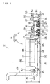
- Fig. 2 is a left side view of a measuring unit of the plate thickness measuring apparatus for the bottom plate of the cylindrical tank
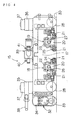
- Fig. 3 is a front view of a front measuring cart of the plate thickness measuring apparatus for the bottom plate of the cylindrical tank
- Fig. 4 is a right side view of a front measuring cart of the plate thickness measuring apparatus for the bottom plate of the cylindrical tank
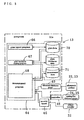
- Fig. 5 is a block diagram of a data processing system of a plate thickness measuring apparatus for the bottom plate of the cylindrical tank according to an embodiment of the present invention
- Fig. 6 is a top view of a plate whose thickness is to be measured
- Fig. 6 is a top view of a plate whose thickness is to be measured
- FIG. 7 is a top view showing a plate dividing state of the bottom plate of the cylindrical tank measured by the plate thickness measuring apparatus for the bottom plate of the cylindrical tank
- Fig. 8 is an explanatory diagram showing a plate thickness state of the bottom plate of the cylindrical tank measured by the plate thickness measuring apparatus for the bottom plate of the cylindrical tank.
- a plate thickness measuring apparatus 10 of a bottom plate of a cylindrical tank has a measuring unit 12 having a measuring cart 11, an operation and display unit 13 which processes measurement data from the measuring unit 12, and a water supply unit 14 which supplies water, which is an example of a coupling medium, to the measuring cart 11.
- a measuring unit 12 having a measuring cart 11
- an operation and display unit 13 which processes measurement data from the measuring unit 12
- a water supply unit 14 which supplies water, which is an example of a coupling medium, to the measuring cart 11.
- the operation and display unit 13 and the water supply unit 14 are not shown in Figs. 2 to 4 .
- the measuring unit 12 is equipped with the measuring cart 11 having a front cart 15 and a back cart 16 that are arranged and connected back and forth.
- Plural auxiliary carts 18 and 19 are provided respectively in the front side and back side of an opening 17 provided in a center of the lower part of the front cart 15.
- Each of the auxiliary carts 18 and 19 has a frame 20 and free wheels 21 attached in the front, back, right, and left thereof, and in a center section of each of the auxiliary carts 18 and 19, as shown in Fig. 4 , reflection type ultrasonic probes 22 and 23 are arranged.
- coating film thickness gauges 24 and 25 are provided in the back of each auxiliary cart 18, and the front of each auxiliary cart 19, respectively.
- Respective auxiliary carts 18 and 19 are attached to the front cart 15 through gimbal mechanisms 26 and 27 each of which is an example of a universal joint mechanism, respectively, and auxiliary carts 18 and 19 move with the free wheels 21 of the auxiliary carts 18 and 19 always in contact with a tank bottom surface 30 regardless of shaking of the front cart 15 in a vertical direction. That is, generally, the tank bottom surface 30 does not have a perfect flat surface, but has the "undulation", and further, since there are welded portions of joints and corroded portions in the bottom plate 31 locally, there are unevenness on the tank bottom surface 30.
- Respective auxiliary carts 18 and 19 move with following such unevenness of the tank bottom surface 30, and the ultrasonic probes 22 and 23 attached to these can move on the tank bottom surface 30 with always having a fixed gap G (refer to Fig. 3 ).
- reference numeral 28 denotes the front, back, right, and left wheels of the front cart 15.
- the auxiliary carts 18, arranged in the front of the opening 17, and the auxiliary carts 19, arranged in the rear of the opening 17, are arranged in the width direction of the measuring cart 11 at the same intervals respectively, the auxiliary carts 19 in the back row are arranged with shifting by a half pitch (in Fig. 3 , X/2) to the auxiliary carts 18 in the front row on their attachment positions.
- the reason why the auxiliary carts 18 in the front row and the auxiliary carts 19 in the back row are arranged in a staggered (zigzag) pattern in such a way is as follows.
- the ultrasonic probes 22 and 23 have certain width in flaw detection regions, since each is attached to the auxiliary cart 18 or 19, owing to the presence of the frame 20 and free wheels 21, an approach distance L (refer to Fig. 3 ) between the ultrasonic probes 22 and 23 adjacent to each other in a row is inevitably limited. For this reason, for example, in the case of using only the ultrasonic probes 22 in the front row (namely, one row), which are arranged in the horizontal single line, in the auxiliary carts 18, belt-like incapable measurement regions arise in interzonal portions with the adjacent ultrasonic probes 22.
- the auxiliary carts 19 are arranged in the central positions between respective auxiliary carts 18 in the moving direction of the front cart 15 so that the ultrasonic probes 23 in the other row can measure the unmeasurable regions of the ultrasonic probes 22 in the one row.
- the width of the unmeasurable region of the ultrasonic probes in one row is wide, namely, an unmeasurable region has the width of a half or more of a attachment pitch of each ultrasonic probe, since all regions cannot be measured even by a group of the ultrasonic probes arranged in two rows, in this case, the measurement of all the regions in the width direction of the measuring cart 11 becomes possible by providing a step-like group of the ultrasonic probes in three or more rows.
- the reflection type ultrasonic probes 22 and 23 used in this embodiment are, for example, split type ultrasonic probes (namely, double crystal probes) each having a transmitting element and a receiving element, which transmit and receive ultrasonic waves through wedges made of acrylic resins, polystyrene resins, or the like. It becomes possible to receive the reflected waves from the lower surface (back face side) of the bottom plate 31 without being influenced by the reflected waves of the ultrasonic waves from the upper surface (namely, the tank bottom surface 30) of the bottom plate 31 of the cylindrical tank near to transmitted pulses. Hence, it becomes possible to accurately measure the distance to a local reduced thickness portion generated in the bottom plate 31.
- Eddy current type sensors are used for coating film thickness gauges 24 and 25 provided in the auxiliary carts 18 and 19 respectively. If a coating film is on the surface of the tank bottom surface 30, the plate thickness measured by the ultrasonic probes 22 and 23 becomes the thickness including the total thickness of the coating thickness and steel plate thickness. Then, the actual thickness of the coating film is measured by the coating film thickness gauges 24 and 25 that are comprised of the eddy current type sensors, and a more accurate value is obtained by subtracting it from the distance measurements of the ultrasonic probes 22 and 23.
- a rotary encoder 32 is provided in the front of the front cart 15, which detects the rotation speed of the wheels 33 attached to the input shaft of the rotary encoder 32, and the traveling distance of this measuring cart 11 can be electrically measured.
- a frame 34 to which the rotary encoder 32 is attached is attached to the front cart 15 in a vertically movable or freely movable state, and a wheel 33 of the rotary encoder 32 always rotates in contact with the tank bottom surface 30.
- a horizontal guide wheel 37 is provided in a state of projecting parts thereof in the right and left sides through supporting tables 35 and 36.
- this horizontal guide wheel 37 contacts to the inside of the tank side plate, and hence the horizontal guide wheel 37 can smoothly move. Furthermore, the projection length of the horizontal guide wheel 37 can be extended up to 275 mm.
- an eyebolt 38 is provided, and hence it is possible to pull this measuring cart 11 with a rope or the like, one end of which is fixed to the eyebolt 38.
- a water distribution unit 39 is provided in an upper part of the front cart 15, water is supplied to a water spray unit provided in a lower end portion of each of the ultrasonic probes 22 and 23 through water feed holes provided in the front cart 15 via a flexible hose, not shown, which is connected to hose couplers (nipples) 40 and 41, which are arranged therebefore and thereafter, and gaps between the ultrasonic probes 22 and 23, and the tank bottom surface 30 are filled with water.
- hose couplers (nipples) 40 and 41 which are arranged therebefore and thereafter, and gaps between the ultrasonic probes 22 and 23, and the tank bottom surface 30 are filled with water.
- the back cart 16 connected with this front cart 15 has a cart frame 44 and four wheels 45 provided in the front, rear, right, and left, a housing 47 with a lid 46 is provided on this, and a controller 48 of the eddy current sensors constituting the coating film thickness gauges 24 and 25 is arranged in this housing 47.
- the thickness of the coating film applied on the surface of the tank bottom plate 31 is measured, and is outputted to an operation and display unit 13.
- the principle of an eddy current sensor is that the thickness of the coating film is detected by passing an alternating current in a detection coil, detecting that the impedance of the detection coil becomes small if the distance from the upper surface of the bottom plate 31 thereunder becomes large, and comparing this with the reference measured beforehand.
- an indicator of the controller 48 on the lid 46 of the housing 47.
- a removable operation handle 49 having the predetermined height (about 60 to 90 cm) is provided, so that an operator can move this measuring cart 11 to back and forth directions with this handle 49.
- the whole height of this measuring cart 11 can be made low, the measuring cart 11 can go under the piping arranged above the tank bottom surface 30, and can test the tank bottom plate 31. Therefore, it is possible to set the height H of the measuring cart 11 to be, for example, about 200 mm when the handle 49 is removed. Furthermore, to make it lower, it is also possible to set it to be about 100 mm by separating the front cart 15 from the back cart 16.
- a cable 51 comprised of bundling signal lines of respective ultrasonic probes 22 and 23, a signal line and a power line for the connection to the controller 48, a signal line of the rotary encoder 32, and control lines of a measurement start and end switch 50 is provided in a back portion of this back cart 16.
- This cable 51 is fixed to the back cart 16 by a cable stop 52 in the base portion thereof.
- the signal of the switch 50 is sent to the operation and display unit 13, and the plate thickness measurement of the tank bottom plate 31 is started and ended.
- the water supply unit 14 shown in Fig. 1 has a water tank 56 which can contain sufficient water, a pump 57 which pumps out water from the water tank 56, an electromagnetic valve 58 which turns on and off the water discharged from the pump 57, and the start and stop of operation of the pump 57, and ON/OFF of the electromagnetic valve 58 are performed on the basis of instructions of a computer 64 by the signal of the measurement start and end switch 50 provided in the measuring cart 11 being inputted into this computer 64 of the operation and display unit 13.
- a flexible hose 60 connects this water supply unit 14 with the water distribution unit 39 of the measuring cart 11, and if necessary, water from the water tank 56 is supplied between the ultrasonic probes 22 and 23 and the tank bottom surface 30.
- the operation and display unit 13 has a multi-channel type ultrasonic thickness gauge 63 that sends a predetermined signal to each of the ultrasonic probes 22 and 23 and receives an output signal from each of the ultrasonic probes 22 and 23, and the computer 64 to which this ultrasonic thickness gauge 63 is connected through an I/O plate not shown.
- This ultrasonic thickness gauge 63 is a multi-channel type, not only sends pulse signals to the plurality of ultrasonic probes 22 and 23 connected to this, but also measures plate thickness by receiving the pulse signals which the ultrasonic probes 22 and 23 detect, and converts them into a digital signal to send it to the computer 64.
- the coating film thickness gauges 24 and 25 are connected to the computer 64 through the controller 48, and the rotary encoder 32 is connected through a counter board 65, respectively.
- the computer 64 is a personal computer that is market-available and comprises a CPU, RAM, ROM, an auxiliary storage device, and I/O devices (for example, an A/D converter), calculates the actual plate thickness of the bottom plate 31 by processing signals sent from the rotary encoder 32, each of the ultrasonic probes 22 and 23, and each of the coating film thickness gauges 24 and 25 by the program which is described below and is set beforehand, and outputs the plate thickness with a position thereof to an attached output device (a display or a printer).
- an attached output device a display or a printer
- a plate layout program 66, a plate thickness display program 67, and a measurement program 68, which perform actual processing of the operation and display unit 13, are stored in memory such as a hard disk. Hereafter, these will be described in detail.
- the above-described plate layout program 66 creates a plate layout plan of the tank bottom plate 31 by inputting basic data, required for the creation of a tank plate cutting diagram, such as the number of the annular plates arranged around the tank bottom plate 31, the size of a plate which is a unit of the bottom plate 31 (refer to Fig. 7 ). It becomes possible to calculate the positional information of a plate by making this procedure (namely, a program) stored in a file, and to display only one plate on a CRT etc. independently.
- the tank plate layout plan created is saved as plot data 70 in a file.
- the positional information in a plate is added to the measured plate thickness data according to the length, measured by the rotary encoder, in the measurement direction by inputting the distance and the measurement direction of the plate (unit plate), which is measured, from an origin by making an arbitrary corner (or a specific position) of the bottom plate 31 be the origin.
- the data is saved by one point/channel at every fixed distance in the measurement direction, i.e., one data per one subsection. When much data exists in one subsection, a representative value (for example, a minimum plate thickness value) is saved as the data of the subsection.
- a plate, which is a measuring object, and a corner to be used as an origin are selected by using the plot data 70 created by the plate layout program 66.
- the plate thickness display program 67 creates a plate thickness distribution map for every plate and a whole plate thickness distribution map into which these are combined. Although these will be described below, the creation of the plate thickness distribution map per plate will be first described.
- Color-coded display according to the concerned position-plate thickness is performed every plate by using the plot data 70 and the measurement data 71.
- the following processing is performed so that a proper representative value of the measurement data 71 may be displayed on one pixel of a CRT (an example of a display) to display it. That is, as shown in Fig. 6 , for example, one plate 72 is divided into a lattice a side of which is made to be an interval (a fixed interval in the measurement direction) in which the measurement data 71 was acquired, and this one grid is made to be a cell 73. Next, a position and plate thickness are calculated from the measurement data 71, and the plate thickness data is set to the corresponding cell 73.
- Predetermined operation is performed when plate thickness data has been already set to the cell 73 where to be set, and the plate thickness data of the cell 73 is updated.
- the file generated is saved as per-plate plate thickness data A in a file.
- pixel size is calculated so that the whole plate may be displayed on the CRT.
- this pixel size is made to become an integral multiple of the area of the cell 73.
- This number of cells gathered is made to be a block 74 (in addition, the block 74 and a pixel have the relation of 1 to 1).
- a specific example is as follows.
- a representative value of the block 74 is calculated by performing predetermined operation for the cells 73 every block 74 obtained by the above method (for example, a minimum value is acquired), and color-coded display according to the plate thickness is performed to the representative value of this block 74. According to the above procedure, the proper color-coded distribution by the representative value can be displayed.
- the color-coded display according to the plate thickness is performed for the whole tank bottom plate 31 by using the per-plate plate thickness data A created with the above-described method.
- the following processing is performed so that the proper representative value of measurement data may be displayed in one pixel of the CRT to display it.
- the whole tank bottom plate 31 is divided into grids each side of which is the integral multiple (for example, 5 times) of an interval (a fixed interval in the measurement direction) in which measurement data is acquired.
- This one grid is called a cell H.
- plate thickness data is set to the concerned cell H from the per-plate plate thickness data A.
- Predetermined operation for example, acquiring a minimum value
- a file generated is called whole plate thickness data B.
- pixel size is calculated so that the whole tank bottom plate may be displayed on the CRT (it is made to become the integral multiple of the cell H).
- This number of cells H gathered is called a block D.
- the block D and a pixel have the relation of 1 to 1, and a specific example is shown below.
- the diameter of the tank bottom plate is 48000 mm, and a side of the cell is 25 mm
- 48000/480 100 (mm/pixel), which is rounded up
- 100/25 4 (cells/pixel), which is rounded up, and from the above, 4 x 4 cells are equivalent to one pixel.
- a representative value of the block D is calculated by performing predetermined operation (for example, acquiring a minimum value) for the cells H every block D obtained by the above method, and color-coded display according to the plate thickness is performed to the representative value of this block D. By these procedures, the proper color-coded distribution according to the representative value can be displayed.
- the plate thickness measured by the ultrasonic probes 22 and 23 is performed by measuring time until a ultrasonic pulse emitted from a transmitting element propagates in order of a coating film, a steel plate, steel plate bottom reflection, the steel plate, and the coating film, and reaches a receiving element, the plate thickness measured by the ultrasonic probes 22 and 23 are thickness containing the total thickness of the coating film thickness and steel plate thickness.
- the thickness measured by the coating film thickness gauges 24 and 25 is only coating film thickness.
- steel plate thickness i.e., the thickness of the actual tank bottom plate 31 is obtained by subtracting the coating film thickness, measured by the coating film thickness gauges 24 and 25, from the plate thickness obtained by the ultrasonic probes 22 and 23, respectively without removing the coating of the tank bottom plate 31.
- the ultrasonic probes 22 and 23 and the coating film thickness gauges 24 and 25 which are provided in six sets of auxiliary carts 18 and 19 (one set is hidden in Fig. 3 ), arranged in the width direction, respectively are attached to the measuring cart 11 under the certain positional relation in a plan view, and hence if what positional relation a certain position in the measuring cart 11 has with the tank bottom plate 31 is known, it is possible to know the positions of the tank bottom plate 31 that positions where the ultrasonic probes 22 and 23 and the coating film thickness gauges 24 and 25 in the auxiliary carts 18 and 19 perform measurement correspond to.
- the rotary encoder 32 which measures traveling distance, to the measuring cart 11, and grasping the traveling distance from a specific position of the tank bottom plate 31, it is possible to specify in real time the positions of the tank bottom plate 31 that positions where the ultrasonic probes 22 and 23 and the coating film thickness gauges 24 and 25 that are moving perform measurement correspond to, and also to measure the coating film thickness and the plate thickness of the specific position simultaneously.
- the relation between a position and steel plate thickness is displayed on a screen, it is possible to grasp a state of plate thickness reduction by the corrosion of the steel plate over the whole tank bottom plate 31.
- a measuring operator measures by manually moving the measuring cart 11 along a path, determined beforehand, on the tank bottom plate 31.
- the traveling speed of the measuring cart 11 is determined in consideration of the processing speed of measurement data, and measurement is usually performed at 500 to 1000 mm/second of traveling speed.
- the measuring cart 11 is made to be a handcart, it is also possible to make the measuring cart 11 be a mobile cart by providing a sensor if necessary, or determining a course beforehand.
- the measuring cart 11 Under structure such as a base heater in a tank which has restrictions in entrance height, by removing the handle 49 provided in the back cart 16, the measuring cart 11 can enter, and it becomes possible to measure the tank bottom plate 31.
- height H is, for example, 200 mm, but it is possible to make the height of the front cart 15 be the height of about 100 mm. For this reason, it becomes possible to measure a gap of up to about 100 mm by performing measurement only by the front cart 15 through separating or offsetting the front cart 15 from the measuring cart 11.
- those that have the effective beam width of 25 mm, and the capacity of being able to detect a flat bottom hole with the diameter of 2 mm which exists in the range of 5 to 35 mm in the measurement direction under a quiescent state are used as the ultrasonic probes 22 and 23
- eddy current type sensors which can measure the thickness range of 0 to 2 mm are as the coating film thickness gauges 24 and 25, and what can perform forward and backward distance measurement in the length measuring precision of 0.1% is as the rotary encoder 32.
- the measurement accuracy of plate thickness at the time of combining the ultrasonic probes 22 and 23 with the eddy current type sensors becomes ⁇ 0.1 mm.
- Measurement data is recorded in the computer 64 (refer to Fig. 5 ) as a representative value, for example, in a 5-mm moving interval by finding a minimum value out of all the data read until the moving length becomes 5 mm.
- a pulse repetition frequency of the ultrasonic thickness gauge 63 is set to be 500 Hz to 2 kHz, and a range measured at the time of the transmission and reception of ultrasonic pulses from the ultrasonic probes 22 and 23 is made to be a range of 25 mm x 3 mm (the value 25 mm is effective beam width that is orthogonal to the moving direction of the ultrasonic probes 22 and 23, and the value 3 mm is effective beam width in the moving direction) . Therefore, even if a measuring cart 11 is moved at the rate of 500 to 1000 mm/sec, an incapable flaw detection range in the moving direction does not arise.
- a plate with which measurement is started is selected from the bottom plate cutting diagram.
- the origin of a measurement starting position is selected from corners of a plate.
- the measurement starting position is inputted in the distance from the origin selected at the third step.
- the measurement direction is selected from up, down, left, and right directions.
- a straight line travel or a circular travel is selected.
- the reference point of the measuring cart 11 is aligned with the measurement starting position inputted at the fourth step, and the measurement start switch 50 is pushed. Then, measurement is performed by pushing the measuring cart 11 in the measurement direction selected at the fifth step.
- the measurement end switch 50 is pushed.
- the measuring cart 11 is moved to a next measurement starting position, and the fourth to eighth steps are repeated. Herewith, the measurement of the plate to be measured is completed.
- the color-coded display of the plate to be measured with corresponding to the plate thickness is performed by using the plate thickness display program 67.
- the color-coded display of the whole tank bottom plate with corresponding to the plate thickness is performed by using the plate thickness display program 67.
- the plate thickness measuring apparatus 10 for the bottom plate of a cylindrical tank according to an embodiment of the present invention is applied to the plate thickness measurement of the bottom plate 31 of the cylindrical tank whose inside diameter is 15 m will be further described.
- the contents of the measurement are divided into initial condition setup, measurement condition setup, a measuring method, and measured result display.
- a tank inside diameter, the number of annular plates, and the size of a basic bottom plate are inputted into the computer 64 of the operation and display unit 13.
- the computer 64 draws an annular plate, and creates bottom plate cutting diagrams with dividing the whole bottom plate vertically or horizontally, and further dividing each of the divided regions.
- the divided regions are automatically numbered.
- Fig. 7 shows the bottom plate cutting diagram created in the case that the plate thickness measurement is performed for the bottom plate 31 of a cylindrical tank with an inside diameter of 15 m.
- the number of the plate (refer to Fig. 7 ), which is measured, is selected from the bottom plate cutting diagram, and the origin, measurement starting point, and measurement direction at the time of measurement are determined about the plate having the selected number.
- the measured results of the plate thickness of the bottom plate (steel plate) 31 can be displayed in color-coding according to the grade of plate thickness in real time, and a state of plate thickness reduction can be shown on a screen.
- the measured results of steel plate thickness can be displayed into the bottom plate cutting diagram in color-coding according to the grade of plate thickness, and the color-coded plate thickness distribution map, a state of plate thickness cross sections in the vertical and horizontal directions at an arbitrary position, or the like can be displayed on a screen by selecting a plate with an arbitrary number.
- These contents displayed on a screen can be outputted by a color printer that is an example of an output unit.
- Fig. 8 The distribution situation of positions with a bottom plate thickness of less than 8 mm against the design bottom plate thickness of 10 mm is shown in Fig. 8 as an example of a state of plate thickness reduction obtained in the plate thickness measurement of the bottom plate 31 of a cylindrical tank with an inside diameter of 15 m.
- Table 1 the relation of the bottom plate thickness and area that is obtained over the whole tank bottom plate 31 is shown in Table 1.
- a plate thickness measuring apparatus for the bottom plate of a cylindrical tank according to the present invention, it is made to travel a measuring cart, in which reflection type ultrasonic probes which measure the thickness of a tank bottom plate, coating film thickness gauges which measure coating film thickness on the surface of the bottom plate, and a rotary encoder which measures traveling distance are attached, on the tank bottom plate, to measure the thickness of the actual bottom plate at a specific position of a tank bottom surface, and to display the relation between the position and the thickness in real time on a screen, and hence it becomes possible to accurately, simply, and quickly measure and evaluate a state of plate thickness reduction by the corrosion of a local steel plate over the whole tank bottom plate without removing the coating of the tank bottom plate. Since it becomes possible to perform measurement by setting the traveling speed of a measuring cart to be 500 to 1000 mm/second, it becomes possible to perform high-speed plate thickness measurement.
- auxiliary carts are arranged in a plurality of rows in the traveling direction of a measuring cart, and furthermore, in a staggered or step-like pattern, it is possible to perform a wide range of plate thickness measurement simultaneously, and to attain easy and rapid measurement.
- a double crystal probe of a transmitting element and a receiving element is composed of a reflection type ultrasonic probe, and an eddy current type sensor is composed of a coating film thickness gauge, it is possible to accurately measure and evaluate a state of plate thickness reduction without removing the coating of a tank bottom plate.
- a plate thickness measuring apparatus for the bottom plate of a cylindrical tank since the height of the whole measuring cart is made to be the height of being able to measure the thickness of a tank bottom plate with passing under the piping provided above the tank bottom plate, a large area of the tank bottom plate becomes an area which can be measured.
Landscapes
- Physics & Mathematics (AREA)
- General Physics & Mathematics (AREA)
- Analytical Chemistry (AREA)
- Health & Medical Sciences (AREA)
- Life Sciences & Earth Sciences (AREA)
- Chemical & Material Sciences (AREA)
- Biochemistry (AREA)
- General Health & Medical Sciences (AREA)
- Immunology (AREA)
- Pathology (AREA)
- Acoustics & Sound (AREA)
- Length Measuring Devices Characterised By Use Of Acoustic Means (AREA)
- Length Measuring Devices With Unspecified Measuring Means (AREA)
- Measurement Of Length, Angles, Or The Like Using Electric Or Magnetic Means (AREA)
Abstract
Description
- The present invention relates to a plate thickness measuring apparatus for a bottom plate of a cylindrical tank that measures a state of plate thickness reduction of a bottom plate of a cylindrical tank such as a fuel tank, and can evaluate this.
-
JP-A-11 019 890 - with the position as a center by using ultrasonic waves, and hence the state of the plate thickness reduction of the tank bottom near the problem position is grasped.
- However, the following problems that should be solved exist in the conventional plate thickness measurement of the bottom plate of a cylindrical tank.
- (1) In the plate thickness measurement of the tank bottom plate using ultrasonic waves, since acoustic velocities in a coating film portion and a steel plate portion differ greatly, if the measurement is performed from an upper surface of the coating film by using a general ultrasonic thickness gauge, a very large measurement error arises in the determination of the thickness of an actual bottom plate, i.e., steel plate thickness. Although a multi-echo type ultrasonic thickness gauge is developed as a counter-measure for this, if there is backside corrosion, it is difficult to correctly determine the state of the steel plate thickness reduction by the corrosion of the tank bottom plate since a multi-echo may not be obtained.
- (2) Therefore, on the occasion of measurement of steel plate thickness, a method is adopted in which plate thickness measurement is performed for only the steel plate portion after removing a coating film portion and recoat is performed after the measurement, however, there are a problem that an idle period of a tank becomes long on the occasion of the measurement and an economical problem that costs of coating film removal and recoat arise in addition to measurement cost.
- (3) Furthermore, there is a problem that, if a remarkable plate thickness reduction of the steel plate is not detected by the measurement at fixed points which are specified by providing intervals, remarkable plate thickness reduction is ignored even if it actually exists in a portion except the fixed points, it is impossible to detect a state of the plate thickness reduction of the steel plate by local corrosion, and hence it is not possible to grasp the state of the plate thickness reduction of the steel plate covering the whole tank bottom plate.
- (4) In addition, there is a problem that plate thickness measurement of the tank bottom plate cannot be performed simply and quickly since measurement is performed again at new fixed points, which are given by performing subdivision with a fixed point as a center, if remarkable plate thickness reduction is detected in the fixed point.
- The present invention is achieved in view of such situation, and aims to provide a plate thickness measuring apparatus for the bottom plate of a cylindrical tank which can grasp a state of plate thickness reduction of a steel plate covering the whole tank bottom plate without removing the coating of the tank bottom plate.
- The above-mentioned object can be attained by an apparatus according to the
independent claim 1. - Preferred embodiments are subject of the
dependent claims 2 to 5. -
Fig. 1 is a block diagram of each instrument of a plate thickness measuring apparatus for a bottom plate of a cylindrical tank according to an embodiment of the present invention,Fig. 2 is a left side view of a measuring unit of the plate thickness measuring apparatus for the bottom plate of the cylindrical tank,Fig. 3 is a front view of a front measuring cart of the plate thickness measuring apparatus for the bottom plate of the cylindrical tank,Fig. 4 is a right side view of a front measuring cart of the plate thickness measuring apparatus for the bottom plate of the cylindrical tank,Fig. 5 is a block diagram of a data processing system of a plate thickness measuring apparatus for the bottom plate of the cylindrical tank according to an embodiment of the present invention,Fig. 6 is a top view of a plate whose thickness is to be measured,Fig. 7 is a top view showing a plate dividing state of the bottom plate of the cylindrical tank measured by the plate thickness measuring apparatus for the bottom plate of the cylindrical tank, andFig. 8 is an explanatory diagram showing a plate thickness state of the bottom plate of the cylindrical tank measured by the plate thickness measuring apparatus for the bottom plate of the cylindrical tank. - As shown in
Figs. 1 to 4 , a platethickness measuring apparatus 10 of a bottom plate of a cylindrical tank according to an embodiment of the present invention has ameasuring unit 12 having ameasuring cart 11, an operation anddisplay unit 13 which processes measurement data from themeasuring unit 12, and a water supply unit 14 which supplies water, which is an example of a coupling medium, to themeasuring cart 11. Hereafter, these will be described in detail. In addition, the operation anddisplay unit 13 and the water supply unit 14 are not shown inFigs. 2 to 4 . - As shown in
Figs. 1 to 3 , themeasuring unit 12 is equipped with themeasuring cart 11 having afront cart 15 and aback cart 16 that are arranged and connected back and forth. Pluralauxiliary carts opening 17 provided in a center of the lower part of thefront cart 15. Each of theauxiliary carts frame 20 andfree wheels 21 attached in the front, back, right, and left thereof, and in a center section of each of theauxiliary carts Fig. 4 , reflection typeultrasonic probes film thickness gauges auxiliary cart 18, and the front of eachauxiliary cart 19, respectively. - Respective
auxiliary carts front cart 15 throughgimbal mechanisms auxiliary carts free wheels 21 of theauxiliary carts tank bottom surface 30 regardless of shaking of thefront cart 15 in a vertical direction. That is, generally, thetank bottom surface 30 does not have a perfect flat surface, but has the "undulation", and further, since there are welded portions of joints and corroded portions in thebottom plate 31 locally, there are unevenness on thetank bottom surface 30. Respectiveauxiliary carts tank bottom surface 30, and theultrasonic probes tank bottom surface 30 with always having a fixed gap G (refer toFig. 3 ). In addition,reference numeral 28 denotes the front, back, right, and left wheels of thefront cart 15. - Although the
auxiliary carts 18, arranged in the front of theopening 17, and theauxiliary carts 19, arranged in the rear of theopening 17, are arranged in the width direction of themeasuring cart 11 at the same intervals respectively, theauxiliary carts 19 in the back row are arranged with shifting by a half pitch (inFig. 3 , X/2) to theauxiliary carts 18 in the front row on their attachment positions. The reason why theauxiliary carts 18 in the front row and theauxiliary carts 19 in the back row are arranged in a staggered (zigzag) pattern in such a way is as follows. - Although the
ultrasonic probes auxiliary cart frame 20 andfree wheels 21, an approach distance L (refer toFig. 3 ) between theultrasonic probes ultrasonic probes 22 in the front row (namely, one row), which are arranged in the horizontal single line, in theauxiliary carts 18, belt-like incapable measurement regions arise in interzonal portions with the adjacentultrasonic probes 22. In order to be able to measure such belt-like incapable measurement regions, produced by the travel of theauxiliary carts 18, by using theultrasonic probes 23 of theauxiliary carts 19 in the back row (namely, another row), theauxiliary carts 19 are arranged in the central positions between respectiveauxiliary carts 18 in the moving direction of thefront cart 15 so that theultrasonic probes 23 in the other row can measure the unmeasurable regions of theultrasonic probes 22 in the one row. - In addition, although an ultrasonic pulse of each of the
ultrasonic probes auxiliary carts ultrasonic probes auxiliary carts - Here, if the width of the unmeasurable region of the ultrasonic probes in one row is wide, namely, an unmeasurable region has the width of a half or more of a attachment pitch of each ultrasonic probe, since all regions cannot be measured even by a group of the ultrasonic probes arranged in two rows, in this case, the measurement of all the regions in the width direction of the
measuring cart 11 becomes possible by providing a step-like group of the ultrasonic probes in three or more rows. - The reflection type
ultrasonic probes bottom plate 31 without being influenced by the reflected waves of the ultrasonic waves from the upper surface (namely, the tank bottom surface 30) of thebottom plate 31 of the cylindrical tank near to transmitted pulses. Hence, it becomes possible to accurately measure the distance to a local reduced thickness portion generated in thebottom plate 31. - Eddy current type sensors are used for coating
film thickness gauges auxiliary carts tank bottom surface 30, the plate thickness measured by theultrasonic probes film thickness gauges ultrasonic probes - A
rotary encoder 32 is provided in the front of thefront cart 15, which detects the rotation speed of thewheels 33 attached to the input shaft of therotary encoder 32, and the traveling distance of thismeasuring cart 11 can be electrically measured. Aframe 34 to which therotary encoder 32 is attached is attached to thefront cart 15 in a vertically movable or freely movable state, and awheel 33 of therotary encoder 32 always rotates in contact with thetank bottom surface 30. - Then, as shown in
Figs. 2 and4 , at the front and back of the upper portion of thefront cart 15, ahorizontal guide wheel 37 is provided in a state of projecting parts thereof in the right and left sides through supporting tables 35 and 36. When thefront cart 15 is located near the inside of the tank side plate, thishorizontal guide wheel 37 contacts to the inside of the tank side plate, and hence thehorizontal guide wheel 37 can smoothly move. Furthermore, the projection length of thehorizontal guide wheel 37 can be extended up to 275 mm. In front of the supporting table 35, aneyebolt 38 is provided, and hence it is possible to pull this measuringcart 11 with a rope or the like, one end of which is fixed to theeyebolt 38. - Furthermore, as shown in
Figs. 2 to 4 , awater distribution unit 39 is provided in an upper part of thefront cart 15, water is supplied to a water spray unit provided in a lower end portion of each of theultrasonic probes front cart 15 via a flexible hose, not shown, which is connected to hose couplers (nipples) 40 and 41, which are arranged therebefore and thereafter, and gaps between theultrasonic probes tank bottom surface 30 are filled with water. Owing to this, while ultrasonic waves being certainly propagated from theultrasonic probes bottom plate 31, the reflected waves from thebottom plate 31 can be also propagated to theultrasonic probes - The
back cart 16 connected with thisfront cart 15 has acart frame 44 and fourwheels 45 provided in the front, rear, right, and left, ahousing 47 with alid 46 is provided on this, and acontroller 48 of the eddy current sensors constituting the coatingfilm thickness gauges housing 47. With thiscontroller 48, the thickness of the coating film applied on the surface of thetank bottom plate 31 is measured, and is outputted to an operation anddisplay unit 13. In addition, although being commonly known, the principle of an eddy current sensor is that the thickness of the coating film is detected by passing an alternating current in a detection coil, detecting that the impedance of the detection coil becomes small if the distance from the upper surface of thebottom plate 31 thereunder becomes large, and comparing this with the reference measured beforehand. In addition, it is also possible to arrange an indicator of thecontroller 48 on thelid 46 of thehousing 47. - In a far backend of the
back cart 16, aremovable operation handle 49 having the predetermined height (about 60 to 90 cm) is provided, so that an operator can move this measuringcart 11 to back and forth directions with thishandle 49. In addition, by removing thehandle 49, the whole height of thismeasuring cart 11 can be made low, themeasuring cart 11 can go under the piping arranged above thetank bottom surface 30, and can test thetank bottom plate 31. Therefore, it is possible to set the height H of themeasuring cart 11 to be, for example, about 200 mm when thehandle 49 is removed. Furthermore, to make it lower, it is also possible to set it to be about 100 mm by separating thefront cart 15 from theback cart 16. - A
cable 51 comprised of bundling signal lines of respectiveultrasonic probes controller 48, a signal line of therotary encoder 32, and control lines of a measurement start and end switch 50 is provided in a back portion of thisback cart 16. Thiscable 51 is fixed to theback cart 16 by acable stop 52 in the base portion thereof. In addition, the signal of the switch 50 is sent to the operation anddisplay unit 13, and the plate thickness measurement of thetank bottom plate 31 is started and ended. - In addition, the water supply unit 14 shown in
Fig. 1 has a water tank 56 which can contain sufficient water, apump 57 which pumps out water from the water tank 56, an electromagnetic valve 58 which turns on and off the water discharged from thepump 57, and the start and stop of operation of thepump 57, and ON/OFF of the electromagnetic valve 58 are performed on the basis of instructions of acomputer 64 by the signal of the measurement start and end switch 50 provided in the measuringcart 11 being inputted into thiscomputer 64 of the operation anddisplay unit 13. A flexible hose 60 connects this water supply unit 14 with thewater distribution unit 39 of the measuringcart 11, and if necessary, water from the water tank 56 is supplied between theultrasonic probes tank bottom surface 30. - As shown in
Figs. 1 and5 , the operation anddisplay unit 13 has a multi-channel typeultrasonic thickness gauge 63 that sends a predetermined signal to each of theultrasonic probes ultrasonic probes computer 64 to which thisultrasonic thickness gauge 63 is connected through an I/O plate not shown. Thisultrasonic thickness gauge 63 is a multi-channel type, not only sends pulse signals to the plurality ofultrasonic probes ultrasonic probes computer 64. In addition, the coating film thickness gauges 24 and 25 are connected to thecomputer 64 through thecontroller 48, and therotary encoder 32 is connected through acounter board 65, respectively. In addition, thecomputer 64 is a personal computer that is market-available and comprises a CPU, RAM, ROM, an auxiliary storage device, and I/O devices (for example, an A/D converter), calculates the actual plate thickness of thebottom plate 31 by processing signals sent from therotary encoder 32, each of theultrasonic probes - The system outline of this
computer 64 is shown inFig. 5 . Aplate layout program 66, a platethickness display program 67, and ameasurement program 68, which perform actual processing of the operation anddisplay unit 13, are stored in memory such as a hard disk. Hereafter, these will be described in detail. - The above-described
plate layout program 66 creates a plate layout plan of thetank bottom plate 31 by inputting basic data, required for the creation of a tank plate cutting diagram, such as the number of the annular plates arranged around thetank bottom plate 31, the size of a plate which is a unit of the bottom plate 31 (refer toFig. 7 ). It becomes possible to calculate the positional information of a plate by making this procedure (namely, a program) stored in a file, and to display only one plate on a CRT etc. independently. Here, the tank plate layout plan created is saved asplot data 70 in a file. - In addition, in the
measurement program 68, the positional information in a plate is added to the measured plate thickness data according to the length, measured by the rotary encoder, in the measurement direction by inputting the distance and the measurement direction of the plate (unit plate), which is measured, from an origin by making an arbitrary corner (or a specific position) of thebottom plate 31 be the origin. The data is saved by one point/channel at every fixed distance in the measurement direction, i.e., one data per one subsection. When much data exists in one subsection, a representative value (for example, a minimum plate thickness value) is saved as the data of the subsection. A plate, which is a measuring object, and a corner to be used as an origin are selected by using theplot data 70 created by theplate layout program 66. In consideration of making the measuringcart 11 travel along the periphery of the tank, it is made possible to perform plate thickness measurement even in the case of a circular travel of the measuringcart 11 in addition to a straight travel. In addition, a file with the created information on the measuring points, plate thickness, and film thickness is saved asmeasurement data 71. - Next, the plate
thickness display program 67 will be described. The platethickness display program 67 creates a plate thickness distribution map for every plate and a whole plate thickness distribution map into which these are combined. Although these will be described below, the creation of the plate thickness distribution map per plate will be first described. - Color-coded display according to the concerned position-plate thickness is performed every plate by using the
plot data 70 and themeasurement data 71. The following processing is performed so that a proper representative value of themeasurement data 71 may be displayed on one pixel of a CRT (an example of a display) to display it. That is, as shown inFig. 6 , for example, oneplate 72 is divided into a lattice a side of which is made to be an interval (a fixed interval in the measurement direction) in which themeasurement data 71 was acquired, and this one grid is made to be acell 73. Next, a position and plate thickness are calculated from themeasurement data 71, and the plate thickness data is set to thecorresponding cell 73. Predetermined operation (for example, acquiring a minimum value) is performed when plate thickness data has been already set to thecell 73 where to be set, and the plate thickness data of thecell 73 is updated. Here, the file generated is saved as per-plate plate thickness data A in a file. Then, pixel size is calculated so that the whole plate may be displayed on the CRT. In addition, this pixel size is made to become an integral multiple of the area of thecell 73. This number of cells gathered is made to be a block 74 (in addition, theblock 74 and a pixel have the relation of 1 to 1). A specific example is as follows. - When a number of CRT pixels is 640 x 480, a width of the plate is 7200 mm, and a cell size is 5 mm,
7200/640 = 11.25 ≦12 (mm/pixel), which is rounded up,
12/5 = 2.25 ≦3 (cells/pixel), which is rounded up,
and from the above, 3 x 3 cells are equivalent to one pixel. - Then, a representative value of the
block 74 is calculated by performing predetermined operation for thecells 73 everyblock 74 obtained by the above method (for example, a minimum value is acquired), and color-coded display according to the plate thickness is performed to the representative value of thisblock 74. According to the above procedure, the proper color-coded distribution by the representative value can be displayed. - Next, the creation of a whole plate thickness distribution map will be described.
- The color-coded display according to the plate thickness is performed for the whole
tank bottom plate 31 by using the per-plate plate thickness data A created with the above-described method. The following processing is performed so that the proper representative value of measurement data may be displayed in one pixel of the CRT to display it. - First, the whole
tank bottom plate 31 is divided into grids each side of which is the integral multiple (for example, 5 times) of an interval (a fixed interval in the measurement direction) in which measurement data is acquired. This one grid is called a cell H. Then, plate thickness data is set to the concerned cell H from the per-plate plate thickness data A. Predetermined operation (for example, acquiring a minimum value) is performed when plate thickness data has been already set to the cell H to be set, and the plate thickness data of the cell H is updated. Here, a file generated is called whole plate thickness data B. - Next, pixel size is calculated so that the whole tank bottom plate may be displayed on the CRT (it is made to become the integral multiple of the cell H). This number of cells H gathered is called a block D. The block D and a pixel have the relation of 1 to 1, and a specific example is shown below.
- When the number of CRT pixels is 640 x 480, the diameter of the tank bottom plate is 48000 mm, and a side of the cell is 25 mm,
48000/480 = 100 (mm/pixel), which is rounded up,
100/25 = 4 (cells/pixel), which is rounded up,
and from the above, 4 x 4 cells are equivalent to one pixel. - A representative value of the block D is calculated by performing predetermined operation (for example, acquiring a minimum value) for the cells H every block D obtained by the above method, and color-coded display according to the plate thickness is performed to the representative value of this block D. By these procedures, the proper color-coded distribution according to the representative value can be displayed.
- Next, a plate thickness measuring method for the
bottom plate 31 of a cylindrical tank where the platethickness measuring apparatus 10 for the bottom plate of a cylindrical tank according to an embodiment of the present invention is applied will be described. - Since the plate thickness measurement by the
ultrasonic probes ultrasonic probes tank bottom plate 31 is obtained by subtracting the coating film thickness, measured by the coating film thickness gauges 24 and 25, from the plate thickness obtained by theultrasonic probes tank bottom plate 31. - In addition, the
ultrasonic probes auxiliary carts 18 and 19 (one set is hidden inFig. 3 ), arranged in the width direction, respectively are attached to the measuringcart 11 under the certain positional relation in a plan view, and hence if what positional relation a certain position in the measuringcart 11 has with thetank bottom plate 31 is known, it is possible to know the positions of thetank bottom plate 31 that positions where theultrasonic probes auxiliary carts rotary encoder 32, which measures traveling distance, to the measuringcart 11, and grasping the traveling distance from a specific position of thetank bottom plate 31, it is possible to specify in real time the positions of thetank bottom plate 31 that positions where theultrasonic probes tank bottom plate 31 by combining the plate thickness by theultrasonic probes rotary encoder 32. In addition, if the relation between a position and steel plate thickness is displayed on a screen, it is possible to grasp a state of plate thickness reduction by the corrosion of the steel plate over the wholetank bottom plate 31. - In the actual plate thickness measurement of the
tank bottom plate 31, a measuring operator measures by manually moving the measuringcart 11 along a path, determined beforehand, on thetank bottom plate 31. The traveling speed of the measuringcart 11 is determined in consideration of the processing speed of measurement data, and measurement is usually performed at 500 to 1000 mm/second of traveling speed. In addition, in this embodiment, although the measuringcart 11 is made to be a handcart, it is also possible to make the measuringcart 11 be a mobile cart by providing a sensor if necessary, or determining a course beforehand. - Under structure such as a base heater in a tank which has restrictions in entrance height, by removing the
handle 49 provided in theback cart 16, the measuringcart 11 can enter, and it becomes possible to measure thetank bottom plate 31. - In addition, since the
controller 48 of the coating film thickness gauges 24 and 25, and the display of measurements are incorporated in theback cart 16, height H is, for example, 200 mm, but it is possible to make the height of thefront cart 15 be the height of about 100 mm. For this reason, it becomes possible to measure a gap of up to about 100 mm by performing measurement only by thefront cart 15 through separating or offsetting thefront cart 15 from the measuringcart 11. At the time of measuring only by thefront cart 15, it is possible to adopt a method of attaching a rope to theeyebolt 38 provided in the front end of thefront cart 15 and pulling thefront cart 15 as an example of a moving method of thefront cart 15. - In the face of the
tank bottom plate 31, an unmeasurable region arises inevitably near an obstruction such as a wear plate with the obstruction as a center owing to access limitation of the measuringcart 11. In this case also, it becomes possible to reduce the unmeasurable region by separating or offsetting thefront cart 15. - In this embodiment, those that have the effective beam width of 25 mm, and the capacity of being able to detect a flat bottom hole with the diameter of 2 mm which exists in the range of 5 to 35 mm in the measurement direction under a quiescent state are used as the
ultrasonic probes rotary encoder 32. In this case, the measurement accuracy of plate thickness at the time of combining theultrasonic probes - Measurement data is recorded in the computer 64 (refer to
Fig. 5 ) as a representative value, for example, in a 5-mm moving interval by finding a minimum value out of all the data read until the moving length becomes 5 mm. - A pulse repetition frequency of the
ultrasonic thickness gauge 63 is set to be 500 Hz to 2 kHz, and a range measured at the time of the transmission and reception of ultrasonic pulses from theultrasonic probes value 25 mm is effective beam width that is orthogonal to the moving direction of theultrasonic probes value 3 mm is effective beam width in the moving direction) . Therefore, even if a measuringcart 11 is moved at the rate of 500 to 1000 mm/sec, an incapable flaw detection range in the moving direction does not arise. - Therefore, in the plate thickness measuring apparatus for the bottom plate of a cylindrical tank according to an embodiment of the present invention, measurement will be performed at the following steps as described above. First step (creation of tank bottom plate cutting diagram by plate layout program 66)
- Based on the drawing of a tank, a bottom plate cutting diagram is created before the measurement.
- A plate with which measurement is started is selected from the bottom plate cutting diagram.
- The origin of a measurement starting position is selected from corners of a plate.
- The measurement starting position is inputted in the distance from the origin selected at the third step.
- The measurement direction is selected from up, down, left, and right directions.
- A straight line travel or a circular travel is selected.
- The reference point of the measuring
cart 11 is aligned with the measurement starting position inputted at the fourth step, and the measurement start switch 50 is pushed. Then, measurement is performed by pushing the measuringcart 11 in the measurement direction selected at the fifth step. - When a measuring cart holder comes to the end point of the plate in the measurement direction, the measurement end switch 50 is pushed.
- The measuring
cart 11 is moved to a next measurement starting position, and the fourth to eighth steps are repeated. Herewith, the measurement of the plate to be measured is completed. - The color-coded display of the plate to be measured with corresponding to the plate thickness is performed by using the plate
thickness display program 67. - The measurement of all the plates to be measured is completed by repeating the second to tenth steps. Twelfth step (creation of whole plate thickness distribution map)
- The color-coded display of the whole tank bottom plate with corresponding to the plate thickness is performed by using the plate
thickness display program 67. - Then, a case that the plate
thickness measuring apparatus 10 for the bottom plate of a cylindrical tank according to an embodiment of the present invention is applied to the plate thickness measurement of thebottom plate 31 of the cylindrical tank whose inside diameter is 15 m will be further described. The contents of the measurement are divided into initial condition setup, measurement condition setup, a measuring method, and measured result display. - A tank inside diameter, the number of annular plates, and the size of a basic bottom plate are inputted into the
computer 64 of the operation anddisplay unit 13. - Based on an input data, the
computer 64 draws an annular plate, and creates bottom plate cutting diagrams with dividing the whole bottom plate vertically or horizontally, and further dividing each of the divided regions. The divided regions are automatically numbered.Fig. 7 shows the bottom plate cutting diagram created in the case that the plate thickness measurement is performed for thebottom plate 31 of a cylindrical tank with an inside diameter of 15 m. In addition, since such processing is described above in detail, it will be omitted here. - The number of the plate (refer to
Fig. 7 ), which is measured, is selected from the bottom plate cutting diagram, and the origin, measurement starting point, and measurement direction at the time of measurement are determined about the plate having the selected number. -
- a) The position of a measurement starting point is inputted in the displacement from the origin.
- b) The reference point of the measuring
cart 11 is aligned with the measurement starting position, and the measurement start switch 50 is pressed. - c) The measuring
cart 11 is moved in the measurement direction at the speed of 500 to 1000 mm/second. The measuringcart 11 is moved so that the traveling direction of the measuringcart 11 may coincide with the optical axis of a laser beam of a laser oscillator installed beforehand so that the measurement direction might be shown. - d) A measurement end switch 50 is pressed when the measuring
cart 11 arrives at the end point of the plate. - e) From the end point position, the measuring
cart 11 is moved to a next measurement starting position. In addition, in the case of movement in the direction that is orthogonal (90°) to the measurement direction of the measuringcart 11, a cross-directionally moving cart is used. A cross-directionally moving cart is a dedicated cart for moving the measuringcart 11 in the direction orthogonal to the measurement direction of the measuringcart 11 with the measuringcart 11 being placed thereon. - f) When the measuring
cart 11 moves on the whole surface in the plate with the selected number by repeating the above steps a) to e), the measurement of the plate with the selected number is completed. - g) The number of the plate, which is measured next, is selected from the bottom plate cutting diagram, and steps a) to f) are performed.
- h) When the plate thickness measurement of all the plates in the bottom plate cutting diagram is completed, it means that the plate thickness measurement of the
tank bottom plate 31 is completed. - During the measurement, the measured results of the plate thickness of the bottom plate (steel plate) 31 can be displayed in color-coding according to the grade of plate thickness in real time, and a state of plate thickness reduction can be shown on a screen. After the measurement, the measured results of steel plate thickness can be displayed into the bottom plate cutting diagram in color-coding according to the grade of plate thickness, and the color-coded plate thickness distribution map, a state of plate thickness cross sections in the vertical and horizontal directions at an arbitrary position, or the like can be displayed on a screen by selecting a plate with an arbitrary number. These contents displayed on a screen can be outputted by a color printer that is an example of an output unit. In addition, it is possible to display and output an average of plate thickness, a minimum value of plate thickness, and the distribution of areas of portions, whose plate thickness is more than a fixed plate thickness, according to the number of a plate. The distribution situation of positions with a bottom plate thickness of less than 8 mm against the design bottom plate thickness of 10 mm is shown in
Fig. 8 as an example of a state of plate thickness reduction obtained in the plate thickness measurement of thebottom plate 31 of a cylindrical tank with an inside diameter of 15 m. In addition, the relation of the bottom plate thickness and area that is obtained over the wholetank bottom plate 31 is shown in Table 1. In addition, since such processing is described above in detail, it will be omitted here.[Table 1] Class of steel plate thickness (mm) Area (cm2) Rate (%) Note t ≥ 10 845678 44.5 10 > t ≥ 9.0 1031905 54.3 9.0 > t ≥ 8.0 2260 0.1 8.0 > t ≥ 7.0 25 0.0 t < 7.0 0 0.0 Not measured 21080 1.1 Unmeasurable area Total 1900948 100.0 Design steel plate thickness: 10.0 mm
Average steel plate thickness: 9.83 mm
Minimum steel plate thickness: 7.10 mm - Moreover, although specific numbers are used for description in the above-described embodiment, the present invention is not limited to these numbers.
- In a plate thickness measuring apparatus for the bottom plate of a cylindrical tank according to the present invention, it is made to travel a measuring cart, in which reflection type ultrasonic probes which measure the thickness of a tank bottom plate, coating film thickness gauges which measure coating film thickness on the surface of the bottom plate, and a rotary encoder which measures traveling distance are attached, on the tank bottom plate, to measure the thickness of the actual bottom plate at a specific position of a tank bottom surface, and to display the relation between the position and the thickness in real time on a screen, and hence it becomes possible to accurately, simply, and quickly measure and evaluate a state of plate thickness reduction by the corrosion of a local steel plate over the whole tank bottom plate without removing the coating of the tank bottom plate. Since it becomes possible to perform measurement by setting the traveling speed of a measuring cart to be 500 to 1000 mm/second, it becomes possible to perform high-speed plate thickness measurement.
- In a plate thickness measuring apparatus for the bottom plate of a cylindrical tank according to the present invention, if auxiliary carts are arranged in a plurality of rows in the traveling direction of a measuring cart, and furthermore, in a staggered or step-like pattern, it is possible to perform a wide range of plate thickness measurement simultaneously, and to attain easy and rapid measurement.
- In addition, in a plate thickness measuring apparatus for the bottom plate of a cylindrical tank according to the present invention, since a double crystal probe of a transmitting element and a receiving element is composed of a reflection type ultrasonic probe, and an eddy current type sensor is composed of a coating film thickness gauge, it is possible to accurately measure and evaluate a state of plate thickness reduction without removing the coating of a tank bottom plate.
- Then, in a plate thickness measuring apparatus for the bottom plate of a cylindrical tank according to the present invention, since the height of the whole measuring cart is made to be the height of being able to measure the thickness of a tank bottom plate with passing under the piping provided above the tank bottom plate, a large area of the tank bottom plate becomes an area which can be measured.
Claims (5)
- A plate thickness measuring apparatus for a bottom plate of a cylindrical tank for measuring a thickness of the tank bottom plate by ultrasonic and evaluating a state of plate thickness reduction of the tank bottom plate, the tank bottom-Plate having a coating film on a surface thereof, the apparatus characterized by comprising:a measuring cart (11) for traveling on the tank bottom plate to be measured;plural auxiliary carts (18, 19) which are arranged in a width direction of the measuring cart and moreover attached to the measuring cart through universal joint mechanisms (26, 27);reflection type ultrasonic probes (22, 23) for measuring a thickness of the tank bottom plate, and coating film thickness gauges (24, 25) for measuring a thickness of a coating film on a surface of the tank bottom plate, both of which are attached in each of the auxiliary carts (18, 19);a rotary encoder (32) which is attached to the measuring cart and measures a traveling distance of the measuring cart; andan operation and display unit (13) for measuring an actual thickness of the tank bottom plate using a multi-channel type ultrasonic thickness gauge, the actual thickness being obtained by subtracting the thickness of the coating film at a specific position of the tank bottom plate based on the outputs of the respective ultrasonic probes and outputs of the respective coating film thickness gauges, furthermore, specifying the measurement positions of the ultrasonic probes (22, 23) and coating film thickness gauges (24, 25) based on an output of the rotary encoder (32) and displaying the relation between the position of the bottom plate and the thickness thereof on a screen by color-coding according to the measured thickness of the tank bottom plate,wherein the measuring cart (11) comprises a front cart (15) and a back cart (16) which are arranged front and back and connected with each other, and the auxiliary carts (18, 19) are provided in an opening (17) formed in a center of the lower part of the front cart (15), and arranged in plural rows in the traveling direction of the measuring cart (11) and in a staggered or step-like pattern in a plan view, whereby the adjacent ultrasonic probes are prevented from interfering with each other and measurement of a whole region of the width direction of the measuring cart (11) is possible by the ultrasonic probes (22, 23) attached to the auxiliary carts,and moreover, each of the coating film thickness gauges (24, 25) is comprised of an eddy current type sensor and is provided separately from the ultrasonic probes.
- The plate thickness measuring apparatus for a bottom plate of a cylindrical tank according to claim 1,
characterized in that horizontal guide wheels (37) are provided respectively in a front and a back of an upper portion of the front cart (15) through supporting tables (35, 36). - The plate thickness measuring apparatus for a bottom plate of a cylindrical tank according to claim 2,
characterized in that the ultrasonic probes (22, 23) are provided in center sections of the respective auxiliary carts (18, 19) and the coating film thickness gauges (24, 25) are provided in front portions or back portions of the respective auxiliary carts (18, 19). - The plate thickness measuring apparatus for a bottom plate of a cylindrical tank according to claim 1,
characterized in that an operation handle (49) provided in the measuring cart is detachable, whereby it is possible to measure the thickness of the tank bottom plate by the measuring cart (11) passing under piping provided above the tank bottom plate. - The plate thickness measuring apparatus for a bottom plate of a cylindrical tank according to claim 1,
characterized in that a pulse repetition frequency applied to the respective ultrasonic probes (22, 23) is 500 Hz to 2 kHz.
Applications Claiming Priority (3)
| Application Number | Priority Date | Filing Date | Title |
|---|---|---|---|
| JP22165699A JP3670525B2 (en) | 1999-08-04 | 1999-08-04 | Thickness measuring device for cylindrical tank bottom plate |
| JP22165699 | 1999-08-04 | ||
| PCT/JP2000/005123 WO2001011317A1 (en) | 1999-08-04 | 2000-07-31 | Thickness measuring device for cylindrical tank bottom plate |
Publications (3)
| Publication Number | Publication Date |
|---|---|
| EP1209444A1 EP1209444A1 (en) | 2002-05-29 |
| EP1209444A4 EP1209444A4 (en) | 2002-11-06 |
| EP1209444B1 true EP1209444B1 (en) | 2010-12-15 |
Family
ID=16770205
Family Applications (1)
| Application Number | Title | Priority Date | Filing Date |
|---|---|---|---|
| EP00948331A Expired - Lifetime EP1209444B1 (en) | 1999-08-04 | 2000-07-31 | Thickness measuring device for cylindrical tank bottom plate |
Country Status (8)
| Country | Link |
|---|---|
| US (1) | US6691576B1 (en) |
| EP (1) | EP1209444B1 (en) |
| JP (1) | JP3670525B2 (en) |
| KR (1) | KR100614141B1 (en) |
| AU (1) | AU6183500A (en) |
| DE (1) | DE60045381D1 (en) |
| TW (1) | TW438964B (en) |
| WO (1) | WO2001011317A1 (en) |
Cited By (1)
| Publication number | Priority date | Publication date | Assignee | Title |
|---|---|---|---|---|
| US11698335B1 (en) | 2022-02-28 | 2023-07-11 | Saudi Arabian Oil Company | Storage tank apparatus for online inspection |
Families Citing this family (13)
| Publication number | Priority date | Publication date | Assignee | Title |
|---|---|---|---|---|
| JP4740718B2 (en) * | 2005-11-08 | 2011-08-03 | 新日本非破壊検査株式会社 | Ultrasonic thickness measuring device |
| US7617730B2 (en) * | 2006-06-28 | 2009-11-17 | The Boeing Company | Ultrasonic inspection and repair mode selection |
| US7757558B2 (en) * | 2007-03-19 | 2010-07-20 | The Boeing Company | Method and apparatus for inspecting a workpiece with angularly offset ultrasonic signals |
| US7712369B2 (en) * | 2007-11-27 | 2010-05-11 | The Boeing Company | Array-based system and method for inspecting a workpiece with backscattered ultrasonic signals |
| JP5051849B2 (en) * | 2008-03-13 | 2012-10-17 | 旭化成エンジニアリング株式会社 | Method for estimating maximum corrosion rate of tank bottom plate |
| JP5730183B2 (en) * | 2011-12-14 | 2015-06-03 | 三菱重工業株式会社 | Ultrasonic flaw detector |
| US9631919B2 (en) | 2013-06-12 | 2017-04-25 | Applied Materials, Inc. | Non-contact sheet resistance measurement of barrier and/or seed layers prior to electroplating |
| US20180232874A1 (en) * | 2017-02-10 | 2018-08-16 | Ecosubsea As | Inspection vehicle |
| CN107907079A (en) * | 2017-11-16 | 2018-04-13 | 哈尔滨工程大学 | A kind of ultrasound thin oil film calibration testboard |
| US11415260B2 (en) * | 2019-11-06 | 2022-08-16 | Saudi Arabian Oil Company | Robotic inspection device for tank and pipe inspections |
| US11526168B2 (en) | 2019-11-14 | 2022-12-13 | Saudi Arabian Oil Company | Robotic inspection of in-service tanks through lower wall |
| CN111089877A (en) * | 2019-12-31 | 2020-05-01 | 苏州先机动力科技有限公司 | Nondestructive testing method and equipment for thermal barrier coating |
| WO2024203245A1 (en) | 2023-03-24 | 2024-10-03 | Jfeスチール株式会社 | Map generation method, map generation device, and surface inspection device |
Family Cites Families (13)
| Publication number | Priority date | Publication date | Assignee | Title |
|---|---|---|---|---|
| JPS6415959U (en) * | 1987-07-10 | 1989-01-26 | ||
| JPS6415959A (en) | 1987-07-10 | 1989-01-19 | Matsushita Electronics Corp | Positioning device of semiconductor element |
| US4857766A (en) | 1987-10-30 | 1989-08-15 | International Business Machine Corporation | BiMos input circuit |
| JPH0687052B2 (en) | 1989-01-24 | 1994-11-02 | 新日本製鐵株式会社 | Ultrasonic testing equipment for steel plate |
| US5062298A (en) * | 1989-12-05 | 1991-11-05 | E. I. Du Pont De Nemours And Company | Non-contact wet or dry film thickness measuring device using eddy current and ultrasonic sensors |
| US5201225A (en) | 1990-09-24 | 1993-04-13 | Toyo Kanetsu K.K. | Instrument for measuring thickness of coated plate and method thereof |
| JP2812819B2 (en) | 1991-07-19 | 1998-10-22 | 中部電力株式会社 | Ultrasonic plate thickness measuring device |
| JPH06347250A (en) | 1993-06-04 | 1994-12-20 | Asahi Eng Co Ltd | Plate thickness measuring device |
| JPH0734308A (en) | 1993-07-14 | 1995-02-03 | Shuji Kurimoto | Welding method and welding tool |
| JPH07128084A (en) | 1993-09-08 | 1995-05-19 | Yokogawa Electric Corp | Measurement data storage device |
| US5440929A (en) | 1993-11-22 | 1995-08-15 | Industrial Technology Research Institute | Ultrasonic device for measuring thickness of a tank bottom flat plate |
| JP2953301B2 (en) | 1994-04-28 | 1999-09-27 | 日本鋼管株式会社 | Ultrasonic flaw detection method and device |
| JP2814376B1 (en) * | 1997-06-30 | 1998-10-22 | 東電工業株式会社 | Robot for measuring tank bottom plate thickness |
-
1999
- 1999-08-04 JP JP22165699A patent/JP3670525B2/en not_active Expired - Lifetime
-
2000
- 2000-07-31 KR KR1020027000597A patent/KR100614141B1/en not_active Expired - Fee Related
- 2000-07-31 WO PCT/JP2000/005123 patent/WO2001011317A1/en not_active Ceased
- 2000-07-31 DE DE60045381T patent/DE60045381D1/en not_active Expired - Lifetime
- 2000-07-31 AU AU61835/00A patent/AU6183500A/en not_active Abandoned
- 2000-07-31 EP EP00948331A patent/EP1209444B1/en not_active Expired - Lifetime
- 2000-07-31 US US10/048,450 patent/US6691576B1/en not_active Expired - Lifetime
- 2000-08-03 TW TW089115607A patent/TW438964B/en not_active IP Right Cessation
Cited By (1)
| Publication number | Priority date | Publication date | Assignee | Title |
|---|---|---|---|---|
| US11698335B1 (en) | 2022-02-28 | 2023-07-11 | Saudi Arabian Oil Company | Storage tank apparatus for online inspection |
Also Published As
| Publication number | Publication date |
|---|---|
| US6691576B1 (en) | 2004-02-17 |
| KR100614141B1 (en) | 2006-08-25 |
| DE60045381D1 (en) | 2011-01-27 |
| EP1209444A1 (en) | 2002-05-29 |
| KR20020035102A (en) | 2002-05-09 |
| AU6183500A (en) | 2001-03-05 |
| TW438964B (en) | 2001-06-07 |
| JP2001050736A (en) | 2001-02-23 |
| EP1209444A4 (en) | 2002-11-06 |
| WO2001011317A1 (en) | 2001-02-15 |
| JP3670525B2 (en) | 2005-07-13 |
Similar Documents
| Publication | Publication Date | Title |
|---|---|---|
| US6691576B1 (en) | Thickness measuring device for cylindrical tank bottom plate | |
| JP4004503B2 (en) | Thickness measuring device for container steel plate | |
| CN101454663A (en) | Ultrasonic Flaw Detection Devices and Ultrasonic Flaw Detection Procedures | |
| US4270389A (en) | Method and apparatus for the automatic ultrasonic flaw detection | |
| US5440929A (en) | Ultrasonic device for measuring thickness of a tank bottom flat plate | |
| GB1559469A (en) | Method and apparatus for automatic ultrasonic flaw detection | |
| US5426978A (en) | Non-destructive axle flaw detecting apparatus | |
| AU759780B2 (en) | Method and device for displaying signal generated by measurement probe | |
| JP3529744B2 (en) | Steel plate thickness measuring device | |
| JP4004536B2 (en) | Thickness measuring device for container steel plate | |
| JP2002228431A (en) | Apparatus and method for measuring thickness of tank bottom plate | |
| JP3469877B2 (en) | Steel plate thickness measurement method | |
| JP4004537B2 (en) | Sheet thickness measurement method | |
| JP4004535B2 (en) | Thickness measuring device for container steel plate | |
| JP3748879B2 (en) | Apparatus and method for measuring thickness of cylindrical tank bottom plate | |
| JPH07333201A (en) | Ultrasonic flaw detection method for piping | |
| JP2000292142A (en) | Tank bottom plate diagnostic device | |
| JPS61133857A (en) | Method and apparatus for diagnosing corrosion of underground pipeline | |
| US5122991A (en) | Distance measuring apparatus and method | |
| JPS62133389A (en) | Method and device for inspecting size of fuel aggregate | |
| JPH063341A (en) | Self-propelled flaw detector | |
| JP2001153850A (en) | Image display method and device for ultrasonic flaw detection | |
| JP2601718B2 (en) | Automatic measurement equipment for barge loading soil volume | |
| JPH08219749A (en) | Method and device for measuring gap value at bottom of socket | |
| JPS6221014A (en) | Ultrasonic flaw detection tester |
Legal Events
| Date | Code | Title | Description |
|---|---|---|---|
| PUAI | Public reference made under article 153(3) epc to a published international application that has entered the european phase |
Free format text: ORIGINAL CODE: 0009012 |
|
| 17P | Request for examination filed |
Effective date: 20020301 |
|
| AK | Designated contracting states |
Kind code of ref document: A1 Designated state(s): AT BE CH CY DE DK ES FI FR GB GR IE IT LI LU MC NL PT SE |
|
| AX | Request for extension of the european patent |
Free format text: AL;LT;LV;MK;RO;SI |
|
| RAP1 | Party data changed (applicant data changed or rights of an application transferred) |
Owner name: ASAHI ENGINEERING CO., LTD. |
|
| A4 | Supplementary search report drawn up and despatched |
Effective date: 20020920 |
|
| AK | Designated contracting states |
Kind code of ref document: A4 Designated state(s): AT BE CH CY DE DK ES FI FR GB GR IE IT LI LU MC NL PT SE |
|
| RBV | Designated contracting states (corrected) |
Designated state(s): DE FR GB |
|
| 17Q | First examination report despatched |
Effective date: 20071218 |
|
| GRAP | Despatch of communication of intention to grant a patent |
Free format text: ORIGINAL CODE: EPIDOSNIGR1 |
|
| RIC1 | Information provided on ipc code assigned before grant |
Ipc: G01B 7/06 20060101ALI20100526BHEP Ipc: G01B 17/02 20060101AFI20100526BHEP |
|
| GRAS | Grant fee paid |
Free format text: ORIGINAL CODE: EPIDOSNIGR3 |
|
| GRAA | (expected) grant |
Free format text: ORIGINAL CODE: 0009210 |
|
| RBV | Designated contracting states (corrected) |
Designated state(s): DE GB NL |
|
| RIN1 | Information on inventor provided before grant (corrected) |
Inventor name: NISHIMURA,YUJI Inventor name: KAJIKI, RYOTA Inventor name: KIYOTA, FUMINORI Inventor name: NOJIRI, KAZUHIROASAHI ENGINEERING CO., LTD. Inventor name: SATO, NOBUYOSHIASAHI ENGINEERING CO., LTD. Inventor name: FUKUNAGA, TATSUYAASAHI ENGINEERING CO., LTD. |
|
| AK | Designated contracting states |
Kind code of ref document: B1 Designated state(s): DE GB NL |
|
| REG | Reference to a national code |
Ref country code: GB Ref legal event code: FG4D |
|
| REF | Corresponds to: |
Ref document number: 60045381 Country of ref document: DE Date of ref document: 20110127 Kind code of ref document: P |
|
| REG | Reference to a national code |
Ref country code: NL Ref legal event code: T3 |
|
| PLBE | No opposition filed within time limit |
Free format text: ORIGINAL CODE: 0009261 |
|
| STAA | Information on the status of an ep patent application or granted ep patent |
Free format text: STATUS: NO OPPOSITION FILED WITHIN TIME LIMIT |
|
| 26N | No opposition filed |
Effective date: 20110916 |
|
| REG | Reference to a national code |
Ref country code: DE Ref legal event code: R097 Ref document number: 60045381 Country of ref document: DE Effective date: 20110916 |
|
| PGFP | Annual fee paid to national office [announced via postgrant information from national office to epo] |
Ref country code: GB Payment date: 20160727 Year of fee payment: 17 Ref country code: DE Payment date: 20160726 Year of fee payment: 17 |
|
| PGFP | Annual fee paid to national office [announced via postgrant information from national office to epo] |
Ref country code: NL Payment date: 20170614 Year of fee payment: 18 |
|
| REG | Reference to a national code |
Ref country code: DE Ref legal event code: R119 Ref document number: 60045381 Country of ref document: DE |
|
| GBPC | Gb: european patent ceased through non-payment of renewal fee |
Effective date: 20170731 |
|
| PG25 | Lapsed in a contracting state [announced via postgrant information from national office to epo] |
Ref country code: DE Free format text: LAPSE BECAUSE OF NON-PAYMENT OF DUE FEES Effective date: 20180201 Ref country code: GB Free format text: LAPSE BECAUSE OF NON-PAYMENT OF DUE FEES Effective date: 20170731 |
|
| REG | Reference to a national code |
Ref country code: NL Ref legal event code: MM Effective date: 20180801 |
|
| PG25 | Lapsed in a contracting state [announced via postgrant information from national office to epo] |
Ref country code: NL Free format text: LAPSE BECAUSE OF NON-PAYMENT OF DUE FEES Effective date: 20180801 |