EP1209409B1 - Outdoor lamp having an improved illumination output - Google Patents
Outdoor lamp having an improved illumination output Download PDFInfo
- Publication number
- EP1209409B1 EP1209409B1 EP00128273A EP00128273A EP1209409B1 EP 1209409 B1 EP1209409 B1 EP 1209409B1 EP 00128273 A EP00128273 A EP 00128273A EP 00128273 A EP00128273 A EP 00128273A EP 1209409 B1 EP1209409 B1 EP 1209409B1
- Authority
- EP
- European Patent Office
- Prior art keywords
- reflector
- light
- area
- areas
- designed
- Prior art date
- Legal status (The legal status is an assumption and is not a legal conclusion. Google has not performed a legal analysis and makes no representation as to the accuracy of the status listed.)
- Expired - Lifetime
Links
Images
Classifications
-
- F—MECHANICAL ENGINEERING; LIGHTING; HEATING; WEAPONS; BLASTING
- F21—LIGHTING
- F21V—FUNCTIONAL FEATURES OR DETAILS OF LIGHTING DEVICES OR SYSTEMS THEREOF; STRUCTURAL COMBINATIONS OF LIGHTING DEVICES WITH OTHER ARTICLES, NOT OTHERWISE PROVIDED FOR
- F21V7/00—Reflectors for light sources
- F21V7/04—Optical design
- F21V7/09—Optical design with a combination of different curvatures
-
- F—MECHANICAL ENGINEERING; LIGHTING; HEATING; WEAPONS; BLASTING
- F21—LIGHTING
- F21V—FUNCTIONAL FEATURES OR DETAILS OF LIGHTING DEVICES OR SYSTEMS THEREOF; STRUCTURAL COMBINATIONS OF LIGHTING DEVICES WITH OTHER ARTICLES, NOT OTHERWISE PROVIDED FOR
- F21V7/00—Reflectors for light sources
- F21V7/10—Construction
-
- F—MECHANICAL ENGINEERING; LIGHTING; HEATING; WEAPONS; BLASTING
- F21—LIGHTING
- F21W—INDEXING SCHEME ASSOCIATED WITH SUBCLASSES F21K, F21L, F21S and F21V, RELATING TO USES OR APPLICATIONS OF LIGHTING DEVICES OR SYSTEMS
- F21W2131/00—Use or application of lighting devices or systems not provided for in codes F21W2102/00-F21W2121/00
- F21W2131/10—Outdoor lighting
- F21W2131/101—Outdoor lighting of tunnels or the like, e.g. under bridges
-
- F—MECHANICAL ENGINEERING; LIGHTING; HEATING; WEAPONS; BLASTING
- F21—LIGHTING
- F21W—INDEXING SCHEME ASSOCIATED WITH SUBCLASSES F21K, F21L, F21S and F21V, RELATING TO USES OR APPLICATIONS OF LIGHTING DEVICES OR SYSTEMS
- F21W2131/00—Use or application of lighting devices or systems not provided for in codes F21W2102/00-F21W2121/00
- F21W2131/10—Outdoor lighting
- F21W2131/103—Outdoor lighting of streets or roads
Definitions
- the invention relates to an outdoor lamp according to the preamble of claim 1.
- a lamp is z. B. from the DE 198 34 195 A1 known.
- Outdoor luminaires with a reflector made up of facets have generally proven useful in street lighting and the like, especially since they provide a way of defining the areas to be illuminated more precisely and individually than with conventional techniques.
- dark stripes are observed on the surfaces to be illuminated and / or on walls which adjoin the surface to be illuminated.
- These stripes are particularly noticeable in road tunnels and on road surfaces with a high mirror factor. This streaking occurs in particular in the near field area, for example at a distance of 3 m to 6 m from the luminaire.
- Such near-field effects can not be determined by light intensity distribution measurements during production and construction and only appear as illuminance irregularities directly under the luminaire or on the walls.
- CA 2 247 233 A1 discloses a luminaire with a parabolic reflector and a Kocnpaktleuchtstoffrschreibe arranged therein.
- this document proposes to divide the reflector in the circumferential direction in segments of 90 °. The reflector surface of two segments is highly distorted, while the reflector surface of the other two segments is dotted to cause light scattering.
- EP 0 732 538 A2 relates to a luminous element with a faceted reflector.
- the reflector facets are alternately either smooth or provided with a light-diffusing structure.
- EP 0 790 115 A2 relates to a method for producing a reflector for a vehicle headlight.
- the reflector is manufactured by injection molding and has a surface quality, which allows a subsequent metallization without a further intermediate layer.
- this object is achieved by an outdoor lamp, in particular for illuminating a strip-shaped terrain or room section, z.
- a road or a tunnel As a road or a tunnel, according to claim 1.
- At least one first coherent one of a side wall of the reflector, Light at least partially scattering area and at least a second continuous, light directed reflecting area of the reflector are provided.
- the light at least partially scattering region of the reflector may reflect a part of the incident light directed and scatter a further portion of the light.
- a surface structure having portions having a smooth surface reflecting light is formed in the corresponding area, and irregularly shaped surface portions reflecting the light incident from a certain direction due to the irregularity in different directions.
- the irregularly shaped surface sections taken by themselves, can be quite reflective. However, these surface portions are so small as compared to the total area of the subject area, or possibly also compared to the directionally reflective portions of this area, that the proportion of light reflected from such an irregular structure in a particular direction is small compared to the whole reflected amount of light is.
- the substantially directionally reflective areas of the reflector are usually formed with a smooth surface. According to the invention, however, these areas can also scatter a small part of the reflected light, but this proportion is smaller, usually much smaller than the proportion that is reflected by the first area scattering.
- the first and second regions have at least those dimensions at which the light at least partially scattering surfaces appear uniform, e.g. uniformly matt or uniform (not necessarily regular) structured. These dimensions are greater than the distance at which the surface structure varies or shows irregularities. If the reflector has facets, the first and second regions are preferably each at least as large as one facet.
- the invention can provide that a region or that region of the reflector, which light at least partially reflected in the vicinity of the lamp, light is formed at least partially scattering.
- the near zone may be defined as a room area in which illuminated areas (e.g., road surfaces or tunnel walls) with a distance from the luminaire are smaller than a certain threshold, the threshold may be in a range of 3 m to 6 m.
- an area of the reflector which reflects light on a region of the illuminated terrain or room section, which is at a distance of 3 m to 6 m from the lamp, at least partially scattering light, z.
- At least one reflector region which reflects light up to an angle of 0 ° to 40 ° with respect to a perpendicular to the light exit surface of the reflector, may be at least partially light-scattering. While the range of angles given above encompasses those angles which result in most practical applications, depending on the lighting task to be solved, e.g. B. depending on how high the lamp is mounted above the ground, at which distance from the light illuminated surfaces, such as house or tunnel walls, this critical angle can be selected larger.
- the invention may also provide that at least one reflector region, which reflects light up to an angle of 0 ° to 40 °, relative to the vertical in space, light is formed at least partially scattering.
- the reflector is at least partially constructed of reflector strips of individual facets, which extend, starting from the light exit opening, in a direction perpendicular to this, wherein at least one contiguous group of facets, which facets of one or more strips .
- Light is at least partially scattering formed and / or at least one contiguous group of facets, which facets of one or more reflector strips, is formed substantially directionally reflective.
- two or more of the aforementioned groups may also be provided.
- facets which reflect in the vicinity of the lamp, light may be formed at least partially scattering.
- the reflector has a roof section and reflective side walls, wherein at least one region of the side walls adjoining the roof section is formed at least partially scattering light.
- the roof section may also be wholly or partially subdivided light-scattering also.
- the invention may also provide that a directly adjacent to the light exit opening portion of the reflector is designed to be reflective.
- the invention may also provide that the reflector and the lamp of the luminaire are designed and arranged such that the spatial region in which light is reflected by the reflector is substantially larger in a plane parallel to the light exit surface along a first axis than along one vertical second axis, wherein at least one reflector region which reflects light in a direction substantially parallel to the second axis, at least partially scattering light, z. B. is formed matte. It can be provided in particular that at least one reflector region which reflects light substantially in a direction perpendicular to the longitudinal axis of the illuminated terrain section, at least partially formed light scattering.
- the invention may quite well provide that at least one or more of one or more further reflector regions which reflect light into an angular range about said second axis in the aforesaid plane and about the direction perpendicular to the longitudinal direction of the illuminated terrain section are formed scattering.
- This angular range can z. B. in a range of ⁇ 10 ° to ⁇ 80 °. If the terrain section to be illuminated is narrow and surrounded by walls, for example in narrow tunnels, this angular range can be very large, for example in the case of narrow tunnels. 80 °, while when the area to be illuminated is wider, it will generally be smaller.
- the luminaire according to the invention can be inclined to the horizontal, so that the light exit surface is not parallel to the horizontal.
- the above-mentioned relations and dimensions, in particular the specified angular ranges, according to an embodiment of the invention with respect to the horizontal plane, instead of with respect to a plane parallel to the light exit surface, may be provided.
- Such a design of the reflector is advantageous if, in the direction in which this reflector region reflects, there is a wall on which a striped pattern of the reflector can emerge.
- the invention may provide that reflector regions which reflect light in two opposite directions, each substantially parallel to said second axis, are at least partially diffused.
- Such an embodiment is particularly advantageous if there are walls in the direction of the second axis on both sides of the lamp, as z. B. in road tunnels is the case.
- the light-scattering regions of the reflector are provided with a light that at least partially diffuses the light.
- Such a structure may be, for example, a sandblast structure, a hammer blow structure, or a leather grain structure.
- a leather grain structure can provide a structure of line-like elevations, in particular on a surface which is in itself smooth. which are irregular in terms of both their course and height. These elevations form narrow strips which run through the surface and whose width is relatively small in relation to the area in question, for. B. to the area of a facet.
- the surface of the increase can be quite self-reflective. However, since their width is very narrow, the proportion of reflected light is relatively small. Accordingly, since the course of this surface is irregular, small amounts of light are irregularly reflected in different directions, thereby resulting in a light-scattering effect.
- the invention can also provide that the surface of the corresponding area is a vault structure, as for example by a method according to DE 43 11 978 C1 . DE 44 01 974 A1 . DE 44 37 986 A1 . DE 195 12 533 A1 . DE 196 11 478 A1 . DE 196 34 244 A1 or DE 196 51 937 A1
- a structure does not necessarily have to be made by a method according to any of the above references, but has only the same properties as a structure produced by this method.
- the reflector is made of plastic, alternative methods of producing identical or similar structures may be used.
- the structure may also be designed in such a way that a part of the light incident on the corresponding area is reflected in a directed manner and a further part of the light incident on the area is scattered, whereby the proportion of the directed light can definitely predominate. Due to the light scattering share is achieved that the space area in the corresponding reflector area, z. B. one or more facets, reflected, not sharply defined, but rather has a smeared transition, d. H. an edge region in which the light intensity of the light reflected by the facet does not fall sharply, but drops off with a more or less extended edge.
- areas with different light at least partially scattering structures may be provided in the reflector.
- the light-scattering areas of the reflector are not absolutely necessary to provide the light-scattering areas of the reflector with a light-scattering structure. It can also be provided that these areas of the Reflectors are provided with a light at least partially scattering coating, paint or the like.
- the invention also provides a method of manufacturing a reflector for a luminaire as described above, wherein the reflector is formed by a molding tool characterized in that the molding tool is provided in areas corresponding to light at least partially diffusing areas of the reflector the negative of a light is at least partially scattering structure provided.
- the reflector is molded from plastic.
- the molding tool is polished in areas which correspond to reflectively directed areas of the reflector.
- the smooth areas of the mold lead accordingly to smooth surfaces of the reflector, while rough surfaces of the mold lead to a rough and thus light-scattering surface of the reflector.
- the mold is polished even in areas where a light-scattering structure is provided, so that the surfaces of the structure are locally smooth and thus specularly reflective. The light scattering effect results in these cases by the macroscopically irregular course of the surface.
- the invention may also provide that the inner wall of the reflector is provided with a reflective coating after the molding process.
- a part of the mold is provided with a structure which corresponds to the negative of a light at least partially scattering structure and another part of the mold is completely smooth, so that results in the molding process, a smooth surface of the reflector, results after coating with a reflective material automatically in the areas where a structure already exists, a light scattering effect, while in those areas where the mold completely was smooth and, accordingly, the reflector wall is smooth, resulting in a directionally reflective area.
- the invention may also provide that the reflector is conventionally formed from sheet metal that has been patterned prior to molding with a light-scattering structure. If the reflector made of Belch, a step shape between the individual reflector strips can be difficult to realize, so that it can also be provided that between two directly adjacent reflector strip in the direction perpendicular to the reflective surface remains a space not filled by material.
- the reflector pot is made of sheet metal, it may be useful to construct the reflector pot from several individual parts, for example, a first part, which contains the structured facets and a second part, which contains the non-structured facets.
- the invention is based on the surprising finding that the above-described streakiness can be generally solved without significant losses for the efficiency of the luminaire and for the luminous intensity distribution, that a part of the reflector light is at least partially scattering and formed another part of the reflector high gloss is.
- the high-gloss areas or facets which preferably lie in the region of the light exit opening or adjacent to it, ensure optimum and targeted light distribution on the section to be illuminated, e.g. a road surface, and thus for the optimum lighting quality, which manifests itself in the case of street lighting in a high luminance of the road, a high luminance uniformity of the road and in glare limitation of the lamp with the lowest possible number of lights and low energy consumption of the individual lights.
- the matt reflector areas ensure targeted light scattering and light insulation.
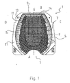
- Fig. 1 shows a schematic plan view of a reflector of a lamp according to the invention.
- Fig. 1 shows a generally designated 1 reflector for a street lamp according to the invention, the reflective inner surface has the shape of an oval, which at the two End faces is cut or cut.
- Fig. 1 shows the view of the light exit opening of this reflector.
- a lamp (not shown) is used, the supply line and socket are inserted through the recess 5 on the designated A front side of the reflector in this.
- the reflector 1 has a roof portion 7, which has a regular structure of pyramidal elevations, which are indicated in the drawing, and side walls 9 1 , 9 2 and 9 3 , which extend between the light exit opening and this roof section.
- the side walls 9 1 and 9 2 are constructed of reflector strips 11 which extend between the light exit opening and the roof portion 7 and are arranged adjacent to each other along the circumference of the reflector 1, so that the entire periphery of the reflector is formed by such reflector strips.
- the transition between the individual reflector strips 11 is not necessarily continuous, but can be step-shaped, corresponding to the different orientation of the facets in adjacent reflector strips. Even within the reflector strips, the transition between the individual facets, which are each individually oriented, need not necessarily be continuous. Successive facets of a strip may also be slightly offset from each other.
- the reflector strips themselves are in turn each constructed from a plurality of reflector facets 13 which are arranged successively in the direction from the light exit opening to the roof section 7.
- the sidewall 9 3 is formed by a single region of specularly reflective reflector facets 14 extending across the entire width of this sidewall.
- Each of these reflector facets 13 and 14 substantially reflects light from the lamp within a certain angular range.
- the entirety of the reflector facets determines the luminous intensity distribution curve of the luminaire or the illuminance or the luminance distribution on the terrain section to be illuminated.
- the illuminance or the luminance distribution can be built up from the individual reflections of the individual facets and thus be designed in a wide range.
- Reflector facets located near the light exit aperture tend to reflect into a far region of the luminaire or at relatively shallow angles to the light exit aperture, while facets which are closer to the roof portion 7 reflect into the near zone of the luminaire.
- the reflector facets on the two end faces A and B reflect in a direction transverse or oblique to the road direction
- the lamp shown is the roof section 7 with the pyramidal elevations matte or diffuse reflective formed.
- the in Fig. 1 hatched reflector facets formed light scattering.
- the non-hatched facets have a directionally reflective design. It can be seen that in a region 15 of facets which adjoins the light exit opening and extends over the entire circumference of the reflector, the facets are reflective. However, the width of this area varies. Near the face A, this area is narrow, while it is wider in the middle of the side faces C and D. In the area of the long sides C and D reflect the matte reflector facets on the floor in the vicinity of the lamp.
- the directionally or specularly reflective reflector facets reflect into the femoral region. It has been found that by the light scattering training of the corresponding reflector facets in the vicinity of the streakiness z. B. is lifted on the ground or adjacent tunnel walls. In contrast, a light-scattering design of the facets in the area near the light exit opening is not necessary because there the problem of banding does not occur and seeks in the remote area as directed radiation to illuminate areas at long distances from the lamp.
- the region of the light at least partially scattering facets extends closer to the light exit opening on the front side A than on the sides C and D, has two reasons.
- the emission range of the luminaire along the axis E is substantially smaller than along the axis F. Accordingly, more facets also reflect on the side A on the ground in the vicinity of the luminaire.
- Light is also imparted to these walls by such facets, which reflect light only at a relatively shallow angle to the light exit opening, which would normally be attributable to the remote emission area, if the light reflected by these facets were incident on the floor.
- the light already hits above the floor on a wall at a distance from the lamp, which may well be in the vicinity, ie at a distance of about 3 m to 6 m, so that form stripes on the walls. Therefore, in the region A, also those facets which only reflect light at a shallow angle to the light exit opening are light-scattering in order to avoid these fringe effects on walls.
- the luminaire according to the invention can, with regard to the reflector structure in particular as in the DE 198 34 195 A1 be described, reference is made to the reference and with respect to the formation of the reflector and the lamp in general by way of reference forms an integral part of this description. Referring to Figs. 2 and 3 of this reference, the area of directionally reflective facets around the light exit aperture in the reflector strip A would be relatively narrow, then increase in areas B, C, D, E and F and then in areas G and H again lose weight.
- the facets on the side 9 3 are all directed or mirror-inverted. Such a design is useful if there are no illuminated areas in the vicinity of the lamp on the side opposite the side B. However, if such surfaces are present in the vicinity of the front side B, as is the case for example in tunnels, and the side 9 3 may be formed similar to the region of the side A, such that, starting from the roof portion 7, a or a plurality of successive facets 14 light are formed at least partially scattering, where appropriate, the entire region of the side wall 9 3 may be formed light scattering.
- the reflector shown above was integrally formed, it may also be formed by a plurality of parts.
- the side wall 9 3 is designed as an insert, which, depending on the desired lighting task, can be exchanged for a light-scattering use.
- the reflector is arranged so that the specularly reflective wall 9 3 can be covered by an insert which is wholly or partially formed light scattering.
- the in Fig. 1 shown reflector is received in accordance with an embodiment of the invention in a lamp housing or forms such a lamp housing.
- the invention may also provide that two or more such reflectors are accommodated in a luminaire housing.
- Two or more reflectors, as in Fig. 1 can also be formed from one piece and connected to each other via the edge regions 17.
Landscapes
- Engineering & Computer Science (AREA)
- General Engineering & Computer Science (AREA)
- Non-Portable Lighting Devices Or Systems Thereof (AREA)
- Compositions Of Macromolecular Compounds (AREA)
- Organic Low-Molecular-Weight Compounds And Preparation Thereof (AREA)
- Optical Elements Other Than Lenses (AREA)
Abstract
Description
Die Erfindung betrifft eine Außenleuchte gemäß dem Oberbegriff des Anspruchs 1. Eine derartige Leuchte ist z. B. aus der
Außenleuchten mit einem Reflektor, der aus Facetten aufgebaut ist, haben sich allgemein bei Straßenbeleuchtungen und dergleichen bewährt, insbesondere da sie eine Möglichkeit geben, die auszuleuchtenden Bereiche präziser und individueller als mit konventionellen Techniken festzulegen. In der Praxis hat sich jedoch herausgestellt, daß auf den zu beleuchtenden Flächen und/oder auf Wänden, welche an die zu beleuchtenden Fläche angrenzen, z. B. Hausfassaden an einer Straße, dunkle Streifen zu beobachten sind. Diese Streifen sind besonders auffallend in Straßentunneln und auf Straßenbelägen mit einem hohen Spiegelfaktor. Diese Streifigkeit tritt insbesondere im Nahfeldbereich auf, etwa in einem Abstand von 3 m bis 6 m von der Leuchte. Derartige Nahfeldeffekte sind durch Lichtstärkeverteilungsmessungen bei der Herstellung und Konstruktion nicht feststellbar und stellen sich erst als Beleuchtungsstärkeungleichmäßigkeiten direkt unter der Leuchte bzw. auf den Wänden heraus.Outdoor luminaires with a reflector made up of facets have generally proven useful in street lighting and the like, especially since they provide a way of defining the areas to be illuminated more precisely and individually than with conventional techniques. In practice, however, it has been found that on the surfaces to be illuminated and / or on walls which adjoin the surface to be illuminated, z. As house facades on a street, dark stripes are observed. These stripes are particularly noticeable in road tunnels and on road surfaces with a high mirror factor. This streaking occurs in particular in the near field area, for example at a distance of 3 m to 6 m from the luminaire. Such near-field effects can not be determined by light intensity distribution measurements during production and construction and only appear as illuminance irregularities directly under the luminaire or on the walls.
Es ist eine Aufgabe der Erfindung, eine Leuchte der eingangs genannten Art zur Verfügung zu stellen, welche kostengünstig hergestellt werden kann und bei welcher Beleuchtungsstärkeungleichmäßigkeiten in bestimmten Bereichen reduziert sind.It is an object of the invention to provide a luminaire of the type mentioned, which can be produced inexpensively and in which illuminance irregularities are reduced in certain areas.
Erfindungsgemäß wird diese Aufgabe gelöst durch eine Außenleuchte, insbesondere zur Beleuchtung eines streifenförmigen Gelände- oder Raumabschnitts, z. B. einer Straße oder eines Tunnels, nach Anspruch 1.According to the invention this object is achieved by an outdoor lamp, in particular for illuminating a strip-shaped terrain or room section, z. As a road or a tunnel, according to
Es kann insbesondere vorgesehen sein, daß an einer Seitenwand des Reflektors zumindest ein erster zusammenhängender, Licht zumindest teilweise streuender Bereich und mindestens ein zweiter zusammenhängender, Licht gerichtet reflektierender Bereich des Reflektors vorgesehen sind.It may be provided, in particular, that at least one first coherent one of a side wall of the reflector, Light at least partially scattering area and at least a second continuous, light directed reflecting area of the reflector are provided.
Der Licht zumindest teilweise streuende Bereich des Reflektors kann einen Teil des einfallenden Lichts gerichtet reflektieren und einen weiteren Anteil des Lichts streuen. Beispielsweise kann vorgesehen sein, daß in dem entsprechenden Bereich eine Oberflächenstruktur ausgebildet ist, welche Abschnitte mit einer glatten Oberfläche aufweist, die Licht gerichtet reflektieren, und unregelmäßig ausgebildete Oberflächenabschnitte, welche das aus einer bestimmten Richtung einfallende Licht aufgrund der Unregelmäßigkeit in verschiedene Richtungen reflektieren. Die unregelmäßig ausgebildeten Oberflächenabschnitte können, für sich genommen, durchaus spiegelnd reflektierend sein. Diese Oberflächenabschnitte sind jedoch, verglichen mit der Gesamtfläche des in Rede stehenden Bereichs oder gegebenenfalls auch verglichen mit den gerichtet reflektierenden Abschnitten dieses Bereichs, so klein, daß der Lichtanteil, der von einer solchen unregelmäßigen Struktur in eine bestimmte Richtung reflektiert wird, klein gegenüber der gesamten reflektierten Lichtmenge ist.The light at least partially scattering region of the reflector may reflect a part of the incident light directed and scatter a further portion of the light. For example, it may be provided that a surface structure having portions having a smooth surface reflecting light is formed in the corresponding area, and irregularly shaped surface portions reflecting the light incident from a certain direction due to the irregularity in different directions. The irregularly shaped surface sections, taken by themselves, can be quite reflective. However, these surface portions are so small as compared to the total area of the subject area, or possibly also compared to the directionally reflective portions of this area, that the proportion of light reflected from such an irregular structure in a particular direction is small compared to the whole reflected amount of light is.
Die im wesentlichen gerichtet reflektierenden Bereiche des Reflektors sind in der Regel mit einer glatten Oberfläche ausgebildet. Erfindungsgemäß können jedoch diese Bereiche auch einen kleinen Teil des reflektierten Lichts streuen, wobei dieser Anteil jedoch kleiner, in der Regel wesentlich kleiner als der Anteil ist, der von dem ersten Bereich streuend reflektiert wird.The substantially directionally reflective areas of the reflector are usually formed with a smooth surface. According to the invention, however, these areas can also scatter a small part of the reflected light, but this proportion is smaller, usually much smaller than the proportion that is reflected by the first area scattering.
Der erste bzw. zweite Bereich haben zumindest solche Abmessungen, bei denen die Licht zumindest teilweise streuenden Oberflächen einheitlich erscheinen, z.B. einheitlich matt oder einheitlich (nicht notwendig regelmäßig) strukturiert. Diese Abmessungen sind dabei größer als die Distanz, auf welcher die Oberflächenstruktur variiert bzw. Unregelmäßigkeiten zeigt. Weist der Reflektor Facetten auf, ist der erste und zweite Bereich vorzugsweise jeweils mindestens so groß wie eine Facette.The first and second regions have at least those dimensions at which the light at least partially scattering surfaces appear uniform, e.g. uniformly matt or uniform (not necessarily regular) structured. These dimensions are greater than the distance at which the surface structure varies or shows irregularities. If the reflector has facets, the first and second regions are preferably each at least as large as one facet.
Die Erfindung kann dabei vorsehen, daß ein Bereich oder derjenige Bereich des Reflektors, welcher Licht zumindest teilweise in den Nahbereich der Leuchte reflektiert, Licht zumindest teilweise streuend ausgebildet ist.The invention can provide that a region or that region of the reflector, which light at least partially reflected in the vicinity of the lamp, light is formed at least partially scattering.
Der Nahbereich kann dabei als Raumbereich definiert sein, in dem sich beleuchtete Flächen (z.B. Straßenoberflächen oder Tunnelwände) mit einem Abstand von der Leuchte kleiner als ein bestimmter Grenzwert befinden, wobei der Grenzwert in einem Bereich von 3 m bis 6 m liegen kann.The near zone may be defined as a room area in which illuminated areas (e.g., road surfaces or tunnel walls) with a distance from the luminaire are smaller than a certain threshold, the threshold may be in a range of 3 m to 6 m.
Insbesondere kann vorgesehen sein, daß ein Bereich des Reflektors, welcher Licht auf einen Bereich des beleuchteten Gelände- oder Raumabschnitts reflektiert, der in einem Abstand von 3 m bis 6 m von der Leuchte liegt, Licht zumindest teilweise streuend, z. B. matt reflektierend oder mit einer Licht zumindest teilweise streuenden Struktur ausgebildet ist.In particular, it can be provided that an area of the reflector, which reflects light on a region of the illuminated terrain or room section, which is at a distance of 3 m to 6 m from the lamp, at least partially scattering light, z. B. matt reflective or formed with a light at least partially scattering structure.
In bestimmten Ausführungsformen der erfindungsgemäßen Leuchte kann zumindest ein Reflektorbereich, der Licht bis zu einem Winkel von 0° bis 40°, bezogen auf eine Senkrechte zu der Lichtaustrittfläche des Reflektors, reflektiert, zumindest teilweise Licht streuend ausgebildet sein. Während der vorangehend angegebene Winkelbereich diejenigen Winkel umfaßt, die sich bei den meisten praktischen Anwendungen ergeben, kann, je nach der zu lösenden lichttechnischen Aufgabe, z. B. in Abhängigkeit davon, wie hoch die Leuchte über dem Boden montiert ist, in welchem Abstand von der Leuchte sich beleuchtete Flächen, wie Haus- oder Tunnelwände befinden, dieser Grenzwinkel größer gewählt werden.In certain embodiments of the luminaire according to the invention, at least one reflector region, which reflects light up to an angle of 0 ° to 40 ° with respect to a perpendicular to the light exit surface of the reflector, may be at least partially light-scattering. While the range of angles given above encompasses those angles which result in most practical applications, depending on the lighting task to be solved, e.g. B. depending on how high the lamp is mounted above the ground, at which distance from the light illuminated surfaces, such as house or tunnel walls, this critical angle can be selected larger.
Die Erfindung kann auch vorsehen, daß zumindest ein Reflektorbereich, der Licht bis zu einem Winkel von 0° bis 40°, bezogen auf die Vertikale im Raum, reflektiert, Licht zumindest teilweise streuend ausgebildet ist.The invention may also provide that at least one reflector region, which reflects light up to an angle of 0 ° to 40 °, relative to the vertical in space, light is formed at least partially scattering.
Es kann vorgesehen sein, daß der Reflektor zumindest teilweise aus Reflektorstreifen aus individuellen Facetten aufgebaut ist, die sich, ausgehend von der Lichtaustrittsöffnung, in einer Richtung senkrecht zu dieser erstrecken, wobei mindestens eine zusammenhängende Gruppe von Facetten, welche Facetten aus einem oder mehreren Streifen umfaßt, Licht zumindest teilweise streuend ausgebildet ist und/oder mindestens eine zusammenhängende Gruppe von Facetten, welche Facetten aus einem oder mehreren Reflektorstreifen umfaßt, im wesentlichen gerichtet reflektierend ausgebildet ist. Es können insbesondere auch zwei oder mehr der vorangehend genannten Gruppen vorgesehen sein.It can be provided that the reflector is at least partially constructed of reflector strips of individual facets, which extend, starting from the light exit opening, in a direction perpendicular to this, wherein at least one contiguous group of facets, which facets of one or more strips , Light is at least partially scattering formed and / or at least one contiguous group of facets, which facets of one or more reflector strips, is formed substantially directionally reflective. In particular, two or more of the aforementioned groups may also be provided.
Dabei können insbesondere Facetten, welche in den Nahbereich der Leuchte reflektieren, Licht zumindest teilweise streuend ausgebildet sein.In particular, facets, which reflect in the vicinity of the lamp, light may be formed at least partially scattering.
In einer Ausführungsform der Erfindung ist vorgesehen, daß der Reflektor einen Dachabschnitt und reflektierende Seitenwände aufweist, wobei zumindest ein an den Dachabschnitt angrenzender Bereich der Seitenwände Licht zumindest teilweise streuend ausgebildet ist. Der Dachabschnitt kann ebenfalls ganz oder in Teilbereichen zumindest teilweise Licht streuend ausgebildet sein.In one embodiment of the invention, it is provided that the reflector has a roof section and reflective side walls, wherein at least one region of the side walls adjoining the roof section is formed at least partially scattering light. The roof section may also be wholly or partially subdivided light-scattering also.
Es kann insbesondere vorgesehen sein, daß unterhalb eines, mehrerer oder aller dieser Licht zumindest teilweise streuenden Bereiche zu der Lichtaustrittsöffnung hin ein gerichtet reflektierender Bereich anschließt.It can be provided in particular that below one, several or all of these light at least partially scattering areas to the light exit opening toward a directionally reflective area connects.
Die Erfindung kann auch vorsehen, daß ein unmittelbar an die Lichtaustrittsöffnung angrenzender Bereich des Reflektors gerichtet reflektierend ausgebildet ist.The invention may also provide that a directly adjacent to the light exit opening portion of the reflector is designed to be reflective.
Dabei kann vorgesehen sein, daß sich der an die Lichtaustrittsöffnung angrenzende gerichtet reflektierende Reflektorbereich im wesentlichen über den gesamten Umfang der Lichtaustrittsöffnung erstreckt.It can be provided that extends to the light exit opening adjacent directionally reflective reflector region extends substantially over the entire circumference of the light exit opening.
Die Erfindung kann auch vorsehen, daß der Reflektor und die Lampe der Leuchte so ausgebildet und angeordnet sind, daß der Raumbereich, in den Licht von dem Reflektor reflektiert wird, in einer Ebene parallel zu der Lichtaustrittsfläche entlang einer ersten Achse wesentlich größer als entlang einer dazu senkrechten zweiten Achse ist, wobei zumindest ein Reflektorbereich, der Licht im wesentlichen in eine Richtung parallel zu der zweiten Achse reflektiert, Licht zumindest teilweise streuend, z. B. matt ausgebildet ist. Dabei kann insbesondere vorgesehen sein, daß zumindest ein Reflektorbereich, der Licht im wesentlichen in eine Richtung senkrecht zu der Längsachse des ausgeleuchteten Geländeabschnitts reflektiert, zumindest teilweise Licht streuend ausgebildet ist. Die Erfindung kann dabei durchaus vorsehen, daß ein oder mehrere weitere Reflektorbereiche, welche Licht in einen Winkelbereich um die besagte zweite Achse in der vorangehend genannten Ebene bzw. um die Richtung senkrecht zu der Längsrichtung des beleuchteten Geländeabschnitts reflektieren, zumindest teilweise Licht streuend ausgebildet sind. Dieser Winkelbereich kann z. B. in einem Bereich von ± 10° bis ± 80° liegen. Ist der zu beleuchtende Geländeabschnitt schmal und von Wänden umgeben, beispielsweise bei schmalen Tunnels, kann dieser Winkelbereich sehr groß sein, z. B. 80°, während er, wenn der zu beleuchtende Geländeabschnitt breiter ist, in der Regel kleiner sein wird.The invention may also provide that the reflector and the lamp of the luminaire are designed and arranged such that the spatial region in which light is reflected by the reflector is substantially larger in a plane parallel to the light exit surface along a first axis than along one vertical second axis, wherein at least one reflector region which reflects light in a direction substantially parallel to the second axis, at least partially scattering light, z. B. is formed matte. It can be provided in particular that at least one reflector region which reflects light substantially in a direction perpendicular to the longitudinal axis of the illuminated terrain section, at least partially formed light scattering. The invention may quite well provide that at least one or more of one or more further reflector regions which reflect light into an angular range about said second axis in the aforesaid plane and about the direction perpendicular to the longitudinal direction of the illuminated terrain section are formed scattering. This angular range can z. B. in a range of ± 10 ° to ± 80 °. If the terrain section to be illuminated is narrow and surrounded by walls, for example in narrow tunnels, this angular range can be very large, for example in the case of narrow tunnels. 80 °, while when the area to be illuminated is wider, it will generally be smaller.
Im montierten Zustand kann die erfindungsgemäße Leuchte zu der Horizontalen geneigt sein, so daß die Lichtaustrittsfläche nicht parallel zur Horizontalen ist. In solchen Fällen können die vorangehend genannten Relationen und Bemessungen, insbesondere die angegebenen Winkelbereiche, gemäß einer Ausführungsform der Erfindung bezogen auf die horizontale Ebene, statt bezogen auf eine Ebene parallel zu der Lichtaustrittsfläche, vorgesehen sein.In the assembled state, the luminaire according to the invention can be inclined to the horizontal, so that the light exit surface is not parallel to the horizontal. In such cases, the above-mentioned relations and dimensions, in particular the specified angular ranges, according to an embodiment of the invention with respect to the horizontal plane, instead of with respect to a plane parallel to the light exit surface, may be provided.
Eine solche Ausbildung des Reflektors ist vorteilhaft, wenn sich in der Richtung, in welche dieser Reflektorbereich reflektiert, eine Wand befindet, auf welcher sich ein Streifenmuster des Reflektors abzeichnen kann.Such a design of the reflector is advantageous if, in the direction in which this reflector region reflects, there is a wall on which a striped pattern of the reflector can emerge.
Die Erfindung kann insbesondere vorsehen, daß Reflektorbereiche, welche Licht in zwei entgegengesetzte Richtungen, die jeweils im wesentlichen parallel zu der besagten zweiten Achse sind, reflektieren, Licht zumindest teilweise streuend ausgebildet sind.In particular, the invention may provide that reflector regions which reflect light in two opposite directions, each substantially parallel to said second axis, are at least partially diffused.
Eine solche Ausführungsform ist insbesondere dann vorteilhaft, wenn sich in der Richtung der zweiten Achse auf beiden Seiten der Leuchte Wände befinden, wie dies z. B. in Straßentunnels der Fall ist.Such an embodiment is particularly advantageous if there are walls in the direction of the second axis on both sides of the lamp, as z. B. in road tunnels is the case.
Gemäß einer besonderen Ausführungsform der Erfindung sind die Licht zumindest teilweise streuenden Bereiche des Reflektors mit einer Licht zumindest teilweise streuenden Struktur versehen.According to a particular embodiment of the invention, the light-scattering regions of the reflector are provided with a light that at least partially diffuses the light.
Eine solche Struktur kann beispielsweise eine Sandstrahlstruktur, eine Hammerschlagstruktur, oder eine Ledernarbenstruktur sein. Eine solche Ledernarbenstruktur kann insbesondere auf einer an und für sich glatten Oberfläche eine Struktur von linienartigen Erhöhungen vorsehen, die sowohl hinsichtlich ihres Verlaufs als auch hinsichtlich ihrer Höhe unregelmäßig sind. Diese Erhöhungen bilden schmale Streifen, welche die Oberfläche durchziehen und deren Breite relativ klein im Verhältnis zu dem in Rede stehenden Bereich, z. B. zu dem Bereich einer Facette ist. Die Oberfläche der Erhöhung kann dabei durchaus selbst spiegelnd sein. Da ihre Breite jedoch sehr schmal ist, ist auch der Anteil des von ihr reflektierten Lichts relativ klein. Da der Verlauf dieser Oberfläche unregelmäßig ist, werden dementsprechend kleine Lichtanteile unregelmäßig in verschiedene Richtungen reflektiert, so daß sich dadurch eine Licht streuende Wirkung ergibt.Such a structure may be, for example, a sandblast structure, a hammer blow structure, or a leather grain structure. Such a leather grain structure can provide a structure of line-like elevations, in particular on a surface which is in itself smooth. which are irregular in terms of both their course and height. These elevations form narrow strips which run through the surface and whose width is relatively small in relation to the area in question, for. B. to the area of a facet. The surface of the increase can be quite self-reflective. However, since their width is very narrow, the proportion of reflected light is relatively small. Accordingly, since the course of this surface is irregular, small amounts of light are irregularly reflected in different directions, thereby resulting in a light-scattering effect.
Die Erfindung kann auch vorsehen, daß die Oberfläche des entsprechenden Bereichs eine Wölbstruktur ist, wie sie beispielsweise durch ein Verfahren nach
Die Struktur kann insbesondere auch so ausgebildet sein, daß ein Teil des auf den entsprechenden Bereich einfallenden Lichts gerichtet reflektiert wird und ein weiterer Teil des auf dem Bereich einfallenden Lichts gestreut wird, wobei der Anteil des gerichteten Lichts durchaus überwiegen kann. Durch den Licht streuenden Anteil wird erreicht, daß der Raumbereich, in den der entsprechende Reflektorbereich, z. B. eine oder mehrere Facetten, reflektiert, nicht scharf begrenzt ist, sondern vielmehr einen verschmierten Übergang aufweist, d. h. einen Randbereich, in dem die Lichtstärke des von der Facette reflektierten Lichts nicht scharf, sondern mit einer mehr oder weniger ausgedehnten Flanke abfällt.In particular, the structure may also be designed in such a way that a part of the light incident on the corresponding area is reflected in a directed manner and a further part of the light incident on the area is scattered, whereby the proportion of the directed light can definitely predominate. Due to the light scattering share is achieved that the space area in the corresponding reflector area, z. B. one or more facets, reflected, not sharply defined, but rather has a smeared transition, d. H. an edge region in which the light intensity of the light reflected by the facet does not fall sharply, but drops off with a more or less extended edge.
Gegebenenfalls können in dem Reflektor auch Bereiche mit verschiedenen Licht zumindest teilweise streuenden Strukturen vorgesehen sein.Optionally, areas with different light at least partially scattering structures may be provided in the reflector.
Es ist nicht unbedingt notwendig, die Licht streuenden Bereiche des Reflektors mit einer Licht streuenden Struktur zu versehen. Es kann auch vorgesehen sein, daß diese Bereiche des Reflektors mit einer Licht zumindest teilweise streuenden Beschichtung, Lackierung oder dergleichen versehen sind.It is not absolutely necessary to provide the light-scattering areas of the reflector with a light-scattering structure. It can also be provided that these areas of the Reflectors are provided with a light at least partially scattering coating, paint or the like.
Die Erfindung stellt auch ein Verfahren zur Herstellung eines Reflektors für eine Leuchte wie vorangehend umschrieben zur Verfügung, wobei der Reflektor durch ein Formwerkzeug geformt wird, welches dadurch gekennzeichnet ist, daß das Formwerkzeug in Bereichen, welche Licht zumindest teilweise streuenden Bereichen des Reflektors entsprechen, mit dem Negativ einer Licht zumindest teilweise streuenden Struktur versehen ist.The invention also provides a method of manufacturing a reflector for a luminaire as described above, wherein the reflector is formed by a molding tool characterized in that the molding tool is provided in areas corresponding to light at least partially diffusing areas of the reflector the negative of a light is at least partially scattering structure provided.
Es kann vorgesehen sein, daß der Reflektor aus Kunststoff geformt wird.It can be provided that the reflector is molded from plastic.
Es kann vorgesehen sein, daß das Formwerkzeug in Bereichen, welche gerichtet reflektierenden Bereichen des Reflektors entsprechen, poliert ist. Die glatten Bereiche des Formwerkzeugs führen entsprechend zu glatten Flächen des Reflektors, während rauhe Oberflächen des Formwerkzeugs zu einer rauhen und damit Licht streuenden Oberfläche des Reflektors führen. Es kann jedoch auch für bestimmte Strukturen vorgesehen sein, daß das Formwerkzeug auch in Bereichen, in denen eine Licht streuende Struktur vorgesehen ist, poliert ist, so daß die Oberflächen der Struktur lokal glatt und damit spiegelnd reflektierend sind. Die Licht streuende Wirkung ergibt sich in diesen Fällen durch den makroskopisch unregelmäßigen Verlauf der Oberfläche.It may be provided that the molding tool is polished in areas which correspond to reflectively directed areas of the reflector. The smooth areas of the mold lead accordingly to smooth surfaces of the reflector, while rough surfaces of the mold lead to a rough and thus light-scattering surface of the reflector. However, it may also be provided for certain structures, that the mold is polished even in areas where a light-scattering structure is provided, so that the surfaces of the structure are locally smooth and thus specularly reflective. The light scattering effect results in these cases by the macroscopically irregular course of the surface.
Die Erfindung kann auch vorsehen, daß die Innenwand des Reflektors nach dem Formvorgang mit einer reflektierenden Beschichtung versehen wird.The invention may also provide that the inner wall of the reflector is provided with a reflective coating after the molding process.
Mit diesem Verfahren ist es möglich, auf eine einfache Weise eine komplexe Reflektorstruktur zu schaffen, bei der ein Teil des Reflektors Licht streuend ist und ein weiterer Teil des Reflektors nicht. Wenn ein Teil des Formwerkzeugs mit einer Struktur versehen ist, welche dem Negativ einer Licht zumindest teilweise streuenden Struktur entspricht und ein weiterer Teil des Formwerkzeugs vollständig glatt ist, so daß sich bei dem Formvorgang eine glatte Oberfläche des Reflektors ergibt, ergibt sich nach einer Beschichtung mit einem reflektierenden Material automatisch in den Bereichen, in denen bereits eine Struktur vorhanden ist, ein Lichtstreueffekt, während in denjenigen Bereichen, in denen das Formwerkzeug vollständig glatt war und dementsprechend auch die Reflektorwand glatt ist, sich ein gerichtet reflektierender Bereich ergibt.With this method, it is possible to easily provide a complex reflector structure in which one part of the reflector is light-scattering and another part of the reflector is not. If a part of the mold is provided with a structure which corresponds to the negative of a light at least partially scattering structure and another part of the mold is completely smooth, so that results in the molding process, a smooth surface of the reflector, results after coating with a reflective material automatically in the areas where a structure already exists, a light scattering effect, while in those areas where the mold completely was smooth and, accordingly, the reflector wall is smooth, resulting in a directionally reflective area.
Die Erfindung kann auch vorsehen, daß der Reflektor in konventioneller Weise aus Blech geformt wird, das vor dem Formvorgang mit einer Licht streuenden Struktur strukturiert worden ist. Wird der Reflektor aus Belch gefertigt, läßt sich eine Stufenform zwischen den einzelnen Reflektorstreifen nur schwer realisieren, so daß auch vorgesehen sein kann, daß zwischen zwei unmittelbar aneinander angrenzenden Reflektorstreifen in der Richtung senkrecht zu der reflektierenden Fläche ein nicht durch Material ausgefüllter Freiraum verbleibt.The invention may also provide that the reflector is conventionally formed from sheet metal that has been patterned prior to molding with a light-scattering structure. If the reflector made of Belch, a step shape between the individual reflector strips can be difficult to realize, so that it can also be provided that between two directly adjacent reflector strip in the direction perpendicular to the reflective surface remains a space not filled by material.
Generell, insbesondere aber auch, wenn der Reflektortopf aus Blech gefertigt wird, kann es sinnvoll sein, den Reflektortopf aus mehreren Einzelteilen aufzubauen, beispielsweise aus einem ersten Teil, welches die strukturierten Facetten enthält und einem zweiten Teil, welches die nicht strukturierten Facetten enthält.In general, but especially if the reflector pot is made of sheet metal, it may be useful to construct the reflector pot from several individual parts, for example, a first part, which contains the structured facets and a second part, which contains the non-structured facets.
Die Erfindung beruht auf der überraschenden Erkenntnis, daß sich die vorangehend beschriebene Streifigkeit ohne wesentliche Einbußen für den Wirkungsgrad der Leuchte und für die Lichtstärkeverteilung allgemein dadurch lösen lassen, daß ein Teil des Reflektors Licht zumindest teilweise streuend ausgebildet ist und ein weiterer Teil des Reflektors hochglänzend ausgebildet ist. Die hochglänzenden Bereiche bzw. Facetten, die vorzugsweise im Bereich der Lichtaustrittsöffnung oder angrenzend hierzu liegen, sorgen für eine optimale und gezielte Lichtverteilung auf dem zu beleuchtenden Abschnitt, z.B. einer Straßenoberfläche, und dadurch für die optimale lichttechnische Güte, die sich im Falle einer Straßenbeleuchtung in einer hohen Leuchtdichte der Fahrbahn, einer hohen Leuchtdichtegleichmäßigkeit der Fahrbahn und in einer Blendungsbegrenzung der Leuchte bei möglichst geringer Leuchtenanzahl und niedrigem Energiebedarf der einzelnen Leuchten äußert. Die matten Reflektorbereiche sorgen für eine gezielte Lichtstreuung bzw. Lichtdämmung.The invention is based on the surprising finding that the above-described streakiness can be generally solved without significant losses for the efficiency of the luminaire and for the luminous intensity distribution, that a part of the reflector light is at least partially scattering and formed another part of the reflector high gloss is. The high-gloss areas or facets, which preferably lie in the region of the light exit opening or adjacent to it, ensure optimum and targeted light distribution on the section to be illuminated, e.g. a road surface, and thus for the optimum lighting quality, which manifests itself in the case of street lighting in a high luminance of the road, a high luminance uniformity of the road and in glare limitation of the lamp with the lowest possible number of lights and low energy consumption of the individual lights. The matt reflector areas ensure targeted light scattering and light insulation.
Bei der in
Daß bei der dargestellten Ausführungsform der erfindungsgemäßen Leuchte der Bereich der Licht zumindest teilweise streuenden Facetten sich an der Stirnseite A näher an die Lichtaustrittsöffnung heran erstreckt als an den Seiten C und D, hat zwei Gründe. Zum einen ist der Ausstrahlungsbereich der Leuchte entlang der Achse E wesentlich kleiner als entlang der Achse F. Dementsprechend reflektieren an der Seite A auch mehr Facetten auf den Boden in den Nahbereich der Leuchte. Zum zweiten befinden sich aber in der Richtung der Achse E häufig Wände, z. B. Häuserwände oder Tunnelwände, welche die Straße begrenzen. Auf diese Wände wird auch von solchen Facetten Licht eingestrahlt, welche Licht nur unter einem relativ flachen Winkel zur Lichtaustrittsöffnung reflektieren, der normalerweise dem Fernausstrahlungsbereich zuzurechnen wäre, wenn das von diesen Facetten reflektierte Licht auf den Boden einfallen würde. Wenn jedoch zu beiden Seiten der Straße Wände vorhanden sind, trifft das Licht bereits oberhalb des Bodens auf eine Wand in einem Abstand von der Leuchte, der durchaus noch im Nahbereich liegen kann, d.h. in einem Abstand von ca. 3 m bis 6 m, so daß sich auf den Wänden Streifen abbilden. Daher sind in dem Bereich A auch solche Facetten, welche nur unter einem flachen Winkel zu der Lichtaustrittsöffnung Licht reflektieren, Licht streuend ausgebildet, um diese Streifeneffekte an Wänden zu vermeiden.That in the illustrated embodiment of the luminaire according to the invention, the region of the light at least partially scattering facets extends closer to the light exit opening on the front side A than on the sides C and D, has two reasons. On the one hand, the emission range of the luminaire along the axis E is substantially smaller than along the axis F. Accordingly, more facets also reflect on the side A on the ground in the vicinity of the luminaire. Second, however, are in the direction of the axis E often walls, z. B. house walls or tunnel walls, which limit the street. Light is also imparted to these walls by such facets, which reflect light only at a relatively shallow angle to the light exit opening, which would normally be attributable to the remote emission area, if the light reflected by these facets were incident on the floor. However, if walls are present on both sides of the road, the light already hits above the floor on a wall at a distance from the lamp, which may well be in the vicinity, ie at a distance of about 3 m to 6 m, so that form stripes on the walls. Therefore, in the region A, also those facets which only reflect light at a shallow angle to the light exit opening are light-scattering in order to avoid these fringe effects on walls.
Zahlreiche Abwandlungen der dargestellten Ausführungform einer erfindungsgemäßen Leuchte sind möglich. Die erfindungsgemäße Leuchte kann hinsichtlich der Reflektorstruktur insbesondere wie in der
Bei der in
Während der vorangehend dargestellte Reflektor einteilig ausgebildet war, kann er auch durch mehrere Teile gebildet werden. Beispielsweise kann vorgesehen sein, daß die Seitenwand 93 als Einsatz ausgebildet ist, der, je nach der gewünschten Beleuchtungsaufgabe, gegen einen Licht streuenden Einsatz ausgetauscht werden kann. Es kann beispielsweise auch vorgesehen sein, daß der Reflektor so eingerichtet ist, daß die spiegelnd reflektierende Wand 93 durch einen Einsatz überdeckt werden kann, der ganz oder teilweise Licht streuend ausgebildet ist.While the reflector shown above was integrally formed, it may also be formed by a plurality of parts. For example, it can be provided that the side wall 9 3 is designed as an insert, which, depending on the desired lighting task, can be exchanged for a light-scattering use. It may, for example, be provided that the reflector is arranged so that the specularly reflective wall 9 3 can be covered by an insert which is wholly or partially formed light scattering.
Der in
- 11
- Reflektorreflector
- 55
- Aussparungrecess
- 77
- Dachabschnittroof section
- 91, 92, 93 9 1 , 9 2 , 9 3
- Seitenwändeside walls
- 1111
- Reflektorstreifenreflector strips
- 1313
- Reflektorfacettereflector facet
- 1414
- Reflektorfacettereflector facet
- 1515
- spiegelnd reflektierender Bereichmirroring reflective area
- 1717
- Randabschnitt des ReflektorsEdge section of the reflector
- A, BA, B
- Stirnseitenfront sides
- C, DC, D
- Längsseitenlong sides
Claims (13)
- Lamp, particularly for illuminating a strip-shaped portion of land or of a space, said lamp having one or more bulbs arranged in a reflector (1), wherein the reflector has a light exit aperture and the bulbs are arranged in such a way that light from the bulbs is reflected on the reflector (1) towards the light exit aperture of the latter, and said reflector has a roof portion (7) and one or more side walls (91, 92, 93), and wherein, in the area of the side walls (91, 92, 93), at least one first continuous area of the reflector is designed so as to at least partly diffuse light and at least one second continuous area of the reflector (15) is designed so as to reflect in a substantially directed manner,
characterised in that the lamp constitutes an exterior light, the reflector (1) being so designed that the area of the space into which light is reflected by the reflector is greater, in a plane parallel to the light exit surface along a first axis (F), than along a second axis (E) perpendicular thereto, and at least one area of the reflector, which reflects light substantially in a direction parallel to the second axis (E), being designed so as to at least partly diffuse light. - Lamp according to claim 1, characterised in that an area of the reflector which reflects light at least partly into the close range of the lamp, is designed so as to at least partly diffuse light.
- Lamp according to either of claims 1 or 2, characterised in that the reflector (1) is built up, at least partly, from reflector strips (11) made up of individual reflector facets (13) which extend, starting from the light exit aperture, in a direction perpendicular to the latter, at least one continuous group of reflector facets, which comprises reflector facets made up of one or more reflector strips (11), being designed so as to at least partly diffuse light and/or at least one continuous group of reflector facets (13), which comprises reflector facets (13) made up of one or more reflector strips (11), being designed so as to reflect in a substantially directed manner.
- Lamp according to one of claims 1 to 3, characterised in that at least one area of one or more side walls (91, 92, 93), which area adjoins the roof portion (7), is designed so as to at least partly diffuse light.
- Lamp according to one of claims 1 to 4, characterised in that an area of the reflector (15), which area immediately adjoins the light exit aperture, is designed so as to reflect in a substantially directed manner.
- Lamp according to claim 5, characterised in that the reflector area (15) which adjoins the light exit aperture and reflects in a substantially directed manner extends substantially over the entire circumference of said light exit aperture.
- Lamp according to one of claims 1 to 6, characterised in that reflector areas which reflect light in two opposite directions, which are substantially oblique or parallel to the said second axis in each case, are designed so as to at least partly diffuse light.
- Lamp according to one of claims 1 to 7, characterised in that the areas of the reflector that at least partly diffuse light are provided with a structure that at least partly diffuses light.
- Method of manufacturing a reflector for a lamp according to one of claims 1 to 8, wherein the reflector is moulded by means of a die, said die being provided, in areas which correspond to areas of the reflector that at least partly diffuse light, with the negative of a structure that at least partly diffuses light.
- Method according to claim 9, characterised in that the reflector is moulded from plastic.
- Method according to one of claims 9 to 10, characterised in that the die is polished in areas which correspond to areas of the reflector that reflect in a substantially directed manner.
- Method according to one of claims 9 to 11, characterised in that the die is polished in areas which correspond to structured areas of the reflector.
- Method according to one of claims 10 to 12, characterised in that the inner wall of the reflector is provided with a reflective coating after the moulding operation.
Applications Claiming Priority (2)
| Application Number | Priority Date | Filing Date | Title |
|---|---|---|---|
| DE10059097 | 2000-11-28 | ||
| DE10059097 | 2000-11-28 |
Publications (3)
| Publication Number | Publication Date |
|---|---|
| EP1209409A2 EP1209409A2 (en) | 2002-05-29 |
| EP1209409A3 EP1209409A3 (en) | 2004-11-10 |
| EP1209409B1 true EP1209409B1 (en) | 2010-06-16 |
Family
ID=7665001
Family Applications (1)
| Application Number | Title | Priority Date | Filing Date |
|---|---|---|---|
| EP00128273A Expired - Lifetime EP1209409B1 (en) | 2000-11-28 | 2000-12-22 | Outdoor lamp having an improved illumination output |
Country Status (3)
| Country | Link |
|---|---|
| EP (1) | EP1209409B1 (en) |
| AT (1) | ATE471486T1 (en) |
| DE (1) | DE50015941D1 (en) |
Families Citing this family (4)
| Publication number | Priority date | Publication date | Assignee | Title |
|---|---|---|---|---|
| WO2006018756A1 (en) * | 2004-08-19 | 2006-02-23 | Koninklijke Philips Electronics N.V. | Luminaire for street lighting |
| WO2007104136A1 (en) * | 2006-03-13 | 2007-09-20 | Tir Technology Lp | Optical device for mixing and redirecting light |
| DE102006030646B4 (en) * | 2006-04-21 | 2012-04-26 | Siteco Beleuchtungstechnik Gmbh | Interior light for illuminating a wall or ceiling |
| DE102009053207A1 (en) | 2009-11-06 | 2011-05-12 | Auer Lighting Gmbh | reflector lamp |
Family Cites Families (16)
| Publication number | Priority date | Publication date | Assignee | Title |
|---|---|---|---|---|
| US3414941A (en) * | 1966-02-04 | 1968-12-10 | Sobrefina Sa | Apparatus for press forming a container structure from plastic sheet material and container structure made thereby |
| DD98567A1 (en) * | 1972-07-10 | 1973-06-20 | ||
| DE3111701A1 (en) * | 1981-03-25 | 1982-10-07 | Trilux-Lenze Gmbh + Co Kg, 5760 Arnsberg | Luminaire having a bulb-shaped gas discharge lamp |
| DE4401974A1 (en) | 1993-04-06 | 1995-07-27 | Frank Prof Dr Mirtsch | Buckling method and apparatus |
| DE4311978C1 (en) | 1993-04-06 | 1994-04-21 | Frank Prof Dr Mirtsch | Forming dimples in thin sheet - by winding sheet on shaped support and deforming by fluid pressure |
| DE4437986A1 (en) | 1994-10-24 | 1996-04-25 | Frank Dr Mirtsch | Structuring a material surface with bulges |
| DE19508905B4 (en) * | 1995-03-11 | 2007-04-26 | Sl, Sonderkonstruktionen Und Leichtbau Gmbh | lighting unit |
| DE19512533A1 (en) | 1995-04-05 | 1996-10-10 | Frank Dr Mirtsch | Method for forming thin material webs used in sandwich structure for garage doors, containers, aircraft, etc. |
| US5865530A (en) * | 1996-02-15 | 1999-02-02 | Valeo Sylvania | Filled resin lamp reflector with no base coat and method of making |
| DE19611478A1 (en) | 1996-03-23 | 1997-09-25 | Frank Prof Dr Mirtsch | Process for increasing the dimensional stability of thin material webs |
| DE19634244A1 (en) | 1996-08-25 | 1998-02-26 | Frank Prof Dr Mirtsch | Stiffening of sheet material with bulges |
| DE19651937B4 (en) | 1996-12-15 | 2010-03-25 | Frank Prof. Dr. Mirtsch | Process for the production of multiple beulstrukturierter thin-walled material webs and method for the production of multiple beulstrukturierter can hulls |
| US6152583A (en) * | 1998-02-20 | 2000-11-28 | Genlyte Thomas Group Llc | Adjustable luminaire having pivotable lamp and reflector assembly |
| DE29824189U1 (en) * | 1998-07-29 | 2000-09-07 | Siteco Beleuchtungstechnik GmbH, 83301 Traunreut | Outdoor light |
| DE19834195C2 (en) | 1998-07-29 | 2000-07-06 | Siteco Beleuchtungstech Gmbh | Outdoor lamp with a reflector arrangement |
| GB9903182D0 (en) * | 1999-02-13 | 1999-04-07 | Abacus Holdings Ltd | Improved reflector |
-
2000
- 2000-12-22 DE DE50015941T patent/DE50015941D1/en not_active Expired - Lifetime
- 2000-12-22 EP EP00128273A patent/EP1209409B1/en not_active Expired - Lifetime
- 2000-12-22 AT AT00128273T patent/ATE471486T1/en active
Also Published As
| Publication number | Publication date |
|---|---|
| EP1209409A2 (en) | 2002-05-29 |
| DE50015941D1 (en) | 2010-07-29 |
| ATE471486T1 (en) | 2010-07-15 |
| EP1209409A3 (en) | 2004-11-10 |
Similar Documents
| Publication | Publication Date | Title |
|---|---|---|
| EP2729838B1 (en) | Optical element | |
| WO2015091444A1 (en) | Optical element, and assembly for emitting light | |
| DE9219085U1 (en) | Information lamp | |
| DE20206829U1 (en) | Luminaire, in particular position lamp | |
| EP2333402B1 (en) | Lighting device with hollow light guide | |
| EP1338845A2 (en) | Lamp | |
| DE10011304B4 (en) | Luminaire with inhomogeneous light emission | |
| EP1209409B1 (en) | Outdoor lamp having an improved illumination output | |
| DE19930461A1 (en) | Vehicle light has lenses that convert conical light radiation pattern from light emitting diode(s) into light beam with elliptical or strip-shaped cross-section then into parallel beam | |
| EP1106905B1 (en) | Luminaire | |
| DE602004005872T2 (en) | LIGHTING AND METHOD OF LIGHTING | |
| DE10011378B4 (en) | Hollow-light luminaire with indirect light emission | |
| DE1925277A1 (en) | Light, in particular rear or safety light | |
| DE10314357A1 (en) | Car lamp, especially additional brake light with light source and clear, transparent light outlet disc, with smooth outer face and structured inner surface | |
| EP1496308B1 (en) | Interior Light with a refractive element | |
| DE102006030646A1 (en) | Indoor light for e.g. illuminating wall, has expansion reflector arranged between light source and light discharge opening or after opening based on direction from light source to light discharge opening to reflect light from light source | |
| EP0372272A1 (en) | Lighting fixture with a reflecting grid | |
| EP2320129B1 (en) | Reflector lamp | |
| DE19853811A1 (en) | Signaling lamp for cars | |
| EP1156268B1 (en) | Light guide lamp with nonuniform refractive structure | |
| EP1411294B1 (en) | Reflector having a structured surface and luminaire or indirect lighting system including such a reflector | |
| DE10354462B4 (en) | Luminaire with asymmetrical light emission | |
| DE102010014210A1 (en) | Linear LED light, especially LED ring light | |
| DE10043034C2 (en) | Lichtumlenkanordnung | |
| DE19834195A1 (en) | External lamp for lighting strip-shaped section of land, especially street, has reflector arrangement with first section and second section displaced relative to first one with reflecting strips forming reflector contours |
Legal Events
| Date | Code | Title | Description |
|---|---|---|---|
| PUAI | Public reference made under article 153(3) epc to a published international application that has entered the european phase |
Free format text: ORIGINAL CODE: 0009012 |
|
| AK | Designated contracting states |
Kind code of ref document: A2 Designated state(s): AT BE CH CY DE DK ES FI FR GB GR IE IT LI LU MC NL PT SE TR |
|
| AX | Request for extension of the european patent |
Free format text: AL;LT;LV;MK;RO;SI |
|
| PUAL | Search report despatched |
Free format text: ORIGINAL CODE: 0009013 |
|
| AK | Designated contracting states |
Kind code of ref document: A3 Designated state(s): AT BE CH CY DE DK ES FI FR GB GR IE IT LI LU MC NL PT SE TR |
|
| AX | Request for extension of the european patent |
Extension state: AL LT LV MK RO SI |
|
| RIC1 | Information provided on ipc code assigned before grant |
Ipc: 7F 21W 131/103 B Ipc: 7B 29C 51/30 B Ipc: 7F 21W 131:103 Z Ipc: 7F 21W 131:101 Z Ipc: 7F 21V 7/09 A Ipc: 7F 21W 131/101 B |
|
| 17P | Request for examination filed |
Effective date: 20050504 |
|
| AKX | Designation fees paid |
Designated state(s): AT BE CH CY DE DK ES FI FR GB GR IE IT LI LU MC NL PT SE TR |
|
| AXX | Extension fees paid |
Extension state: SI Payment date: 20050504 |
|
| GRAP | Despatch of communication of intention to grant a patent |
Free format text: ORIGINAL CODE: EPIDOSNIGR1 |
|
| RIC1 | Information provided on ipc code assigned before grant |
Ipc: B29C 51/30 20060101ALI20091209BHEP Ipc: F21W 131/103 20060101ALI20091209BHEP Ipc: F21W 131/101 20060101ALI20091209BHEP Ipc: F21V 7/09 20060101AFI20091209BHEP |
|
| GRAS | Grant fee paid |
Free format text: ORIGINAL CODE: EPIDOSNIGR3 |
|
| GRAA | (expected) grant |
Free format text: ORIGINAL CODE: 0009210 |
|
| AK | Designated contracting states |
Kind code of ref document: B1 Designated state(s): AT BE CH CY DE DK ES FI FR GB GR IE IT LI LU MC NL PT SE TR |
|
| AX | Request for extension of the european patent |
Extension state: SI |
|
| REG | Reference to a national code |
Ref country code: CH Ref legal event code: EP |
|
| REG | Reference to a national code |
Ref country code: IE Ref legal event code: FG4D Free format text: LANGUAGE OF EP DOCUMENT: GERMAN |
|
| REF | Corresponds to: |
Ref document number: 50015941 Country of ref document: DE Date of ref document: 20100729 Kind code of ref document: P |
|
| REG | Reference to a national code |
Ref country code: CH Ref legal event code: NV Representative=s name: ISLER & PEDRAZZINI AG |
|
| REG | Reference to a national code |
Ref country code: SE Ref legal event code: TRGR |
|
| REG | Reference to a national code |
Ref country code: NL Ref legal event code: VDEP Effective date: 20100616 |
|
| PG25 | Lapsed in a contracting state [announced via postgrant information from national office to epo] |
Ref country code: FI Free format text: LAPSE BECAUSE OF FAILURE TO SUBMIT A TRANSLATION OF THE DESCRIPTION OR TO PAY THE FEE WITHIN THE PRESCRIBED TIME-LIMIT Effective date: 20100616 |
|
| PG25 | Lapsed in a contracting state [announced via postgrant information from national office to epo] |
Ref country code: CY Free format text: LAPSE BECAUSE OF FAILURE TO SUBMIT A TRANSLATION OF THE DESCRIPTION OR TO PAY THE FEE WITHIN THE PRESCRIBED TIME-LIMIT Effective date: 20100616 Ref country code: GR Free format text: LAPSE BECAUSE OF FAILURE TO SUBMIT A TRANSLATION OF THE DESCRIPTION OR TO PAY THE FEE WITHIN THE PRESCRIBED TIME-LIMIT Effective date: 20100917 |
|
| REG | Reference to a national code |
Ref country code: IE Ref legal event code: FD4D |
|
| PG25 | Lapsed in a contracting state [announced via postgrant information from national office to epo] |
Ref country code: IE Free format text: LAPSE BECAUSE OF FAILURE TO SUBMIT A TRANSLATION OF THE DESCRIPTION OR TO PAY THE FEE WITHIN THE PRESCRIBED TIME-LIMIT Effective date: 20100616 Ref country code: NL Free format text: LAPSE BECAUSE OF FAILURE TO SUBMIT A TRANSLATION OF THE DESCRIPTION OR TO PAY THE FEE WITHIN THE PRESCRIBED TIME-LIMIT Effective date: 20100616 |
|
| PG25 | Lapsed in a contracting state [announced via postgrant information from national office to epo] |
Ref country code: PT Free format text: LAPSE BECAUSE OF FAILURE TO SUBMIT A TRANSLATION OF THE DESCRIPTION OR TO PAY THE FEE WITHIN THE PRESCRIBED TIME-LIMIT Effective date: 20101018 |
|
| PLBE | No opposition filed within time limit |
Free format text: ORIGINAL CODE: 0009261 |
|
| STAA | Information on the status of an ep patent application or granted ep patent |
Free format text: STATUS: NO OPPOSITION FILED WITHIN TIME LIMIT |
|
| PG25 | Lapsed in a contracting state [announced via postgrant information from national office to epo] |
Ref country code: DK Free format text: LAPSE BECAUSE OF FAILURE TO SUBMIT A TRANSLATION OF THE DESCRIPTION OR TO PAY THE FEE WITHIN THE PRESCRIBED TIME-LIMIT Effective date: 20100616 |
|
| 26N | No opposition filed |
Effective date: 20110317 |
|
| BERE | Be: lapsed |
Owner name: SITECO BELEUCHTUNGSTECHNIK G.M.B.H. Effective date: 20101231 |
|
| REG | Reference to a national code |
Ref country code: DE Ref legal event code: R097 Ref document number: 50015941 Country of ref document: DE Effective date: 20110316 |
|
| PG25 | Lapsed in a contracting state [announced via postgrant information from national office to epo] |
Ref country code: MC Free format text: LAPSE BECAUSE OF NON-PAYMENT OF DUE FEES Effective date: 20101231 |
|
| REG | Reference to a national code |
Ref country code: FR Ref legal event code: ST Effective date: 20110831 |
|
| PG25 | Lapsed in a contracting state [announced via postgrant information from national office to epo] |
Ref country code: BE Free format text: LAPSE BECAUSE OF NON-PAYMENT OF DUE FEES Effective date: 20101231 |
|
| PG25 | Lapsed in a contracting state [announced via postgrant information from national office to epo] |
Ref country code: FR Free format text: LAPSE BECAUSE OF NON-PAYMENT OF DUE FEES Effective date: 20110103 |
|
| REG | Reference to a national code |
Ref country code: DE Ref legal event code: R082 Ref document number: 50015941 Country of ref document: DE Representative=s name: BOEHMERT & BOEHMERT, DE |
|
| REG | Reference to a national code |
Ref country code: DE Ref legal event code: R082 Ref document number: 50015941 Country of ref document: DE Representative=s name: BOEHMERT & BOEHMERT ANWALTSPARTNERSCHAFT MBB -, DE Effective date: 20111109 Ref country code: DE Ref legal event code: R082 Ref document number: 50015941 Country of ref document: DE Representative=s name: BOEHMERT & BOEHMERT, DE Effective date: 20111109 Ref country code: DE Ref legal event code: R081 Ref document number: 50015941 Country of ref document: DE Owner name: SITECO BELEUCHTUNGSTECHNIK GMBH, DE Free format text: FORMER OWNER: SITECO BELEUCHTUNGSTECHNIK GMBH, 83301 TRAUNREUT, DE Effective date: 20111109 |
|
| REG | Reference to a national code |
Ref country code: CH Ref legal event code: PUE Owner name: SITECO BETEILIGUNGSVERWALTUNGS GMBH Free format text: SITECO BELEUCHTUNGSTECHNIK GMBH#OHMSTRASSE 50#83301 TRAUNREUT (DE) -TRANSFER TO- SITECO BETEILIGUNGSVERWALTUNGS GMBH#GEORG-SIMON-OHM-STR. 50#83301 TRAUNREUT (DE) |
|
| REG | Reference to a national code |
Ref country code: CH Ref legal event code: PFA Owner name: SITECO BELEUCHTUNGSTECHNIK GMBH Free format text: SITECO BETEILIGUNGSVERWALTUNGS GMBH#GEORG-SIMON-OHM-STR. 50#83301 TRAUNREUT (DE) -TRANSFER TO- SITECO BELEUCHTUNGSTECHNIK GMBH#GEORG-SIMON-OHM-STR. 50#83301 TRAUNREUT (DE) |
|
| PG25 | Lapsed in a contracting state [announced via postgrant information from national office to epo] |
Ref country code: LU Free format text: LAPSE BECAUSE OF NON-PAYMENT OF DUE FEES Effective date: 20101222 |
|
| PG25 | Lapsed in a contracting state [announced via postgrant information from national office to epo] |
Ref country code: TR Free format text: LAPSE BECAUSE OF FAILURE TO SUBMIT A TRANSLATION OF THE DESCRIPTION OR TO PAY THE FEE WITHIN THE PRESCRIBED TIME-LIMIT Effective date: 20100616 |
|
| REG | Reference to a national code |
Ref country code: GB Ref legal event code: 732E Free format text: REGISTERED BETWEEN 20121004 AND 20121010 |
|
| REG | Reference to a national code |
Ref country code: AT Ref legal event code: PC Ref document number: 471486 Country of ref document: AT Kind code of ref document: T Owner name: SITECO BELEUCHTUNGSTECHNIK GMBH, DE Effective date: 20121019 |
|
| PG25 | Lapsed in a contracting state [announced via postgrant information from national office to epo] |
Ref country code: ES Free format text: LAPSE BECAUSE OF FAILURE TO SUBMIT A TRANSLATION OF THE DESCRIPTION OR TO PAY THE FEE WITHIN THE PRESCRIBED TIME-LIMIT Effective date: 20100927 |
|
| PGFP | Annual fee paid to national office [announced via postgrant information from national office to epo] |
Ref country code: SE Payment date: 20161221 Year of fee payment: 17 |
|
| PGFP | Annual fee paid to national office [announced via postgrant information from national office to epo] |
Ref country code: IT Payment date: 20161223 Year of fee payment: 17 |
|
| PGFP | Annual fee paid to national office [announced via postgrant information from national office to epo] |
Ref country code: DE Payment date: 20171211 Year of fee payment: 18 |
|
| PGFP | Annual fee paid to national office [announced via postgrant information from national office to epo] |
Ref country code: CH Payment date: 20171220 Year of fee payment: 18 Ref country code: AT Payment date: 20171221 Year of fee payment: 18 Ref country code: GB Payment date: 20171221 Year of fee payment: 18 |
|
| PG25 | Lapsed in a contracting state [announced via postgrant information from national office to epo] |
Ref country code: SE Free format text: LAPSE BECAUSE OF NON-PAYMENT OF DUE FEES Effective date: 20171223 |
|
| PG25 | Lapsed in a contracting state [announced via postgrant information from national office to epo] |
Ref country code: IT Free format text: LAPSE BECAUSE OF NON-PAYMENT OF DUE FEES Effective date: 20171222 |
|
| REG | Reference to a national code |
Ref country code: DE Ref legal event code: R119 Ref document number: 50015941 Country of ref document: DE |
|
| REG | Reference to a national code |
Ref country code: CH Ref legal event code: PL |
|
| REG | Reference to a national code |
Ref country code: AT Ref legal event code: MM01 Ref document number: 471486 Country of ref document: AT Kind code of ref document: T Effective date: 20181222 |
|
| GBPC | Gb: european patent ceased through non-payment of renewal fee |
Effective date: 20181222 |
|
| PG25 | Lapsed in a contracting state [announced via postgrant information from national office to epo] |
Ref country code: DE Free format text: LAPSE BECAUSE OF NON-PAYMENT OF DUE FEES Effective date: 20190702 |
|
| PG25 | Lapsed in a contracting state [announced via postgrant information from national office to epo] |
Ref country code: LI Free format text: LAPSE BECAUSE OF NON-PAYMENT OF DUE FEES Effective date: 20181231 Ref country code: CH Free format text: LAPSE BECAUSE OF NON-PAYMENT OF DUE FEES Effective date: 20181231 Ref country code: GB Free format text: LAPSE BECAUSE OF NON-PAYMENT OF DUE FEES Effective date: 20181222 Ref country code: AT Free format text: LAPSE BECAUSE OF NON-PAYMENT OF DUE FEES Effective date: 20181222 |