EP1209341A1 - Procédé de commande d'un moteur à combustion en vue d'optimiser le démarrage - Google Patents
Procédé de commande d'un moteur à combustion en vue d'optimiser le démarrage Download PDFInfo
- Publication number
- EP1209341A1 EP1209341A1 EP01403004A EP01403004A EP1209341A1 EP 1209341 A1 EP1209341 A1 EP 1209341A1 EP 01403004 A EP01403004 A EP 01403004A EP 01403004 A EP01403004 A EP 01403004A EP 1209341 A1 EP1209341 A1 EP 1209341A1
- Authority
- EP
- European Patent Office
- Prior art keywords
- valves
- cylinders
- cylinder
- prepositioning
- crankshaft
- Prior art date
- Legal status (The legal status is an assumption and is not a legal conclusion. Google has not performed a legal analysis and makes no representation as to the accuracy of the status listed.)
- Granted
Links
- 238000000034 method Methods 0.000 title claims abstract description 26
- 238000002485 combustion reaction Methods 0.000 title claims abstract description 17
- 238000002347 injection Methods 0.000 claims abstract description 35
- 239000007924 injection Substances 0.000 claims abstract description 35
- 239000007858 starting material Substances 0.000 claims abstract description 14
- 238000010926 purge Methods 0.000 claims description 28
- 239000000446 fuel Substances 0.000 claims description 24
- 239000007789 gas Substances 0.000 claims description 19
- 230000007935 neutral effect Effects 0.000 claims description 5
- 238000005265 energy consumption Methods 0.000 claims description 4
- 230000033001 locomotion Effects 0.000 claims description 4
- 230000001360 synchronised effect Effects 0.000 claims description 4
- 238000009499 grossing Methods 0.000 claims 1
- 239000000725 suspension Substances 0.000 claims 1
- 230000003466 anti-cipated effect Effects 0.000 abstract 1
- 238000010586 diagram Methods 0.000 description 6
- 239000000203 mixture Substances 0.000 description 6
- 230000001960 triggered effect Effects 0.000 description 5
- 238000004891 communication Methods 0.000 description 4
- 238000006073 displacement reaction Methods 0.000 description 4
- 230000002349 favourable effect Effects 0.000 description 4
- 238000000819 phase cycle Methods 0.000 description 2
- 238000004026 adhesive bonding Methods 0.000 description 1
- QVGXLLKOCUKJST-UHFFFAOYSA-N atomic oxygen Chemical compound [O] QVGXLLKOCUKJST-UHFFFAOYSA-N 0.000 description 1
- 230000006835 compression Effects 0.000 description 1
- 238000007906 compression Methods 0.000 description 1
- 238000001514 detection method Methods 0.000 description 1
- 230000009545 invasion Effects 0.000 description 1
- 230000007257 malfunction Effects 0.000 description 1
- 239000001301 oxygen Substances 0.000 description 1
- 229910052760 oxygen Inorganic materials 0.000 description 1
Images

Classifications
-
- F—MECHANICAL ENGINEERING; LIGHTING; HEATING; WEAPONS; BLASTING
- F02—COMBUSTION ENGINES; HOT-GAS OR COMBUSTION-PRODUCT ENGINE PLANTS
- F02D—CONTROLLING COMBUSTION ENGINES
- F02D41/00—Electrical control of supply of combustible mixture or its constituents
- F02D41/0002—Controlling intake air
-
- F—MECHANICAL ENGINEERING; LIGHTING; HEATING; WEAPONS; BLASTING
- F01—MACHINES OR ENGINES IN GENERAL; ENGINE PLANTS IN GENERAL; STEAM ENGINES
- F01L—CYCLICALLY OPERATING VALVES FOR MACHINES OR ENGINES
- F01L9/00—Valve-gear or valve arrangements actuated non-mechanically
- F01L9/20—Valve-gear or valve arrangements actuated non-mechanically by electric means
-
- F—MECHANICAL ENGINEERING; LIGHTING; HEATING; WEAPONS; BLASTING
- F02—COMBUSTION ENGINES; HOT-GAS OR COMBUSTION-PRODUCT ENGINE PLANTS
- F02D—CONTROLLING COMBUSTION ENGINES
- F02D13/00—Controlling the engine output power by varying inlet or exhaust valve operating characteristics, e.g. timing
- F02D13/02—Controlling the engine output power by varying inlet or exhaust valve operating characteristics, e.g. timing during engine operation
- F02D13/0203—Variable control of intake and exhaust valves
-
- F—MECHANICAL ENGINEERING; LIGHTING; HEATING; WEAPONS; BLASTING
- F02—COMBUSTION ENGINES; HOT-GAS OR COMBUSTION-PRODUCT ENGINE PLANTS
- F02D—CONTROLLING COMBUSTION ENGINES
- F02D13/00—Controlling the engine output power by varying inlet or exhaust valve operating characteristics, e.g. timing
- F02D13/02—Controlling the engine output power by varying inlet or exhaust valve operating characteristics, e.g. timing during engine operation
- F02D13/0257—Independent control of two or more intake or exhaust valves respectively, i.e. one of two intake valves remains closed or is opened partially while the other is fully opened
-
- F—MECHANICAL ENGINEERING; LIGHTING; HEATING; WEAPONS; BLASTING
- F02—COMBUSTION ENGINES; HOT-GAS OR COMBUSTION-PRODUCT ENGINE PLANTS
- F02D—CONTROLLING COMBUSTION ENGINES
- F02D41/00—Electrical control of supply of combustible mixture or its constituents
- F02D41/02—Circuit arrangements for generating control signals
- F02D41/04—Introducing corrections for particular operating conditions
- F02D41/06—Introducing corrections for particular operating conditions for engine starting or warming up
- F02D41/062—Introducing corrections for particular operating conditions for engine starting or warming up for starting
- F02D41/065—Introducing corrections for particular operating conditions for engine starting or warming up for starting at hot start or restart
-
- F—MECHANICAL ENGINEERING; LIGHTING; HEATING; WEAPONS; BLASTING
- F01—MACHINES OR ENGINES IN GENERAL; ENGINE PLANTS IN GENERAL; STEAM ENGINES
- F01L—CYCLICALLY OPERATING VALVES FOR MACHINES OR ENGINES
- F01L2800/00—Methods of operation using a variable valve timing mechanism
-
- F—MECHANICAL ENGINEERING; LIGHTING; HEATING; WEAPONS; BLASTING
- F02—COMBUSTION ENGINES; HOT-GAS OR COMBUSTION-PRODUCT ENGINE PLANTS
- F02D—CONTROLLING COMBUSTION ENGINES
- F02D13/00—Controlling the engine output power by varying inlet or exhaust valve operating characteristics, e.g. timing
- F02D13/02—Controlling the engine output power by varying inlet or exhaust valve operating characteristics, e.g. timing during engine operation
- F02D13/0253—Fully variable control of valve lift and timing using camless actuation systems such as hydraulic, pneumatic or electromagnetic actuators, e.g. solenoid valves
-
- F—MECHANICAL ENGINEERING; LIGHTING; HEATING; WEAPONS; BLASTING
- F02—COMBUSTION ENGINES; HOT-GAS OR COMBUSTION-PRODUCT ENGINE PLANTS
- F02D—CONTROLLING COMBUSTION ENGINES
- F02D13/00—Controlling the engine output power by varying inlet or exhaust valve operating characteristics, e.g. timing
- F02D13/02—Controlling the engine output power by varying inlet or exhaust valve operating characteristics, e.g. timing during engine operation
- F02D13/0261—Controlling the valve overlap
- F02D13/0265—Negative valve overlap for temporarily storing residual gas in the cylinder
-
- F—MECHANICAL ENGINEERING; LIGHTING; HEATING; WEAPONS; BLASTING
- F02—COMBUSTION ENGINES; HOT-GAS OR COMBUSTION-PRODUCT ENGINE PLANTS
- F02D—CONTROLLING COMBUSTION ENGINES
- F02D2200/00—Input parameters for engine control
- F02D2200/50—Input parameters for engine control said parameters being related to the vehicle or its components
- F02D2200/503—Battery correction, i.e. corrections as a function of the state of the battery, its output or its type
-
- F—MECHANICAL ENGINEERING; LIGHTING; HEATING; WEAPONS; BLASTING
- F02—COMBUSTION ENGINES; HOT-GAS OR COMBUSTION-PRODUCT ENGINE PLANTS
- F02N—STARTING OF COMBUSTION ENGINES; STARTING AIDS FOR SUCH ENGINES, NOT OTHERWISE PROVIDED FOR
- F02N19/00—Starting aids for combustion engines, not otherwise provided for
- F02N19/004—Aiding engine start by using decompression means or variable valve actuation
-
- Y—GENERAL TAGGING OF NEW TECHNOLOGICAL DEVELOPMENTS; GENERAL TAGGING OF CROSS-SECTIONAL TECHNOLOGIES SPANNING OVER SEVERAL SECTIONS OF THE IPC; TECHNICAL SUBJECTS COVERED BY FORMER USPC CROSS-REFERENCE ART COLLECTIONS [XRACs] AND DIGESTS
- Y02—TECHNOLOGIES OR APPLICATIONS FOR MITIGATION OR ADAPTATION AGAINST CLIMATE CHANGE
- Y02T—CLIMATE CHANGE MITIGATION TECHNOLOGIES RELATED TO TRANSPORTATION
- Y02T10/00—Road transport of goods or passengers
- Y02T10/10—Internal combustion engine [ICE] based vehicles
- Y02T10/12—Improving ICE efficiencies
-
- Y—GENERAL TAGGING OF NEW TECHNOLOGICAL DEVELOPMENTS; GENERAL TAGGING OF CROSS-SECTIONAL TECHNOLOGIES SPANNING OVER SEVERAL SECTIONS OF THE IPC; TECHNICAL SUBJECTS COVERED BY FORMER USPC CROSS-REFERENCE ART COLLECTIONS [XRACs] AND DIGESTS
- Y02—TECHNOLOGIES OR APPLICATIONS FOR MITIGATION OR ADAPTATION AGAINST CLIMATE CHANGE
- Y02T—CLIMATE CHANGE MITIGATION TECHNOLOGIES RELATED TO TRANSPORTATION
- Y02T10/00—Road transport of goods or passengers
- Y02T10/10—Internal combustion engine [ICE] based vehicles
- Y02T10/40—Engine management systems
Definitions
- the present invention relates to a combustion engine, in particular a heat engine of a motor vehicle.
- the invention relates in particular to motors which have a completely independent control of “camless” type valves.
- the invention applies to a method for controlling a injection four-stroke combustion engine, with a view to optimize the start-up time and to spread out in the time the electrical energy consumption during the starting, of the type comprising two groups of cylinders, one crankshaft equipped with synchronization means for know its angular position, an air intake circuit or air / fuel mixture and a burnt gas exhaust system which communicate with the combustion chamber of each engine cylinder, of the type in which communications from intake and exhaust systems with each chamber are likely to be closed each with at least one valve, respectively of intake and exhaust, of the type in which the opening and closing of each valve are controlled by an electromagnetic linear actuator, connected to an electronic control unit, of the type in which a piston moves back and forth in each cylinder comprising a descending stroke of the piston from top dead center towards bottom dead center and an upward stroke of the piston of the bottom dead center to top dead center, and of the type with a starter supplied with electric current by a battery.
- valves that are individually controlled by electromagnetic linear actuators, for example type described in document WO-A-96/19643.
- the electromagnetic actuators of valves have two springs, a valve spring and a actuator spring.
- the actuator body contains two electromagnets upper and lower which are likely to act on a pallet which is mounted on the upper end of the rod valve actuation.
- the control palette is glued alternately on the upper or lower electromagnets when ordering respectively closing or opening the valve.
- valves are positioned at mid-stroke for all cylinders.
- This type of engine requires a different start than engine fitted with a camshaft.
- an electromagnetic control valve has need several milliseconds to be operational because it must be moved from its rest position halfway towards its closed position or towards its maximum open position, at during a prepositioning phase also called gluing the valve.
- This valve bonding phase requires the electrical energy supplied by the battery.
- independent valve control allows to perform startup sequences that we cannot achieve with a camshaft engine.
- the invention aims to overcome the constraints of the motors of the "camless” type by optimizing the time distribution of different phases of starting the engine, in order to spread out in time the electrical energy consumption during the start-up.
- the invention also aims to ensure start-up times of the engine which are compatible with the needs expressed by the users.
- the invention also aims to facilitate the hot start of the engine.
- the gases burned in the exhaust line which are lighter and hotter than air, go up in the pipes of the engine, and in particular in the intake circuit.
- valves When stopping a “camless” type engine, the valves are positioned halfway for all cylinders.
- each cylinder has only one valve intake and single exhaust valve controlled individually by electromagnetic actuators.
- FIG. 1 shows a cylinder 10 of an engine with four-stroke internal combustion, the upper part of which forms a combustion chamber 12 delimited by a movable piston 14 and by a cylinder head 15.
- a connecting rod 22 connects the piston 14 to a crankshaft 23.
- the cylinder 10 is supplied with air / fuel mixture by an intake circuit 16 which opens into the combustion 12 through an intake valve 18 whose movements are controlled by an electromagnetic actuator linear 11 in order to close or not the communication between the intake circuit 16 and the combustion chamber 12.
- An exhaust circuit 17 is provided for evacuation gases burnt out of the combustion chamber 12 through an exhaust valve 19 also controlled by a electromagnetic linear actuator 13.
- the intake valve control 18 and exhaust 19 is provided by an electronic unit control 21 which controls the actuators 11, 13.
- the electronic unit 21 also controls the injection of fuel, here indirect, by means of an injector 20, as well as ignition by means of a spark plug 24.
- the electronic control unit 21 comprises in particular means for storing one or more maps of engine operation.
- the electronic control unit 21 receives signals representative of operating parameters such as the engine speed, atmospheric pressure, pressure in each cylinder, the flow rate of the intake and / or exhaust gases, the instantaneous torque supplied, etc.
- piston 14 of the cylinder C1 when the piston 14 of the cylinder C1 is at its point dead high TDC, piston 14 of cylinder C2 is at its neutral point low PMB, the piston 14 of the cylinder C3 is at its top dead center TDC and piston 14 of cylinder C4 is at its bottom dead center PMB.
- the cylinders C1, C4 are chosen as primary cylinders and as secondary cylinders cylinders C2, C3, so optimize the distribution of energy demands over time electric from cylinders C1, C2, C3, C4.
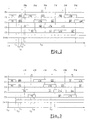
- FIG. 2 shows a diagram which illustrates the operation of the method according to the invention.
- PS prepositioning in which all the valves 18, 19 are open to the maximum, because this type of PS prepositioning communicates the intake circuit 16 with the exhaust circuit 17, which produces a phenomenon of "cross-flow", ie a invasion of the intake circuit 16 by the burnt gases, especially in the event of a warm start.
- the Dem starter which is supplied with electric current by a engine battery, so as to cause the rotation of the crankshaft 23.
- This INJ fuel injection is therefore not synchronized with the angular position of the crankshaft 23.
- the detection of the angular reference RA here means that the piston 14 of cylinder C1 is in its upward stroke, at near its top dead center TDC.
- the start-up phase which has just been described in reference to FIG. 2, constitutes a favorable start-up case because the angular position of the crankshaft 23 was determined from the first point PM of cylinder C1 following the launch of starter Dem.
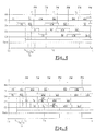
- FIG. 3 shows an unfavorable case of start in which the identification of the angular position only intervenes after approximately one revolution of the crankshaft 23.
- FIG. 4 shows an operating mode of the process when one detects at startup, at time t0, a low battery charge.
- the method according to the invention also includes a mode of special operation in case of hot start.
- the electronic unit 21 determines from sensors (not shown) if you are in a hot start case.
- the principle of operation in the purge mode M p consists in using the "no-load" rotation, therefore without fuel injection, of the crankshaft 23, by controlling the valves 18, 19 of the cylinder 10 in an adequate manner, to purge the circuit d admission 16 of the burnt gases which it contains, by evacuating them towards the exhaust circuit 17.
- the purge mode M p operates according to a two-phase cycle which is illustrated in FIG. 5.
- This two-phase cycle includes an admission phase Pa of the gases burned during the downward stroke of the piston 14 from TDC top dead center to TDC bottom dead center.
- the admission phase Pa is limited by the opening of the intake valve 18 near top dead center TDC and its closing in the vicinity of the bottom dead center PMB.
- the cylinder 10 therefore fills with burnt gases which are initially contained in the intake circuit 16.
- the second phase is a gas evacuation phase Pe burnt which takes place during the upward stroke of the piston 14 from PMB bottom dead center up to PMB top dead center.
- the evacuation phase Pe is limited by the opening OE of the exhaust valve 19 near the bottom dead center PMB, after closing FA of the intake valve 18, and the FE closure of the exhaust valve 19 in the vicinity of the top dead center TDC, before valve opening OA of admission 18.
- the cylinder 10 therefore empties the burnt gases which it contains in the exhaust circuit 17.
- the succession of closures FA, FE and of the openings OA, OE of valves 18, 19 is made the most quickly possible given the technical possibilities of control system for valves 18, 19 and the system which provides energy, for example the battery.
- This type of operation makes it possible in particular to reduce the energy consumption required to open and closing valves 18, 19.
- FIG. 6 shows an example of operation of the method according to the invention in the case of starting hot.
- the piston 14 of the cylinder C3 After its prepositioning PS, the piston 14 of the cylinder C3 is here in its downstroke, therefore it begins its operation in Mp purge mode with a gas intake phase Pa then, during the upstroke of its piston 14, it performs a gas evacuation phase Pe.
- the INJ injection being here of the indirect type, it can take place during the evacuation phase Pe of the C3 cylinder operation in Mp purge mode
- each secondary cylinder C2, C3 has a single phase admission Pa and a single evacuation phase Pe.
- the fuel injection INJ is suspended in cylinders C1, C2, C3, C4 having already had a phase INJ fuel injection.
Landscapes
- Engineering & Computer Science (AREA)
- Mechanical Engineering (AREA)
- General Engineering & Computer Science (AREA)
- Chemical & Material Sciences (AREA)
- Combustion & Propulsion (AREA)
- Electrical Control Of Air Or Fuel Supplied To Internal-Combustion Engine (AREA)
- Output Control And Ontrol Of Special Type Engine (AREA)
- Combined Controls Of Internal Combustion Engines (AREA)
Abstract
Description
- pour un premier groupe de cylindres, ou cylindres primaires, on
réalise successivement les opérations suivantes :
- avant le lancement du démarreur, on commande un prépositionnement des soupapes au cours duquel on commande le déplacement de toutes les soupapes dans une position fermée ou dans une position ouverte au maximum ;
- après le lancement du démarreur, on commande la première injection de carburant dans au moins un cylindre primaire, sans attendre la détermination de la position angulaire du vilebrequin ;
- dès que l'on a déterminé la position angulaire du vilebrequin, on synchronise l'allumage et la position des soupapes par rapport à la position angulaire du vilebrequin en vue de fonctionner selon le cycle classique à quatre temps du moteur ;
- pour un second groupe de cylindres, ou cylindres secondaires,
on réalise les opérations suivantes
- - après le lancement du démarreur, on commande pour chaque cylindre secondaire l'un après l'autre, un prépositionnement des soupapes au cours duquel on commande le déplacement de toutes les soupapes dans une position fermée ou dans une position ouverte au maximum ;
- - pour chaque cylindre secondaire, lorsque le prépositionnement des soupapes est effectué, et lorsque l'on a déterminé la position angulaire du vilebrequin, on commande son fonctionnement selon le cycle classique.
- on commande simultanément la première injection de carburant dans tous les cylindres primaires, sans attendre la détermination de la position angulaire du vilebrequin ;
- lorsque l'on commande le prépositionnement des soupapes des cylindres primaires et secondaires, soit on ferme les soupapes d'admission et on ouvre au maximum les soupapes d'échappement, soit on ouvre au maximum les soupapes d'admission et on ferme les soupapes d'échappement ;
- en phase de démarrage du moteur à chaud, pour au
moins un cylindre secondaire, après avoir commandé le
prépositionnement de ses soupapes, et avant de commander son
fonctionnement en mode classique, on commande son
fonctionnement dans un mode dit de purge dans lequel on
commande successivement :
- au voisinage du point mort haut du piston, la fermeture des soupapes d'échappement et l'ouverture d'au moins une soupape d'admission ;
- au voisinage du point mort bas du piston, la fermeture
des soupapes d'admission et l'ouverture d'au moins une soupape
d'échappement, de manière à transvaser vers le circuit
d'échappement au moins une partie des gaz brûlés qui ont rempli
le circuit d'admission pendant l'arrêt du moteur ;
- - pour les cylindres secondaires fonctionnant en mode de purge, on commande le prépositionnement des soupapes après avoir déterminé la position angulaire du vilebrequin, et on positionne les soupapes en fonction de la position du piston dans le cylindre, de manière que le cylindre soit prêt à fonctionner en mode de purge au point mort suivant du piston ;
- - en cas d'échecs successifs du démarrage, on suspend l'injection de carburant pour les cylindres ayant déjà eu une phase d'injection ;
- - si l'on détecte une faible charge de la batterie avant le démarrage, on décale dans le temps le prépositionnement des soupapes de chaque cylindre primaire par rapport aux prépositionnements des autres cylindres primaires, en vue de lisser dans le temps la consommation de courant électrique nécessaire à ces prépositionnements ;
- - pour chaque cylindre secondaire, on commande la première injection de carburant après le prépositionnement de ses soupapes, sans attendre d'être en phase avec le cycle classique.
- la figure 1 est une vue schématique partielle en coupe d'une partie d'un moteur à combustion interne à soupapes sans arbres à cames et commandé selon un procédé conforme aux enseignements de l'invention ;
- la figure 2 est un diagramme qui illustre le fonctionnement du procédé selon l'invention dans le cas d'un démarrage favorable ;
- la figure 3 est un diagramme qui illustre le fonctionnement du procédé selon l'invention dans le cas d'un démarrage défavorable ;
- la figure 4 est un diagramme qui illustre le fonctionnement du procédé selon l'invention lorsque l'on détecte une faible charge de la batterie au démarrage ;
- la figure 5 est un diagramme qui illustre le fonctionnement d'un cylindre en mode de purge ; et
- la figure 6 est un diagramme qui illustre le fonctionnement du procédé selon l'invention en cas de démarrage à chaud.
Claims (8)
- Procédé de commande d'un moteur à combustion à quatre temps à injection, en vue d'optimiser la durée du démarrage et en vue d'étaler dans le temps la consommation d'énergie électrique pendant le démarrage, dans lequel l'ouverture et la fermeture de chaque soupape (18, 19) est commandée par un actionneur linéaire électromagnétique (11, 13), relié à une unité électronique de commande (21).
caractérisé en ce que, lorsque le démarrage du moteur a été demandé,pour un premier groupe de cylindres, ou cylindres primaires (C1, C4), on réalise successivement les opérations suivantes :avant le lancement du démarreur (Dem), on commande un prépositionnement (PS) des soupapes (18, 19) au cours duquel on commande le déplacement de toutes les soupapes (18, 19) dans une position fermée ou dans une position ouverte au maximum ;après le lancement du démarreur (Dem), on commande la première injection (INJ) de carburant dans au moins un cylindre primaire (C1, C4), sans attendre la détermination de la position angulaire du vilebrequin (23) ;dès que l'on a déterminé la position angulaire du vilebrequin (23), on synchronise l'allumage (ALL) et la position des soupapes (18, 19) par rapport à la position angulaire du vilebrequin (23) en vue de fonctionner selon le cycle classique à quatre temps du moteur ;pour un second groupe de cylindres, ou cylindres secondaires (C2, C3), on réalise les opérations suivantes :après le lancement du démarreur Dem, on commande pour chaque cylindre secondaire (C2, C3) l'un après l'autre, un prépositionnement (PS) des soupapes (18, 19) au cours duquel on commande le déplacement de toutes les soupapes (18, 19) dans une position fermée ou dans une position ouverte au maximum ;pour chaque cylindre secondaire (C2, C3), lorsque le prépositionnement (PS) des soupapes (18, 19) est effectué, et lorsque l'on a déterminé la position angulaire du vilebrequin (23), on commande son fonctionnement selon le cycle classique. - Procédé selon la revendication précédente, caractérisé en ce que l'on commande simultanément la première injection (INJ) de carburant dans tous les cylindres primaires (C1, C4), sans attendre la détermination de la position angulaire du vilebrequin (23).
- Procédé selon l'une quelconque des revendications précédentes, caractérisé en ce que, lorsque l'on commande le prépositionnement (Ps) des soupapes (18, 19) des cylindres primaires (C1, C4) et secondaires (C2, C3), soit on ferme les soupapes d'admission (18) et on ouvre au maximum les soupapes d'échappement (19), soit on ouvre au maximum les soupapes d'admission (18) et on ferme les soupapes d'échappement (19).
- Procédé selon la revendication précédente, caractérisé en ce que, en phase de démarrage du moteur à chaud, pour au moins un cylindre secondaire (C2, C3), après avoir commandé le prépositionnement (PS) de ses soupapes (18, 19), et avant de commander son fonctionnement en mode classique, on commande son fonctionnement dans un mode dit de purge (Mp) dans lequel on commande successivement :au voisinage du point mort haut (PMH) du piston (14), la fermeture (FE) des soupapes d'échappement (19) et l'ouverture (OA) d'au moins une soupape d'admission (18) ;au voisinage du point mort bas (PMB) du piston (14), la fermeture (FA) des soupapes d'admission (18) et l'ouverture d'au moins une soupape d'échappement (OE), de manière à transvaser vers le circuit d'échappement (17) au moins une partie (16) des gaz brûlés qui ont rempli le circuit d'admission (16) pendant l'arrêt du moteur.
- Procédé selon la revendication précédente, caractérisé en ce que, pour les cylindres secondaires (C2, C3) fonctionnant en mode de purge (Mp), on commande le prépositionnement (PS) des soupapes (18, 19) après avoir déterminé la position angulaire du vilebrequin (23), et on positionne les soupapes (18, 19) en fonction de la position du piston (14) dans le cylindre (C2, C3), de manière que le cylindre (C2, C3) soit prêt à fonctionner en mode de purge (Mp) au point mort (PM) suivant du piston (14).
- Procédé selon l'une quelconque des revendications précédentes, caractérisé en ce qu'en cas d'échecs successifs du démarrage, on suspend l'injection (INJ) de carburant pour les cylindres (C1, C2, C3, C4) ayant déjà eu une phase d'injection (INJ).
- Procédé selon l'une quelconque des revendications précédentes, caractérisé en ce que, si l'on détecte une faible charge de la batterie avant le démarrage, on décale dans le temps le prépositionnement (PS) des soupapes (18, 19) de chaque cylindre primaire (C1, C4) par rapport aux prépositionnements (PS) des autres cylindres primaires (C1, C4), en vue de lisser dans le temps la consommation de courant électrique nécessaire à ces prépositionnements (PS).
- Procédé selon l'une quelconque des revendications précédentes, caractérisé en ce que, pour chaque cylindre secondaire (C2, C3), on commande la première injection (INJ) de carburant après le prépositionnement (PS) de ses soupapes (18, 19), sans attendre d'être en phase avec le cycle classique.
Applications Claiming Priority (2)
| Application Number | Priority Date | Filing Date | Title |
|---|---|---|---|
| FR0015170A FR2817292B1 (fr) | 2000-11-24 | 2000-11-24 | Procede de commande d'un moteur a combustion en vue d'optimiser le demarrage |
| FR0015170 | 2000-11-24 |
Publications (2)
| Publication Number | Publication Date |
|---|---|
| EP1209341A1 true EP1209341A1 (fr) | 2002-05-29 |
| EP1209341B1 EP1209341B1 (fr) | 2006-01-11 |
Family
ID=8856826
Family Applications (1)
| Application Number | Title | Priority Date | Filing Date |
|---|---|---|---|
| EP01403004A Expired - Lifetime EP1209341B1 (fr) | 2000-11-24 | 2001-11-23 | Procédé de commande d'un moteur à combustion en vue d'optimiser le démarrage |
Country Status (4)
| Country | Link |
|---|---|
| EP (1) | EP1209341B1 (fr) |
| DE (1) | DE60116588T2 (fr) |
| ES (1) | ES2251447T3 (fr) |
| FR (1) | FR2817292B1 (fr) |
Cited By (4)
| Publication number | Priority date | Publication date | Assignee | Title |
|---|---|---|---|---|
| FR2900447A1 (fr) * | 2006-04-26 | 2007-11-02 | Valeo Sys Controle Moteur Sas | Procede de demarrage d'un moteur thermique par allumage simultane dans deux cylindres |
| EP1577509A3 (fr) * | 2004-03-19 | 2008-12-10 | Ford Global Technologies, LLC | Procédé de contrôle d'une soupape à commande électromécanique basé sur un système électrique du véhicule |
| US7650745B2 (en) | 2004-03-19 | 2010-01-26 | Ford Global Technologies, Llc | Method to reduce engine emissions for an engine capable of multi-stroke operation and having a catalyst |
| EP1577543A3 (fr) * | 2004-03-19 | 2010-06-30 | Ford Global Technologies, LLC | Procédé de démarrage à froid pour moteur à combustion interne avec soupapes à commande électromagnétique |
Families Citing this family (4)
| Publication number | Priority date | Publication date | Assignee | Title |
|---|---|---|---|---|
| US6997146B2 (en) * | 2002-05-22 | 2006-02-14 | Toyota Jidosha Kabushiki Kaisha | Start control method and apparatus for solenoid-operated valves of internal combustion engine |
| US7021289B2 (en) | 2004-03-19 | 2006-04-04 | Ford Global Technology, Llc | Reducing engine emissions on an engine with electromechanical valves |
| US7383820B2 (en) | 2004-03-19 | 2008-06-10 | Ford Global Technologies, Llc | Electromechanical valve timing during a start |
| US7072758B2 (en) | 2004-03-19 | 2006-07-04 | Ford Global Technologies, Llc | Method of torque control for an engine with valves that may be deactivated |
Citations (4)
| Publication number | Priority date | Publication date | Assignee | Title |
|---|---|---|---|---|
| DE19851214C1 (de) * | 1998-11-06 | 1999-11-04 | Daimler Chrysler Ag | Verfahren zum Betrieb der Brennkraftmaschine eines Kraftfahrzeugs |
| JPH11324744A (ja) * | 1998-05-19 | 1999-11-26 | Fuji Heavy Ind Ltd | 電磁駆動バルブの始動時制御装置 |
| US6092496A (en) * | 1998-09-04 | 2000-07-25 | Caterpillar Inc. | Cold starting method for diesel engine with variable valve timing |
| DE10009320A1 (de) * | 1999-03-04 | 2000-09-14 | Honda Motor Co Ltd | Steuersystem für einen Verbrennungsmotor |
Family Cites Families (1)
| Publication number | Priority date | Publication date | Assignee | Title |
|---|---|---|---|---|
| DE9420463U1 (de) | 1994-12-21 | 1996-04-25 | FEV Motorentechnik GmbH & Co. KG, 52078 Aachen | Elektromagnetisch betätigbare Stellvorrichtung |
-
2000
- 2000-11-24 FR FR0015170A patent/FR2817292B1/fr not_active Expired - Fee Related
-
2001
- 2001-11-23 ES ES01403004T patent/ES2251447T3/es not_active Expired - Lifetime
- 2001-11-23 DE DE60116588T patent/DE60116588T2/de not_active Expired - Lifetime
- 2001-11-23 EP EP01403004A patent/EP1209341B1/fr not_active Expired - Lifetime
Patent Citations (4)
| Publication number | Priority date | Publication date | Assignee | Title |
|---|---|---|---|---|
| JPH11324744A (ja) * | 1998-05-19 | 1999-11-26 | Fuji Heavy Ind Ltd | 電磁駆動バルブの始動時制御装置 |
| US6092496A (en) * | 1998-09-04 | 2000-07-25 | Caterpillar Inc. | Cold starting method for diesel engine with variable valve timing |
| DE19851214C1 (de) * | 1998-11-06 | 1999-11-04 | Daimler Chrysler Ag | Verfahren zum Betrieb der Brennkraftmaschine eines Kraftfahrzeugs |
| DE10009320A1 (de) * | 1999-03-04 | 2000-09-14 | Honda Motor Co Ltd | Steuersystem für einen Verbrennungsmotor |
Non-Patent Citations (1)
| Title |
|---|
| PATENT ABSTRACTS OF JAPAN vol. 2000, no. 02 29 February 2000 (2000-02-29) * |
Cited By (5)
| Publication number | Priority date | Publication date | Assignee | Title |
|---|---|---|---|---|
| EP1577509A3 (fr) * | 2004-03-19 | 2008-12-10 | Ford Global Technologies, LLC | Procédé de contrôle d'une soupape à commande électromécanique basé sur un système électrique du véhicule |
| US7650745B2 (en) | 2004-03-19 | 2010-01-26 | Ford Global Technologies, Llc | Method to reduce engine emissions for an engine capable of multi-stroke operation and having a catalyst |
| EP1577543A3 (fr) * | 2004-03-19 | 2010-06-30 | Ford Global Technologies, LLC | Procédé de démarrage à froid pour moteur à combustion interne avec soupapes à commande électromagnétique |
| US8191355B2 (en) | 2004-03-19 | 2012-06-05 | Ford Global Technologies, Llc | Method to reduce engine emissions for an engine capable of multi-stroke operation and having a catalyst |
| FR2900447A1 (fr) * | 2006-04-26 | 2007-11-02 | Valeo Sys Controle Moteur Sas | Procede de demarrage d'un moteur thermique par allumage simultane dans deux cylindres |
Also Published As
| Publication number | Publication date |
|---|---|
| EP1209341B1 (fr) | 2006-01-11 |
| FR2817292B1 (fr) | 2003-01-24 |
| DE60116588T2 (de) | 2006-08-10 |
| DE60116588D1 (de) | 2006-04-06 |
| ES2251447T3 (es) | 2006-05-01 |
| FR2817292A1 (fr) | 2002-05-31 |
Similar Documents
| Publication | Publication Date | Title |
|---|---|---|
| EP1195505A1 (fr) | Procédé de contrôle d'auto-allumage dans un moteur à quatre temps | |
| EP1209341B1 (fr) | Procédé de commande d'un moteur à combustion en vue d'optimiser le démarrage | |
| FR2797304A1 (fr) | Procede de commande d'un moteur a combustion en vue de faciliter le demarrage du moteur apres un arret | |
| JP4823215B2 (ja) | 内燃機関の1グループのシリンダの動作の制御方法 | |
| FR2893676A1 (fr) | Procede pour controler l'admission et/ou l'echappement d'au moins un cylindre desactive d'un moteur a combustion interne | |
| JP6791359B2 (ja) | エンジンの制御装置 | |
| EP2077382B1 (fr) | Procédé pour démarrer à froid un moteur à combustion interne, notamment à autoallumage, et moteur utilisant un tel procédé | |
| EP1544434B1 (fr) | Procédé de commande d'un moteur à combustion interne suralimenté | |
| FR2916799A1 (fr) | Procede et dispositif de commande de soupape avec plusieurs phases de levee, procede d'alimentation d'un moteur | |
| EP1069298B1 (fr) | Procédé de commande d'un moteur à combustion en vue de compenser la défaillance d'une soupape | |
| EP1138885B1 (fr) | Procédé de commande d'un moteur à combustion en vue de faciliter le démarrage | |
| EP1740808A2 (fr) | Procede de commande du fonctionnement d'un cylindre de moteur a combustion interne | |
| EP1384862B1 (fr) | Procédé et dispositif de contrôle de moteur à combustion interne | |
| FR2795133A1 (fr) | Procede de commande d'un moteur a combustion en vue de l'obtention d'un effet de frein moteur | |
| EP1384863B1 (fr) | Moteur à combustion interne comprenant un processeur et des actionneurs électromécaniques de commande de soupapes | |
| WO2006084660A1 (fr) | Procede pour controler le demarrage d’un moteur a combustion interne | |
| EP1384861B1 (fr) | Moteur à combustion interne muni d'un processeur et d'actionneurs électromécaniques de commande de soupapes | |
| EP2674601A1 (fr) | Procédé de balayage des gaz brûlés résiduels par double levée de soupapes pour un moteur à deux temps, notamment de type Diesel. | |
| EP1408202A2 (fr) | Moteur à combustion interne muni d'un processeur et de cylindres dont chacun comporte au moins deux soupapes d'admission à commande électromécanique | |
| EP2201233A2 (fr) | Moteur a combustion interne a chambre de combustion a geometrie variable | |
| FR2652124A1 (fr) | Procede et appareil pour refouler a force de l'air dans un moteur a combustion interne apres la phase de combustion. | |
| FR2939476A1 (fr) | Procede pour controler le fonctionnement d'un moteur a combustion interne avec desactivation d'au moins un cylindre | |
| FR2938880A1 (fr) | Moteur a recirculation de gaz d'echappement et vehicule comprenant le moteur | |
| FR2904049A1 (fr) | Moteur thermique ayant deux conduits d'admission dont l'un est utilise pour balayer la chambre de combustion, module de gestion d'un tel moteur thermique et procede de gestion d'un moteur thermique | |
| FR2922952A1 (fr) | Procede de controle de la cylindree d'un moteur a combustion interne. |
Legal Events
| Date | Code | Title | Description |
|---|---|---|---|
| PUAI | Public reference made under article 153(3) epc to a published international application that has entered the european phase |
Free format text: ORIGINAL CODE: 0009012 |
|
| AK | Designated contracting states |
Kind code of ref document: A1 Designated state(s): AT BE CH CY DE DK ES FI FR GB GR IE IT LI LU MC NL PT SE TR |
|
| AX | Request for extension of the european patent |
Free format text: AL;LT;LV;MK;RO;SI |
|
| RAP1 | Party data changed (applicant data changed or rights of an application transferred) |
Owner name: RENAULT S.A.S. |
|
| AKX | Designation fees paid | ||
| 17P | Request for examination filed |
Effective date: 20021113 |
|
| RBV | Designated contracting states (corrected) |
Designated state(s): BE DE ES GB |
|
| REG | Reference to a national code |
Ref country code: DE Ref legal event code: 8566 |
|
| GRAP | Despatch of communication of intention to grant a patent |
Free format text: ORIGINAL CODE: EPIDOSNIGR1 |
|
| GRAS | Grant fee paid |
Free format text: ORIGINAL CODE: EPIDOSNIGR3 |
|
| GRAA | (expected) grant |
Free format text: ORIGINAL CODE: 0009210 |
|
| AK | Designated contracting states |
Kind code of ref document: B1 Designated state(s): BE DE ES GB |
|
| GBT | Gb: translation of ep patent filed (gb section 77(6)(a)/1977) |
Effective date: 20060222 |
|
| REF | Corresponds to: |
Ref document number: 60116588 Country of ref document: DE Date of ref document: 20060406 Kind code of ref document: P |
|
| REG | Reference to a national code |
Ref country code: ES Ref legal event code: FG2A Ref document number: 2251447 Country of ref document: ES Kind code of ref document: T3 |
|
| PLBE | No opposition filed within time limit |
Free format text: ORIGINAL CODE: 0009261 |
|
| STAA | Information on the status of an ep patent application or granted ep patent |
Free format text: STATUS: NO OPPOSITION FILED WITHIN TIME LIMIT |
|
| 26N | No opposition filed |
Effective date: 20061012 |
|
| PGFP | Annual fee paid to national office [announced via postgrant information from national office to epo] |
Ref country code: DE Payment date: 20141119 Year of fee payment: 14 Ref country code: ES Payment date: 20141126 Year of fee payment: 14 Ref country code: GB Payment date: 20141119 Year of fee payment: 14 |
|
| PGFP | Annual fee paid to national office [announced via postgrant information from national office to epo] |
Ref country code: BE Payment date: 20141118 Year of fee payment: 14 |
|
| REG | Reference to a national code |
Ref country code: DE Ref legal event code: R119 Ref document number: 60116588 Country of ref document: DE |
|
| GBPC | Gb: european patent ceased through non-payment of renewal fee |
Effective date: 20151123 |
|
| PG25 | Lapsed in a contracting state [announced via postgrant information from national office to epo] |
Ref country code: GB Free format text: LAPSE BECAUSE OF NON-PAYMENT OF DUE FEES Effective date: 20151123 Ref country code: DE Free format text: LAPSE BECAUSE OF NON-PAYMENT OF DUE FEES Effective date: 20160601 |
|
| PG25 | Lapsed in a contracting state [announced via postgrant information from national office to epo] |
Ref country code: ES Free format text: LAPSE BECAUSE OF NON-PAYMENT OF DUE FEES Effective date: 20151124 |
|
| PG25 | Lapsed in a contracting state [announced via postgrant information from national office to epo] |
Ref country code: BE Free format text: LAPSE BECAUSE OF NON-PAYMENT OF DUE FEES Effective date: 20151130 |
|
| REG | Reference to a national code |
Ref country code: ES Ref legal event code: FD2A Effective date: 20180710 |