EP1208972A1 - Method of lithographic printing with a reusable substrate. - Google Patents
Method of lithographic printing with a reusable substrate. Download PDFInfo
- Publication number
- EP1208972A1 EP1208972A1 EP00204090A EP00204090A EP1208972A1 EP 1208972 A1 EP1208972 A1 EP 1208972A1 EP 00204090 A EP00204090 A EP 00204090A EP 00204090 A EP00204090 A EP 00204090A EP 1208972 A1 EP1208972 A1 EP 1208972A1
- Authority
- EP
- European Patent Office
- Prior art keywords
- micro
- emulsion
- printing
- plate
- ink
- Prior art date
- Legal status (The legal status is an assumption and is not a legal conclusion. Google has not performed a legal analysis and makes no representation as to the accuracy of the status listed.)
- Granted
Links
Classifications
-
- C—CHEMISTRY; METALLURGY
- C11—ANIMAL OR VEGETABLE OILS, FATS, FATTY SUBSTANCES OR WAXES; FATTY ACIDS THEREFROM; DETERGENTS; CANDLES
- C11D—DETERGENT COMPOSITIONS; USE OF SINGLE SUBSTANCES AS DETERGENTS; SOAP OR SOAP-MAKING; RESIN SOAPS; RECOVERY OF GLYCEROL
- C11D17/00—Detergent materials or soaps characterised by their shape or physical properties
- C11D17/0008—Detergent materials or soaps characterised by their shape or physical properties aqueous liquid non soap compositions
- C11D17/0017—Multi-phase liquid compositions
- C11D17/0021—Aqueous microemulsions
-
- B—PERFORMING OPERATIONS; TRANSPORTING
- B41—PRINTING; LINING MACHINES; TYPEWRITERS; STAMPS
- B41C—PROCESSES FOR THE MANUFACTURE OR REPRODUCTION OF PRINTING SURFACES
- B41C1/00—Forme preparation
- B41C1/10—Forme preparation for lithographic printing; Master sheets for transferring a lithographic image to the forme
- B41C1/1008—Forme preparation for lithographic printing; Master sheets for transferring a lithographic image to the forme by removal or destruction of lithographic material on the lithographic support, e.g. by laser or spark ablation; by the use of materials rendered soluble or insoluble by heat exposure, e.g. by heat produced from a light to heat transforming system; by on-the-press exposure or on-the-press development, e.g. by the fountain of photolithographic materials
- B41C1/1025—Forme preparation for lithographic printing; Master sheets for transferring a lithographic image to the forme by removal or destruction of lithographic material on the lithographic support, e.g. by laser or spark ablation; by the use of materials rendered soluble or insoluble by heat exposure, e.g. by heat produced from a light to heat transforming system; by on-the-press exposure or on-the-press development, e.g. by the fountain of photolithographic materials using materials comprising a polymeric matrix containing a polymeric particulate material, e.g. hydrophobic heat coalescing particles
-
- B—PERFORMING OPERATIONS; TRANSPORTING
- B41—PRINTING; LINING MACHINES; TYPEWRITERS; STAMPS
- B41N—PRINTING PLATES OR FOILS; MATERIALS FOR SURFACES USED IN PRINTING MACHINES FOR PRINTING, INKING, DAMPING, OR THE LIKE; PREPARING SUCH SURFACES FOR USE AND CONSERVING THEM
- B41N3/00—Preparing for use and conserving printing surfaces
- B41N3/06—Preparing for use and conserving printing surfaces by use of detergents
-
- C—CHEMISTRY; METALLURGY
- C11—ANIMAL OR VEGETABLE OILS, FATS, FATTY SUBSTANCES OR WAXES; FATTY ACIDS THEREFROM; DETERGENTS; CANDLES
- C11D—DETERGENT COMPOSITIONS; USE OF SINGLE SUBSTANCES AS DETERGENTS; SOAP OR SOAP-MAKING; RESIN SOAPS; RECOVERY OF GLYCEROL
- C11D1/00—Detergent compositions based essentially on surface-active compounds; Use of these compounds as a detergent
- C11D1/02—Anionic compounds
-
- C—CHEMISTRY; METALLURGY
- C11—ANIMAL OR VEGETABLE OILS, FATS, FATTY SUBSTANCES OR WAXES; FATTY ACIDS THEREFROM; DETERGENTS; CANDLES
- C11D—DETERGENT COMPOSITIONS; USE OF SINGLE SUBSTANCES AS DETERGENTS; SOAP OR SOAP-MAKING; RESIN SOAPS; RECOVERY OF GLYCEROL
- C11D1/00—Detergent compositions based essentially on surface-active compounds; Use of these compounds as a detergent
- C11D1/02—Anionic compounds
- C11D1/04—Carboxylic acids or salts thereof
- C11D1/06—Ether- or thioether carboxylic acids
-
- C—CHEMISTRY; METALLURGY
- C11—ANIMAL OR VEGETABLE OILS, FATS, FATTY SUBSTANCES OR WAXES; FATTY ACIDS THEREFROM; DETERGENTS; CANDLES
- C11D—DETERGENT COMPOSITIONS; USE OF SINGLE SUBSTANCES AS DETERGENTS; SOAP OR SOAP-MAKING; RESIN SOAPS; RECOVERY OF GLYCEROL
- C11D1/00—Detergent compositions based essentially on surface-active compounds; Use of these compounds as a detergent
- C11D1/02—Anionic compounds
- C11D1/12—Sulfonic acids or sulfuric acid esters; Salts thereof
- C11D1/123—Sulfonic acids or sulfuric acid esters; Salts thereof derived from carboxylic acids, e.g. sulfosuccinates
-
- C—CHEMISTRY; METALLURGY
- C11—ANIMAL OR VEGETABLE OILS, FATS, FATTY SUBSTANCES OR WAXES; FATTY ACIDS THEREFROM; DETERGENTS; CANDLES
- C11D—DETERGENT COMPOSITIONS; USE OF SINGLE SUBSTANCES AS DETERGENTS; SOAP OR SOAP-MAKING; RESIN SOAPS; RECOVERY OF GLYCEROL
- C11D1/00—Detergent compositions based essentially on surface-active compounds; Use of these compounds as a detergent
- C11D1/02—Anionic compounds
- C11D1/12—Sulfonic acids or sulfuric acid esters; Salts thereof
- C11D1/29—Sulfates of polyoxyalkylene ethers
-
- C—CHEMISTRY; METALLURGY
- C11—ANIMAL OR VEGETABLE OILS, FATS, FATTY SUBSTANCES OR WAXES; FATTY ACIDS THEREFROM; DETERGENTS; CANDLES
- C11D—DETERGENT COMPOSITIONS; USE OF SINGLE SUBSTANCES AS DETERGENTS; SOAP OR SOAP-MAKING; RESIN SOAPS; RECOVERY OF GLYCEROL
- C11D3/00—Other compounding ingredients of detergent compositions covered in group C11D1/00
- C11D3/16—Organic compounds
- C11D3/18—Hydrocarbons
-
- C—CHEMISTRY; METALLURGY
- C11—ANIMAL OR VEGETABLE OILS, FATS, FATTY SUBSTANCES OR WAXES; FATTY ACIDS THEREFROM; DETERGENTS; CANDLES
- C11D—DETERGENT COMPOSITIONS; USE OF SINGLE SUBSTANCES AS DETERGENTS; SOAP OR SOAP-MAKING; RESIN SOAPS; RECOVERY OF GLYCEROL
- C11D3/00—Other compounding ingredients of detergent compositions covered in group C11D1/00
- C11D3/16—Organic compounds
- C11D3/20—Organic compounds containing oxygen
- C11D3/2068—Ethers
-
- B—PERFORMING OPERATIONS; TRANSPORTING
- B41—PRINTING; LINING MACHINES; TYPEWRITERS; STAMPS
- B41C—PROCESSES FOR THE MANUFACTURE OR REPRODUCTION OF PRINTING SURFACES
- B41C2210/00—Preparation or type or constituents of the imaging layers, in relation to lithographic printing forme preparation
- B41C2210/04—Negative working, i.e. the non-exposed (non-imaged) areas are removed
-
- B—PERFORMING OPERATIONS; TRANSPORTING
- B41—PRINTING; LINING MACHINES; TYPEWRITERS; STAMPS
- B41C—PROCESSES FOR THE MANUFACTURE OR REPRODUCTION OF PRINTING SURFACES
- B41C2210/00—Preparation or type or constituents of the imaging layers, in relation to lithographic printing forme preparation
- B41C2210/08—Developable by water or the fountain solution
-
- B—PERFORMING OPERATIONS; TRANSPORTING
- B41—PRINTING; LINING MACHINES; TYPEWRITERS; STAMPS
- B41C—PROCESSES FOR THE MANUFACTURE OR REPRODUCTION OF PRINTING SURFACES
- B41C2210/00—Preparation or type or constituents of the imaging layers, in relation to lithographic printing forme preparation
- B41C2210/22—Preparation or type or constituents of the imaging layers, in relation to lithographic printing forme preparation characterised by organic non-macromolecular additives, e.g. dyes, UV-absorbers, plasticisers
-
- B—PERFORMING OPERATIONS; TRANSPORTING
- B41—PRINTING; LINING MACHINES; TYPEWRITERS; STAMPS
- B41C—PROCESSES FOR THE MANUFACTURE OR REPRODUCTION OF PRINTING SURFACES
- B41C2210/00—Preparation or type or constituents of the imaging layers, in relation to lithographic printing forme preparation
- B41C2210/24—Preparation or type or constituents of the imaging layers, in relation to lithographic printing forme preparation characterised by a macromolecular compound or binder obtained by reactions involving carbon-to-carbon unsaturated bonds, e.g. acrylics, vinyl polymers
-
- C—CHEMISTRY; METALLURGY
- C11—ANIMAL OR VEGETABLE OILS, FATS, FATTY SUBSTANCES OR WAXES; FATTY ACIDS THEREFROM; DETERGENTS; CANDLES
- C11D—DETERGENT COMPOSITIONS; USE OF SINGLE SUBSTANCES AS DETERGENTS; SOAP OR SOAP-MAKING; RESIN SOAPS; RECOVERY OF GLYCEROL
- C11D2111/00—Cleaning compositions characterised by the objects to be cleaned; Cleaning compositions characterised by non-standard cleaning or washing processes
- C11D2111/10—Objects to be cleaned
- C11D2111/14—Hard surfaces
- C11D2111/20—Industrial or commercial equipment, e.g. reactors, tubes or engines
Definitions
- the present invention relates to a method for treating a micro-emulsion that is used as a cleaning liquid in a method for recycling the lithographic substrate of a printing plate.
- ink and an aqueous fountain solution are supplied to the surface of a printing master that contains ink accepting (oleophilic) and water-accepting (hydrophilic) areas.
- the inked image pattern is then transferred from the surface of the master to a blanket cylinder having a compressible surface. From the blanket cylinder the image is impressed onto paper.
- the master is typically a printing plate that carries an image on a dimensionally stable substrate such as an aluminium sheet.
- the imaged aluminium plate is secured to the plate cylinder of a printing press by a mechanical lock-up mechanism that defines positional registration between the plate and the surface of the cylinder. After the end of the press run, the mechanical lock-up system is released so that the printing plate carrying the printed image can be removed and discarded and another printing plate can be positioned and locked into place. A new print job can then be started.
- Printing masters are generally obtained by the so-called computer-to-film method wherein each colour selection is transferred to graphic arts film using an image-setter. After processing, the film can be used as a mask for the exposure of an imaging material called plate precursor and after plate processing, a printing plate is obtained which can be used as a master. These steps are usually performed in dedicated exposure and processing equipment and the printing plates are then transported to the printing press and attached to the printing cylinder by press operators using a lock-up mechanism built into the cylinder itself. Although the attachment of the printing cylinder is generally a manual operation, robotic means have been developed for positioning and securing the printing plates.
- a printing plate precursor is mounted on a printing press, image-wise exposed, optionally developed, and then used as a printing master and finally removed from the press and disposed of, thus requiring a new plate material for each image.
- An example of this technology is the Heidelberg Model GTO-DI, manufactured by Heidelberg Druckmaschinen AG (Germany) which is described in detail in US 5,339,737.
- a drawback of this method is the need to use a new plate for each press run, thus increasing the cost of the printing process.
- a second type of on-press imaging systems the same lithographic substrate is used in a plurality of press runs (hereinafter called printing cycles).
- a heat-sensitive or photosensitive layer is coated on the lithographic substrate to make a printing plate precursor and after image-wise exposure and optional development a printing master is obtained.
- the ink-accepting areas of the printing master are removed from the lithographic substrate in a cleaning step so that the substrate is recycled and can be used in a next cycle of coating, exposing and printing without the need to mount a new plate on the cylinder. Examples of such on-press coating and on-press imaging systems are described in e.g.
- the coating comprises hydrophobic thermoplastic polymer particles in a hydrophilic binder.
- the known cleaning liquids typically contain solvents which are harmful to hoses, pumps and sealings and/or require a very thorough rinsing with water because these liquids are not compatible with the coating step in the next printing cycle.
- a typical lithographic surface is mechanically as well as chemically quite vulnerable.
- a lithographic surface consists generally of a micro-pore structure in order to obtain a good differentiation between the spreading properties of the ink and the fountain.
- Anodised aluminium plates comprise a lithographic surface containing one or more metal oxides on which absorption phenomena can take place. These metal oxides are very susceptible to chemical conversion into forms that are no longer lithographically active.
- micro-porosity of a lithographic surface is also highly susceptible to mechanical damage.
- ink and the coated imaging layer penetrate in the micro-pore structure, it is necessary to carry out a vigorous cleaning so as to avoid ghost images in the subsequent printing cycles, which are due to an incomplete removal of the previous image.
- a suitable cleaning liquid is a micro-emulsion of an organic compound in water.
- the cleaning liquid consumed in each cleaning step needs to be collected and its disposal represents a problem for the user.
- This object is realised by the method of claim 2.
- the micro-emulsion defined in claim 1 effectively removes the ink-accepting areas of the printing master. No ghost images are observed after several (>10) print cycles of coating, exposure, printing and cleaning. Rubber hoses and seals are not affected by the cleaning liquid. A simple heating step suffices for inducing a phase separation, so that the water of the used micro-emulsion can easily be recycled.
- micro-emulsion as used herein an emulsion is defined having a particle size of less than 1 ⁇ m and preferably less than 200nm.
- a method for treating a specified micro-emulsion comprising in a first step the heating of the micro-emulsion to a temperature above 50°C whereby an aqueous and an organic phase are obtained and in a second step the separating of the obtained phases.
- the heating can be performed by known methods such as a heat resistor, microwaves etc.
- the phases can be separated by the known liquid separation techniques e.g. membrane processes or diffusional separation processes, or the method described below while discussing FIG. 1.
- the micro-emulsion comprises a mixture of a cyclic organic compound containing at least one double bond, an alcohol, water and an emulsifying agent.
- Suitable examples of cyclic organic compounds having at least one double bond are: toluene, xylene, propylbenzene, 3-methyl-6-isopropyl-1,4-cyclo-hexadiene, 3-(1-methylpropylidene)-cyclohexene, 6-methyl-1-(1-methylethyl)-1,3-cyclohexadiene, 4-methyl-5-(1-methylethenyl)-cyclohexene, o-mentha-4,6-diene, o-mentha-2(8),3-diene, o-mentha-1(7),4-diene, 6-methyl-1-(1-methylethenyl)-cyclohexene, 1-methyl-5-(1-methylethyl)-1,4-cyclohexadiene, isosylves
- the alcohol is preferably an aliphatic alcoholether.
- aliphatic alcoholethers are: methoxypropanol, propoxyethanol, 2-butoxyethanol, propanol, 2-(propyloxy)ethanol, fenoxyethanol, benzylalcohol, butoxypropanol, ethoxypropanol, 1-isobutoxy-2-propanol, 1-isomethoxy-2-propanol, 1-propoxy-2-propanol, diacetone alcohol, tetrahydrofurfuryl alcohol, cathechol, trimethylolpropane, ethanediol, propanediol, and butanediol. Highly preferred is 2-butoxyethanol.
- the alcohol and cyclic compound are preferably present in an amount of 5 to 50 wt.% each and most preferably in an amount of 10 to 30 wt.% each.
- the emulsifying agent is preferably an anionic compound and/or preferably comprises an alkylene oxide chain. Suitable examples are Akypo OP80, Akypo RO90 (both commercially available from Chem-Y), Empicol ESC70 (commercially available from Albright & Wilson), Aerosol OT (commercially available from AM Cynamid).
- the emulsifying agent is preferably present in an amount of 5 to 50 wt.% and most preferably in an amount of 10 to 30 wt.%.
- the above alcohol may also function as a co-emulsifying agent.
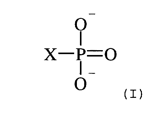
- micro-emulsion can comprise a compound according to formula I: wherein X is OH, O - or a polymer backbone.
- the counter ion can be, depending on the pH, H or a metal such as an alkali or alkaline earth metal or a transition metal, e.g. chromium.
- Suitable examples of the compound according to formula (I) are polyvinylphosphonic acid, copolymers of vinylphosphonic acid with acrylic acid and vinyl acetate, acrylamidoisobutylene phosphonic acid.
- the compound is phosphoric acid or a phosphate salt.
- the compound is preferably present in an amount of 1.5 to 6 wt.%.
- the micro-emulsion can be used in a method for removing ink-accepting areas of a lithographic printing master.
- the micro-emulsion is capable of removing the ink remaining on the printing areas as well as the hydrophobic coating itself that gives rise to the ink-accepting properties of the printing areas.
- the above micro-emulsion is very suitable for removing the ink-accepting areas from a printing master which is obtained by coating a hydrophilic substrate with a coating solution containing hydrophobic thermoplastic polymer particles and a hydrophilic binder.
- the imaging layer thus obtained is negative-working, i.e. hydrophobic areas are formed upon exposure. These areas define the printing areas of the master. It is believed that the applied heat induces a coagulation of the hydrophobic polymer particles, thereby forming a hydrophobic phase, whereas the hydrophobic polymer particles remain unchanged in the non-heated areas. Coagulation may result from heat-induced softening or melting of the thermoplastic polymer particles.
- the imaging layer which is preferably used in the present invention contains a coating comprising hydrophobic thermoplastic polymer particles having an average particle size between 40 nm and 2000 nm, and more preferably between 40 nm to 200 nm, so as to improve sensitivity and throughput and to avoid scumming.
- the polymer particles preferably have a coagulation temperature above 50°C and more preferably above 70°C. There is no specific upper limit to the coagulation temperature of the polymer particles, however the temperature should be sufficiently below the decomposition temperature of the polymer particles. Preferably the coagulation temperature is at least 10°C below the temperature at which the decomposition of the polymer particles occurs.
- thermoplastic hydrophobic polymer particles for use in the present invention have a Tg above 80°C.
- the weight average molecular weight of the polymers may range from 5,000 to 5,000,000 g/mol.
- the polymer particles are selected from the group consisting of polyvinyl chloride, polyvinylidene chloride, polyesters, polyurethanes, polyacrylonitrile, polyvinyl carbazole etc., and copolymers or mixtures thereof.
- the most preferred examples are polystyrene and polymethylmethacrylate or copolymers thereof.
- the polymer particles are present as a dispersion in the coating solution and may be prepared by the methods disclosed in US 3,476,937. Another method especially suitable for preparing an aqueous dispersion of the thermoplastic polymer particles comprises:
- Suitable hydrophilic binders for use in the present invention are preferably water-soluble (co)polymers for example synthetic homo- or copolymers such as polyvinylalcohol, a poly(meth)acrylic acid, a poly(meth)acrylamide, a polyhydroxyethyl(meth)acrylate, a polyvinylmethylether or natural binders such as gelatine, a polysaccharide such as e.g. dextran, pullulan, cellulose, arabic gum, alginic acid, inuline or chemically modified inuline.
- water-soluble (co)polymers for example synthetic homo- or copolymers such as polyvinylalcohol, a poly(meth)acrylic acid, a poly(meth)acrylamide, a polyhydroxyethyl(meth)acrylate, a polyvinylmethylether or natural binders such as gelatine, a polysaccharide such as e.g. dextran, pullulan
- the coating solution may also contain surfactants that can be anionic, cationic, non-ionic or amphoteric.
- Perfluoro surfactants are preferred. Particularly preferred are non-ionic perfluoro surfactants. Said surfactants can be used alone or preferably in combination.
- the coverage of the coated layer ranges preferably from 0.3 to 20 g/m 2 , more preferably from 0.5 to 5 g/m 2 .
- the amount of hydrophobic thermoplastic polymer particles contained in the coated layer is preferably between 50 and 90 wt.% and more preferably between 60 and 80 wt.% of the total weight of said layer.
- the coating solution is preferably applied to the substrate by spraying or jetting but other coating techniques may also be used.
- the substrate used in the present invention can be a plastic support or a ceramic but is preferably a metal such as aluminium.
- the substrate has a hydrophilic surface and is preferably characterised by a roughness value of at least 0.2 ⁇ m, more preferably of at least 0.3 ⁇ m, e.g. electrochemically and/or mechanically grained and anodised aluminium.
- the substrate can be a sheet-like material such as a plate but, alternatively, the coating solution may be applied directly to the plate cylinder of a rotary printing press, said cylinder thereby acting as the substrate.
- the lithographic substrate can also be a seamless sleeve printing plate, obtained by e.g. soldering a plate into a cylindrical form by means of a laser. The sleeve then can be slid around the plate cylinder instead of mounting a conventional printing plate. More details on sleeves are given in "Grafisch Nieuws" , 15, 1995, page 4 to 6.
- the exposure of the imaging layer obtained by coating the above coating solution on the lithographic substrate can be carried out by means of direct thermal recording using e.g. a thermal head, or by irradiation with high intensity light.
- the heat-sensitive material preferably comprises a compound capable of converting light into heat, preferably a compound having sufficient absorption in the wavelength range of the light source used for image-wise exposure.
- Particularly useful compounds are for example dyes and in particular infrared dyes as disclosed in EP-A 908 307 and pigments and in particular infrared pigments such as carbon black, metal carbides, borides, nitrides, carbonitrides, bronze-structured oxides and oxides structurally related to the bronze family but lacking the A component e.g.
- WO 2.9 It is also possible to use conductive polymer dispersions such as polypyrrole, polyaniline or polythiophene-based conductive polymer dispersions.
- conductive polymer dispersions such as polypyrrole, polyaniline or polythiophene-based conductive polymer dispersions.
- the lithographic performance and in particular the print endurance obtained depends i.a. on the heat-sensitivity of the imaging material. In this respect it has been found that carbon black yields very good and favourable results.
- Image-wise exposure in the method of the present invention is preferably an image-wise scanning exposure involving the use of a laser or L.E.D.
- a laser or L.E.D Preferably used are lasers that operate in the infrared or near-infrared, i.e. wavelength range of 700-1500 nm. Most preferred are laser diodes emitting in the near infrared.
- a grained and anodised aluminium plate is mounted on the plate cylinder of a rotary printing press.
- the coating solution described above is sprayed on the hydrophilic lithographic surface of the plate, so as to form a continuous imaging layer.
- Preferred values of the spraying parameters have been defined in EP-A no. 99203064 and EP-A no. 99203065, both filed on 15th September 1999.
- the imaging layer is then image-wise exposed by a laser device which is integrated in the printing press e.g.
- the cleaning step can be executed in a cleaning unit similar to the known blanket cleaning systems.
- a cloth is preferably moistened with the micro-emulsion, contacted with the printed plate during 1 to 50, more preferably during 2 to 10 revolutions with a contacting pressure between 10 4 and 6x10 5 Pa at a rotation speed in the range of 2 to 50 m/min. Afterwards the contact between the printing surface and the cleaning cloth is disrupted and the cloth is transported until a dry and clean part of the cloth is available.
- the micro-emulsion can also be applied by spraying, coating or jetting the liquid on the lithographic substrate or on the cloth.
- the removal of the ink-accepting areas can also be effected with another absorbing medium than a cloth.
- Cleaning can also be effected by combining the treatment with the micro-emulsion of the present invention with other means of mechanical cleaning such as a rotating brush or by jetting water or a volatile medium such as air, a solvent or dry ice pellets. Also vacuum extraction can be used during the cleaning treatment.
- the used micro-emulsion containing dissolved ink and hydrophobic coating is treated as described above.
- the obtained aqueous phase can be used for preparing fresh micro-emulsion or for rinsing the substrate before starting a new print cycle of coating, printing and cleaning.
- the steps of the method of the present invention are preferably performed on-press.
- the lithographic substrate can also be mounted on a drum in a dedicated coating apparatus (off-press coating) and subsequently be mounted on a plate setter for image-wise exposure (off-press exposure).
- the printing master thus obtained can be mounted on a press cylinder and printing is started by supplying ink and a fountain solution.
- the plate can be cleaned as described above, either on-press or in a dedicated cleaning apparatus, and the recycled substrate can then be used again in a next printing cycle.
- the used micro-emulsion can be collected and separated in a device that may be integrated in the printing press or in a stand-alone apparatus.
- a heating element (10) is constructed, able to maintain a constant temperature of 50°C.
- a conductivity measurement cell (5) is used to maintain the level of water lower than the outlet for the organic based compounds (7). This level is regulated both by a pump before the inlet (2) and a valve system after outlet (3) assures that the part (1) is filled with water and part (6) is filled with organic components.
- This system can be used in a discontinuous way, batchwise, but also in a continuous process by introducing plates (8) to avoid flowing of the micro-emulsion into the outlet (7).
- an printing apparatus comprising a print cylinder, means for mounting a reusable substrate having a hydrophilic surface to the print cylinder, means for coating an imaging layer onto the hydrophilic surface, means for image-wise exposing the imaging layer, means for applying ink and fountain solution to the print cylinder. Additionally the printing apparatus comprises means for supplying micro-emulsion to the print cylinder and means for treating the micro-emulsion as described above.
- a 0.30 mm thick aluminium foil was degreased by immersing the foil in an aqueous solution containing 5 g/l of sodium hydroxide at 50°C and rinsed with demineralized water.
- the foil was then electrochemically grained using an alternating current in an aqueous solution containing 4 g/l of hydrochloric acid, 4 g/l of hydroboric acid and 5 g/l of aluminium ions at a temperature of 35°C and a current density of 1200 A/m 2 to form a surface topography with an average centre-line roughness Ra of 0.5 ⁇ m.
- the aluminium foil was then etched with an aqueous solution containing 300 g/l of sulphuric acid at 60°C for 180 seconds and rinsed with demineralized water at 25°C for 30 seconds.
- the foil was subsequently subjected to anodic oxidation in an aqueous solution containing 200 g/l of sulphuric acid at a temperature of 45°C, a voltage of about 10 V and a current density of 150 A/m 2 for about 300 seconds to form an anodic oxidation film of 3.00 g/m 2 of Al 2 O 3 then washed with demineralized water, posttreated with a solution containing polyvinylphosphonic acid and subsequently with a solution containing aluminium trichloride, rinsed with demineralized water at 20°C during 120 seconds and dried.
- a 2.61% wt solution in water was prepared by mixing polystyrene latex, a heat absorbing compound and a hydrophilic binder. After spraying and drying, the resulting layer contained 75% wt. of the polystyrene latex, 10 % wt. of the heat absorbing compound, presented in formula (I) and 15% wt. polyacrylic acid (Glascol E15, commercially available at N.V. Allied Colloids Belgium).
- the spray solution was sprayed on above mentioned lithographic base. Therefore, the lithographic base was mounted on a drum, rotating at a line speed of 164 m/min.
- the imaging element was coated by a spray nozzle moving in transverse direction at a speed of 1.5 m/min.
- the spray nozzle was mounted at a distance of 80mm between nozzle and receiving substrate.
- the flow rate of the spray solution was set to 7 ml/min.
- an air pressure of 90 psi was used on the spray head. This layer was dried at a temperature of 70°C during the spraying process and additionally during 30 s.
- the spray nozzle was of the type SUJ1, an air assisted spray nozzle, commercially available from Spraying Systems Belgium, Brussels.
- the above mentioned heat mode imaging element was imaged in a Creo 3244TM external drum platesetter at 2400 dpi at 150 rpm with a power setting of 15.5 Watt.
- the imaged plates were printed on a GT046 printing press (from Heidelberger Druckmaschinen) with K+E 800 Skinnex ink, fountain (Combifix XL (4%) - isopropylalcohol (10%) in water) to a run length of 5000.
- the print quality was evaluated.
- dipentene (commercially available from Sigma-Aldrich) was mixed with 20 g of Akypo OP80. While stirring, 14 g of butoxyethanol as added. In the next step, 50 g of water was added while stirring.
- micro-emulsion A 10 ml/m 2 of micro-emulsion A was sprayed on the plate which still contained the adhered ink, using a manual pressure sprayer commercially available from Premal Sprayer Division of Precision Valve corporation, New York.
- the plate was cleaned by use of a standard high pressure washer, using a volume of water of 10 litre/m 2 .
- the used emulsion was collected and heated up to 50°C in an apparatus according to FIG.1. After 30s the organic compounds were completely separated from the water. The water was collected and used for rinsing substrates after the ink accepting areas were removed with micro-emulsion as described above. The substrates were then recoated with spray solution as described above.
Landscapes
- Chemical & Material Sciences (AREA)
- Engineering & Computer Science (AREA)
- Life Sciences & Earth Sciences (AREA)
- Chemical Kinetics & Catalysis (AREA)
- Oil, Petroleum & Natural Gas (AREA)
- Wood Science & Technology (AREA)
- Organic Chemistry (AREA)
- Emergency Medicine (AREA)
- Health & Medical Sciences (AREA)
- Physics & Mathematics (AREA)
- Optics & Photonics (AREA)
- Thermal Sciences (AREA)
- Manufacturing & Machinery (AREA)
- Printing Plates And Materials Therefor (AREA)
- Manufacture Or Reproduction Of Printing Formes (AREA)
- Photosensitive Polymer And Photoresist Processing (AREA)
Abstract
Description
- The present invention relates to a method for treating a micro-emulsion that is used as a cleaning liquid in a method for recycling the lithographic substrate of a printing plate.
- In conventional lithographic printing, ink and an aqueous fountain solution are supplied to the surface of a printing master that contains ink accepting (oleophilic) and water-accepting (hydrophilic) areas. The inked image pattern is then transferred from the surface of the master to a blanket cylinder having a compressible surface. From the blanket cylinder the image is impressed onto paper. The master is typically a printing plate that carries an image on a dimensionally stable substrate such as an aluminium sheet. The imaged aluminium plate is secured to the plate cylinder of a printing press by a mechanical lock-up mechanism that defines positional registration between the plate and the surface of the cylinder. After the end of the press run, the mechanical lock-up system is released so that the printing plate carrying the printed image can be removed and discarded and another printing plate can be positioned and locked into place. A new print job can then be started.
- Printing masters are generally obtained by the so-called computer-to-film method wherein each colour selection is transferred to graphic arts film using an image-setter. After processing, the film can be used as a mask for the exposure of an imaging material called plate precursor and after plate processing, a printing plate is obtained which can be used as a master. These steps are usually performed in dedicated exposure and processing equipment and the printing plates are then transported to the printing press and attached to the printing cylinder by press operators using a lock-up mechanism built into the cylinder itself. Although the attachment of the printing cylinder is generally a manual operation, robotic means have been developed for positioning and securing the printing plates.
- In recent years the so-called computer-to-plate method has gained a lot of interest. This method, also called direct-to-plate method, bypasses the creation of film because the digital data are transferred directly to a plate precursor by means of a so-called plate-setter. On-press imaging is a direct-to-plate method (also called direct-to-press), wherein the image is exposed on the plate while said plate is mounted on the plate cylinder of a printing press. The major advantage of the latter method compared to off-press plate making is the improved registration between printing stations of a multi-colour printing press.
- Two types of such on-press imaging methods are known. According to a first type, a printing plate precursor is mounted on a printing press, image-wise exposed, optionally developed, and then used as a printing master and finally removed from the press and disposed of, thus requiring a new plate material for each image. An example of this technology is the Heidelberg Model GTO-DI, manufactured by Heidelberg Druckmaschinen AG (Germany) which is described in detail in US 5,339,737. A drawback of this method is the need to use a new plate for each press run, thus increasing the cost of the printing process.
- In a second type of on-press imaging systems, the same lithographic substrate is used in a plurality of press runs (hereinafter called printing cycles). In each printing cycle, a heat-sensitive or photosensitive layer is coated on the lithographic substrate to make a printing plate precursor and after image-wise exposure and optional development a printing master is obtained. After the press-run, the ink-accepting areas of the printing master are removed from the lithographic substrate in a cleaning step so that the substrate is recycled and can be used in a next cycle of coating, exposing and printing without the need to mount a new plate on the cylinder. Examples of such on-press coating and on-press imaging systems are described in e.g. US 5,188,033; US 5,713,287; EP-A 786 337 and EP-A 802 457. The latter patent application describes an apparatus comprising a printing member, means for applying a uniform coating, means for scan-wise exposing said uniform coating in accordance with an image pattern and means for developing said uniform coating to leave an image on said printing member, the image consisting of ink-accepting areas on an ink-repellent background or ink-repellent areas on an ink-accepting background. According to a preferred embodiment, the coating comprises hydrophobic thermoplastic polymer particles in a hydrophilic binder.
- Cleaning liquids for lithographic printing plates have been described in EP-A-00200176, EP-A-00200177 and EP-A-00200178 all filed on 18-01-2000 and DE-A-42 16 636.
- The known cleaning liquids typically contain solvents which are harmful to hoses, pumps and sealings and/or require a very thorough rinsing with water because these liquids are not compatible with the coating step in the next printing cycle.
- In the known on-press coating methods, the cleaning of the lithographic substrate often fails because no suitable compromise can be found between the chemical reactivity of the cleaning liquid versus the ink-accepting areas which have to be removed on the one hand and the required inertness of said cleaning liquid versus the fragile lithographic surface on the other hand. A typical lithographic surface is mechanically as well as chemically quite vulnerable. A lithographic surface consists generally of a micro-pore structure in order to obtain a good differentiation between the spreading properties of the ink and the fountain. Anodised aluminium plates comprise a lithographic surface containing one or more metal oxides on which absorption phenomena can take place. These metal oxides are very susceptible to chemical conversion into forms that are no longer lithographically active.
- The above mentioned micro-porosity of a lithographic surface is also highly susceptible to mechanical damage. The presence of solid particles in cleaning liquids, which is often required for efficient mechanical cleaning of the lithographic surface, results inevitably in a disturbance of the micro-structure of said surface. Because ink and the coated imaging layer penetrate in the micro-pore structure, it is necessary to carry out a vigorous cleaning so as to avoid ghost images in the subsequent printing cycles, which are due to an incomplete removal of the previous image.
- A suitable cleaning liquid is a micro-emulsion of an organic compound in water. The cleaning liquid consumed in each cleaning step needs to be collected and its disposal represents a problem for the user.
- It is an object of the present invention to provide a method which offers a convenient solution for disposing of a cleaning liquid that is capable of removing ink-accepting areas from a lithographic printing master. This object is realised by the method of claim 1.
- It is a further object of the present invention to provide a method for removing ink-accepting areas of a lithographic printing master using the micro-emulsion defined in claim 1. This object is realised by the method of claim 2. The micro-emulsion defined in claim 1 effectively removes the ink-accepting areas of the printing master. No ghost images are observed after several (>10) print cycles of coating, exposure, printing and cleaning. Rubber hoses and seals are not affected by the cleaning liquid. A simple heating step suffices for inducing a phase separation, so that the water of the used micro-emulsion can easily be recycled.
- Further objects of the present invention will become clear from the description hereinafter.
- Preferred embodiments of the method of the present invention are defined in the dependent claims.
- The present invention is illustrated by way of reference to the following drawings without however the intention to limit the invention thereto:
- FIG. 1 is a schematic representation of a device that is suitable for heating and separating the micro-emulsion described herein.
-
- With the term micro-emulsion as used herein an emulsion is defined having a particle size of less than 1µm and preferably less than 200nm.
- According to the present invention a method is provided for treating a specified micro-emulsion comprising in a first step the heating of the micro-emulsion to a temperature above 50°C whereby an aqueous and an organic phase are obtained and in a second step the separating of the obtained phases. The heating can be performed by known methods such as a heat resistor, microwaves etc. The phases can be separated by the known liquid separation techniques e.g. membrane processes or diffusional separation processes, or the method described below while discussing FIG. 1.
- The micro-emulsion comprises a mixture of a cyclic organic compound containing at least one double bond, an alcohol, water and an emulsifying agent. Suitable examples of cyclic organic compounds having at least one double bond are: toluene, xylene, propylbenzene, 3-methyl-6-isopropyl-1,4-cyclo-hexadiene, 3-(1-methylpropylidene)-cyclohexene, 6-methyl-1-(1-methylethyl)-1,3-cyclohexadiene, 4-methyl-5-(1-methylethenyl)-cyclohexene, o-mentha-4,6-diene, o-mentha-2(8),3-diene, o-mentha-1(7),4-diene, 6-methyl-1-(1-methylethenyl)-cyclohexene, 1-methyl-5-(1-methylethyl)-1,4-cyclohexadiene, isosylvestrene, 4-ethyl-3-ethylidene-cyclohexene, 1-ethyl-6-ethylidene-cyclohexene, o-mentha-3,6-diene, o-mentha-2,5-diene, o-mentha-1,4-diene, 3-methyl-4-isopropenyl-1-cyclohexene, 3-methyl-5-isopropenyl-1-cyclohexene, 2-methyl-3-propyl-1,3-cyclohexadiene, 1-methyl-6-propylidene-cyclohexene, tetranaphtalene and preferably dipentene (formula II).

- The alcohol is preferably an aliphatic alcoholether. Suitable examples of such aliphatic alcoholethers are: methoxypropanol, propoxyethanol, 2-butoxyethanol, propanol, 2-(propyloxy)ethanol, fenoxyethanol, benzylalcohol, butoxypropanol, ethoxypropanol, 1-isobutoxy-2-propanol, 1-isomethoxy-2-propanol, 1-propoxy-2-propanol, diacetone alcohol, tetrahydrofurfuryl alcohol, cathechol, trimethylolpropane, ethanediol, propanediol, and butanediol. Highly preferred is 2-butoxyethanol. The alcohol and cyclic compound are preferably present in an amount of 5 to 50 wt.% each and most preferably in an amount of 10 to 30 wt.% each.
- The emulsifying agent is preferably an anionic compound and/or preferably comprises an alkylene oxide chain. Suitable examples are Akypo OP80, Akypo RO90 (both commercially available from Chem-Y), Empicol ESC70 (commercially available from Albright & Wilson), Aerosol OT (commercially available from AM Cynamid). The emulsifying agent is preferably present in an amount of 5 to 50 wt.% and most preferably in an amount of 10 to 30 wt.%. The above alcohol may also function as a co-emulsifying agent.
- Furthermore the micro-emulsion can comprise a compound according to formula I:wherein X is OH, O- or a polymer backbone.

The counter ion can be, depending on the pH, H or a metal such as an alkali or alkaline earth metal or a transition metal, e.g. chromium. - Suitable examples of the compound according to formula (I) are polyvinylphosphonic acid, copolymers of vinylphosphonic acid with acrylic acid and vinyl acetate, acrylamidoisobutylene phosphonic acid. Preferably the compound is phosphoric acid or a phosphate salt. The compound is preferably present in an amount of 1.5 to 6 wt.%.
- The micro-emulsion can be used in a method for removing ink-accepting areas of a lithographic printing master. The micro-emulsion is capable of removing the ink remaining on the printing areas as well as the hydrophobic coating itself that gives rise to the ink-accepting properties of the printing areas.
- The above micro-emulsion is very suitable for removing the ink-accepting areas from a printing master which is obtained by coating a hydrophilic substrate with a coating solution containing hydrophobic thermoplastic polymer particles and a hydrophilic binder. The imaging layer thus obtained is negative-working, i.e. hydrophobic areas are formed upon exposure. These areas define the printing areas of the master. It is believed that the applied heat induces a coagulation of the hydrophobic polymer particles, thereby forming a hydrophobic phase, whereas the hydrophobic polymer particles remain unchanged in the non-heated areas. Coagulation may result from heat-induced softening or melting of the thermoplastic polymer particles.
- The imaging layer which is preferably used in the present invention contains a coating comprising hydrophobic thermoplastic polymer particles having an average particle size between 40 nm and 2000 nm, and more preferably between 40 nm to 200 nm, so as to improve sensitivity and throughput and to avoid scumming. Furthermore the polymer particles preferably have a coagulation temperature above 50°C and more preferably above 70°C. There is no specific upper limit to the coagulation temperature of the polymer particles, however the temperature should be sufficiently below the decomposition temperature of the polymer particles. Preferably the coagulation temperature is at least 10°C below the temperature at which the decomposition of the polymer particles occurs.
- Preferred examples of thermoplastic hydrophobic polymer particles for use in the present invention have a Tg above 80°C. The weight average molecular weight of the polymers may range from 5,000 to 5,000,000 g/mol. Preferably the polymer particles are selected from the group consisting of polyvinyl chloride, polyvinylidene chloride, polyesters, polyurethanes, polyacrylonitrile, polyvinyl carbazole etc., and copolymers or mixtures thereof. The most preferred examples are polystyrene and polymethylmethacrylate or copolymers thereof.
- The polymer particles are present as a dispersion in the coating solution and may be prepared by the methods disclosed in US 3,476,937. Another method especially suitable for preparing an aqueous dispersion of the thermoplastic polymer particles comprises:
- dissolving the hydrophobic thermoplastic polymer in an organic solvent which does not mix with water,
- dispersing the thus obtained solution in water or in an aqueous medium and
- removing the organic solvent by evaporation.
- Suitable hydrophilic binders for use in the present invention are preferably water-soluble (co)polymers for example synthetic homo- or copolymers such as polyvinylalcohol, a poly(meth)acrylic acid, a poly(meth)acrylamide, a polyhydroxyethyl(meth)acrylate, a polyvinylmethylether or natural binders such as gelatine, a polysaccharide such as e.g. dextran, pullulan, cellulose, arabic gum, alginic acid, inuline or chemically modified inuline.
- In addition, the coating solution may also contain surfactants that can be anionic, cationic, non-ionic or amphoteric. Perfluoro surfactants are preferred. Particularly preferred are non-ionic perfluoro surfactants. Said surfactants can be used alone or preferably in combination.
- The coverage of the coated layer ranges preferably from 0.3 to 20 g/m2, more preferably from 0.5 to 5 g/m2. The amount of hydrophobic thermoplastic polymer particles contained in the coated layer is preferably between 50 and 90 wt.% and more preferably between 60 and 80 wt.% of the total weight of said layer.
- The coating solution is preferably applied to the substrate by spraying or jetting but other coating techniques may also be used.
- The substrate used in the present invention can be a plastic support or a ceramic but is preferably a metal such as aluminium. The substrate has a hydrophilic surface and is preferably characterised by a roughness value of at least 0.2 µm, more preferably of at least 0.3 µm, e.g. electrochemically and/or mechanically grained and anodised aluminium. The substrate can be a sheet-like material such as a plate but, alternatively, the coating solution may be applied directly to the plate cylinder of a rotary printing press, said cylinder thereby acting as the substrate. The lithographic substrate can also be a seamless sleeve printing plate, obtained by e.g. soldering a plate into a cylindrical form by means of a laser. The sleeve then can be slid around the plate cylinder instead of mounting a conventional printing plate. More details on sleeves are given in "Grafisch Nieuws" , 15, 1995, page 4 to 6.
- The exposure of the imaging layer obtained by coating the above coating solution on the lithographic substrate can be carried out by means of direct thermal recording using e.g. a thermal head, or by irradiation with high intensity light. In the latter embodiment, the heat-sensitive material preferably comprises a compound capable of converting light into heat, preferably a compound having sufficient absorption in the wavelength range of the light source used for image-wise exposure. Particularly useful compounds are for example dyes and in particular infrared dyes as disclosed in EP-A 908 307 and pigments and in particular infrared pigments such as carbon black, metal carbides, borides, nitrides, carbonitrides, bronze-structured oxides and oxides structurally related to the bronze family but lacking the A component e.g. WO2.9. It is also possible to use conductive polymer dispersions such as polypyrrole, polyaniline or polythiophene-based conductive polymer dispersions. The lithographic performance and in particular the print endurance obtained depends i.a. on the heat-sensitivity of the imaging material. In this respect it has been found that carbon black yields very good and favourable results.
- Image-wise exposure in the method of the present invention is preferably an image-wise scanning exposure involving the use of a laser or L.E.D. Preferably used are lasers that operate in the infrared or near-infrared, i.e. wavelength range of 700-1500 nm. Most preferred are laser diodes emitting in the near infrared.
- The printing method of the present invention will be further described hereinafter according to a preferred embodiment. First, a grained and anodised aluminium plate is mounted on the plate cylinder of a rotary printing press. Then, the coating solution described above is sprayed on the hydrophilic lithographic surface of the plate, so as to form a continuous imaging layer. Preferred values of the spraying parameters have been defined in EP-A no. 99203064 and EP-A no. 99203065, both filed on 15th September 1999. The imaging layer is then image-wise exposed by a laser device which is integrated in the printing press e.g. as described in US-P-5 163 368 and US-P-5 174 205, whereby the exposed areas are converted to hydrophobic ink-accepting areas while the unexposed areas remain hydrophilic. The hydrophobic areas define the printing areas of the master. Subsequently, printing is started by applying ink and a fountain solution to the printing master. In order to dissolve and remove the non-exposed areas of the coated layer effectively, only fountain solution is preferably supplied during a few revolutions of the press (about 10), and then also ink is fed to the plate. After the press run, the lithographic substrate is recycled by treatment with a micro-emulsion as described above. Finally, the substrate can be rinsed with water or an aqueous solution and dried and then, a new printing cycle can be started by spraying the coating solution to the recycled substrate.
- The cleaning step can be executed in a cleaning unit similar to the known blanket cleaning systems. According to that embodiment, a cloth is preferably moistened with the micro-emulsion, contacted with the printed plate during 1 to 50, more preferably during 2 to 10 revolutions with a contacting pressure between 10 4 and 6x10 5 Pa at a rotation speed in the range of 2 to 50 m/min. Afterwards the contact between the printing surface and the cleaning cloth is disrupted and the cloth is transported until a dry and clean part of the cloth is available.
- The micro-emulsion can also be applied by spraying, coating or jetting the liquid on the lithographic substrate or on the cloth. The removal of the ink-accepting areas can also be effected with another absorbing medium than a cloth. Cleaning can also be effected by combining the treatment with the micro-emulsion of the present invention with other means of mechanical cleaning such as a rotating brush or by jetting water or a volatile medium such as air, a solvent or dry ice pellets. Also vacuum extraction can be used during the cleaning treatment.
- After the cleaning step, the used micro-emulsion containing dissolved ink and hydrophobic coating, is treated as described above. The obtained aqueous phase can be used for preparing fresh micro-emulsion or for rinsing the substrate before starting a new print cycle of coating, printing and cleaning.
- All the steps of the method of the present invention are preferably performed on-press. Alternatively, the lithographic substrate can also be mounted on a drum in a dedicated coating apparatus (off-press coating) and subsequently be mounted on a plate setter for image-wise exposure (off-press exposure). Then, the printing master thus obtained can be mounted on a press cylinder and printing is started by supplying ink and a fountain solution. After the press run, the plate can be cleaned as described above, either on-press or in a dedicated cleaning apparatus, and the recycled substrate can then be used again in a next printing cycle. The used micro-emulsion can be collected and separated in a device that may be integrated in the printing press or in a stand-alone apparatus.
- A preferred means for separating the obtained phases is described in 'Perry's Chemical Engineers Handbook', ed. McGraw-Hill, 1999,Section 15 'Liquid-Liquid Extraction and Operations and Equipment', and schematically represented in FIG.1.

- A housing (4) containing an inlet (2) and an outlet (3). In this housing, a heating element (10) is constructed, able to maintain a constant temperature of 50°C. A conductivity measurement cell (5) is used to maintain the level of water lower than the outlet for the organic based compounds (7). This level is regulated both by a pump before the inlet (2) and a valve system after outlet (3) assures that the part (1) is filled with water and part (6) is filled with organic components. This system can be used in a discontinuous way, batchwise, but also in a continuous process by introducing plates (8) to avoid flowing of the micro-emulsion into the outlet (7).
- Furthermore according to the present invention an printing apparatus is provided comprising a print cylinder, means for mounting a reusable substrate having a hydrophilic surface to the print cylinder, means for coating an imaging layer onto the hydrophilic surface, means for image-wise exposing the imaging layer, means for applying ink and fountain solution to the print cylinder. Additionally the printing apparatus comprises means for supplying micro-emulsion to the print cylinder and means for treating the micro-emulsion as described above.
- The following examples illustrate the present invention without limiting it thereto. All parts and percentages are by weight unless otherwise specified.
- A 0.30 mm thick aluminium foil was degreased by immersing the foil in an aqueous solution containing 5 g/l of sodium hydroxide at 50°C and rinsed with demineralized water. The foil was then electrochemically grained using an alternating current in an aqueous solution containing 4 g/l of hydrochloric acid, 4 g/l of hydroboric acid and 5 g/l of aluminium ions at a temperature of 35°C and a current density of 1200 A/m2 to form a surface topography with an average centre-line roughness Ra of 0.5 µm.
- After rinsing with demineralized water the aluminium foil was then etched with an aqueous solution containing 300 g/l of sulphuric acid at 60°C for 180 seconds and rinsed with demineralized water at 25°C for 30 seconds.
- The foil was subsequently subjected to anodic oxidation in an aqueous solution containing 200 g/l of sulphuric acid at a temperature of 45°C, a voltage of about 10 V and a current density of 150 A/m2 for about 300 seconds to form an anodic oxidation film of 3.00 g/m2 of Al2O3 then washed with demineralized water, posttreated with a solution containing polyvinylphosphonic acid and subsequently with a solution containing aluminium trichloride, rinsed with demineralized water at 20°C during 120 seconds and dried.
- A 2.61% wt solution in water was prepared by mixing polystyrene latex, a heat absorbing compound and a hydrophilic binder. After spraying and drying, the resulting layer contained 75% wt. of the polystyrene latex, 10 % wt. of the heat absorbing compound, presented in formula (I) and 15% wt. polyacrylic acid (Glascol E15, commercially available at N.V. Allied Colloids Belgium).

- The spray solution was sprayed on above mentioned lithographic base. Therefore, the lithographic base was mounted on a drum, rotating at a line speed of 164 m/min. The imaging element was coated by a spray nozzle moving in transverse direction at a speed of 1.5 m/min. The spray nozzle was mounted at a distance of 80mm between nozzle and receiving substrate. The flow rate of the spray solution was set to 7 ml/min. During the spray process an air pressure of 90 psi was used on the spray head. This layer was dried at a temperature of 70°C during the spraying process and additionally during 30 s.
- The spray nozzle was of the type SUJ1, an air assisted spray nozzle, commercially available from Spraying Systems Belgium, Brussels.
- The above mentioned heat mode imaging element was imaged in a Creo 3244™ external drum platesetter at 2400 dpi at 150 rpm with a power setting of 15.5 Watt. The imaged plates were printed on a GT046 printing press (from Heidelberger Druckmaschinen) with K+E 800 Skinnex ink, fountain (Combifix XL (4%) - isopropylalcohol (10%) in water) to a run length of 5000. The print quality was evaluated.
- 10 g of dipentene (commercially available from Sigma-Aldrich) was mixed with 20 g of Akypo OP80. While stirring, 14 g of butoxyethanol as added. In the next step, 50 g of water was added while stirring.
- 10 ml/m2 of micro-emulsion A was sprayed on the plate which still contained the adhered ink, using a manual pressure sprayer commercially available from Premal Sprayer Division of Precision Valve corporation, New York.
- After a time lapse of 30 s during which the micro-emulsion was allowed to interact with the coating, the plate was cleaned by use of a standard high pressure washer, using a volume of water of 10 litre/m2.
- Finally, the plate was dried by pressurised air of room temperature until the plate surface seemed dry visually.
- The used emulsion was collected and heated up to 50°C in an apparatus according to FIG.1. After 30s the organic compounds were completely separated from the water. The water was collected and used for rinsing substrates after the ink accepting areas were removed with micro-emulsion as described above. The substrates were then recoated with spray solution as described above.
Claims (13)
- Method for treating a micro-emulsion comprising a mixture of a cyclic organic compound containing at least one double bond, an alcohol, water and an emulsifying agent, the method comprising the steps of:(1) heating the micro-emulsion to a temperature above 50°C thereby obtaining an aqueous phase and an organic phase and(2) separating the aqueous phase from the organic phase.
- Direct-to-plate method of lithographic printing with a reusable substrate having a hydrophilic surface comprising the steps of:(a) making a negative-working imaging layer by coating on the hydrophilic surface a solution comprising hydrophobic thermoplastic particles and a hydrophilic binder;(b) making a printing master having ink-accepting areas by image-wise exposing the imaging layer to heat or light;(c) applying ink and fountain solution to the printing master;(d) removing the ink-accepting areas from the printing master by supplying a micro-emulsion as defined in claim 1 to the imaging layer;(e) treating the micro-emulsion according to the method of claim 1.
- Direct-to-plate method according to claim 2 comprising the additional step (f) wherein the aqueous phase is used for preparing fresh micro-emulsion or for rinsing the substrate after step (d) or before step (a).
- Method according to any of the preceding claims wherein the cyclic organic compound is dipentene.
- Method according to any of the preceding claims wherein the alcohol is an aliphatic alcoholether.
- Method according to claim 5 wherein the aliphatic alcoholether is butoxyethanol.
- Method according to any of the preceding claims wherein the emulsifying agent is an anionic compound.
- Method according to any of the preceding claims wherein the emulsifying agent comprises an alkylene-oxide chain.
- Method according to any of the preceding claims wherein the micro-emulsion further comprises a compound according to formula I:wherein X is OH, O- or a polymer backbone.
- Method according to any of claims 2 to 9 wherein the reusable substrate is a plate cylinder of a rotary press or a plate or sleeve mounted on a plate cylinder of a rotary press.
- Method according to any of claims 2 to 10 wherein the solution or the micro-emulsion is sprayed or jetted onto the substrate.
- A printing apparatus comprising means for treating a micro-emulsion according to the method of claim 1.
- A printing apparatus according to claim 12 comprising:a print cylindermeans for mounting to the print cylinder a reusable substrate having a hydrophilic surfacemeans for coating an imaging layer on the hydrophilic surfacemeans for image-wise exposing the imaging layermeans for applying ink and fountain solution to the print cylindermeans for supplying micro-emulsion to the print cylindermeans for treating the micro-emulsion according to the method of claim 1.
Priority Applications (4)
| Application Number | Priority Date | Filing Date | Title |
|---|---|---|---|
| DE60025882T DE60025882D1 (en) | 2000-11-21 | 2000-11-21 | Process for lithographic printing with reusable carrier |
| EP00204090A EP1208972B1 (en) | 2000-11-21 | 2000-11-21 | Method of lithographic printing with a reusable substrate. |
| US10/000,880 US6893798B2 (en) | 2000-11-21 | 2001-11-02 | Method of lithographic printing with a reusable substrate |
| JP2001353216A JP2002219303A (en) | 2000-11-21 | 2001-11-19 | Lithographic printing method using reusable substrate |
Applications Claiming Priority (1)
| Application Number | Priority Date | Filing Date | Title |
|---|---|---|---|
| EP00204090A EP1208972B1 (en) | 2000-11-21 | 2000-11-21 | Method of lithographic printing with a reusable substrate. |
Publications (2)
| Publication Number | Publication Date |
|---|---|
| EP1208972A1 true EP1208972A1 (en) | 2002-05-29 |
| EP1208972B1 EP1208972B1 (en) | 2006-02-08 |
Family
ID=8172288
Family Applications (1)
| Application Number | Title | Priority Date | Filing Date |
|---|---|---|---|
| EP00204090A Expired - Lifetime EP1208972B1 (en) | 2000-11-21 | 2000-11-21 | Method of lithographic printing with a reusable substrate. |
Country Status (3)
| Country | Link |
|---|---|
| EP (1) | EP1208972B1 (en) |
| JP (1) | JP2002219303A (en) |
| DE (1) | DE60025882D1 (en) |
Cited By (4)
| Publication number | Priority date | Publication date | Assignee | Title |
|---|---|---|---|---|
| US6893798B2 (en) * | 2000-11-21 | 2005-05-17 | Agfa-Gevaert | Method of lithographic printing with a reusable substrate |
| WO2006037716A1 (en) * | 2004-10-01 | 2006-04-13 | Agfa Graphics N.V. | Method of making lithographic printing plates |
| EP1614538A3 (en) * | 2004-07-08 | 2006-06-21 | Agfa-Gevaert | Method for making a negative working, heat-sensitive lithographic printing plate precursor. |
| EP2886342A1 (en) * | 2013-12-19 | 2015-06-24 | Goss International Americas, Inc. | Reimageable and reusable printing sleeve for a variable cutoff printing press |
Citations (3)
| Publication number | Priority date | Publication date | Assignee | Title |
|---|---|---|---|---|
| US4847182A (en) * | 1987-09-03 | 1989-07-11 | W. R. Grace & Co. | Method for developing a photopolymer printing plate using a developer comprising terpene hydrocarbons |
| US5156760A (en) * | 1990-06-25 | 1992-10-20 | Marchemco, Inc. | Surface cleaning compositions |
| EP0802457A1 (en) * | 1996-04-16 | 1997-10-22 | Agfa-Gevaert N.V. | Appartus for making and imaging a lithographic printing plate |
-
2000
- 2000-11-21 DE DE60025882T patent/DE60025882D1/en not_active Expired - Lifetime
- 2000-11-21 EP EP00204090A patent/EP1208972B1/en not_active Expired - Lifetime
-
2001
- 2001-11-19 JP JP2001353216A patent/JP2002219303A/en active Pending
Patent Citations (3)
| Publication number | Priority date | Publication date | Assignee | Title |
|---|---|---|---|---|
| US4847182A (en) * | 1987-09-03 | 1989-07-11 | W. R. Grace & Co. | Method for developing a photopolymer printing plate using a developer comprising terpene hydrocarbons |
| US5156760A (en) * | 1990-06-25 | 1992-10-20 | Marchemco, Inc. | Surface cleaning compositions |
| EP0802457A1 (en) * | 1996-04-16 | 1997-10-22 | Agfa-Gevaert N.V. | Appartus for making and imaging a lithographic printing plate |
Cited By (6)
| Publication number | Priority date | Publication date | Assignee | Title |
|---|---|---|---|---|
| US6893798B2 (en) * | 2000-11-21 | 2005-05-17 | Agfa-Gevaert | Method of lithographic printing with a reusable substrate |
| EP1614538A3 (en) * | 2004-07-08 | 2006-06-21 | Agfa-Gevaert | Method for making a negative working, heat-sensitive lithographic printing plate precursor. |
| WO2006037716A1 (en) * | 2004-10-01 | 2006-04-13 | Agfa Graphics N.V. | Method of making lithographic printing plates |
| CN101076448B (en) * | 2004-10-01 | 2010-12-08 | 爱克发印艺公司 | Method for making lithographic printing plates |
| EP2886342A1 (en) * | 2013-12-19 | 2015-06-24 | Goss International Americas, Inc. | Reimageable and reusable printing sleeve for a variable cutoff printing press |
| US9878531B2 (en) | 2013-12-19 | 2018-01-30 | Goss International Americas, Inc. | Reimageable and reusable printing sleeve for a variable cutoff printing press |
Also Published As
| Publication number | Publication date |
|---|---|
| DE60025882D1 (en) | 2006-04-20 |
| JP2002219303A (en) | 2002-08-06 |
| EP1208972B1 (en) | 2006-02-08 |
Similar Documents
| Publication | Publication Date | Title |
|---|---|---|
| CN101076448B (en) | Method for making lithographic printing plates | |
| EP1118472B1 (en) | Method of lithographic printing with a reusable printing plate substrate | |
| EP1118471B1 (en) | Method of lithographic printing with a reusable substrate | |
| US6893798B2 (en) | Method of lithographic printing with a reusable substrate | |
| US6487970B2 (en) | Method of lithographic printing with a reusable substrate | |
| JP2004155179A (en) | Lithographic printing method from reusable aluminum support | |
| EP1118470B1 (en) | Method of lithographic printing with a reusable substrate | |
| US6484638B2 (en) | Method of offset printing with a reusable substrate | |
| US6701843B2 (en) | Method of lithographic printing with a reusable substrate | |
| EP1208972B1 (en) | Method of lithographic printing with a reusable substrate. | |
| US6748864B2 (en) | Apparatus for automatic plate coating and cleaning | |
| EP1188579B1 (en) | Method of lithographic printing with a reusable substrate | |
| US6460458B2 (en) | Method of planographic printing with a reusable substrate | |
| EP1188578B1 (en) | Method of lithographic printing with a reusable substrate | |
| EP1118474B1 (en) | Method for recycling lithographic printing plates. | |
| US6802258B2 (en) | Method of lithographic printing with a reusable substrate | |
| US6694881B2 (en) | Direct-to-plate lithographic printing method using automatic plate-coating and cleaning | |
| EP1243411B1 (en) | Method of coating an image-recording layer by ink-jet | |
| JP2002240232A (en) | Method for lithographic printing using reusable substrate | |
| EP1142706B1 (en) | Direct-to-plate lithographic printing method using automatic plate-coating and -cleaning | |
| EP1118473B1 (en) | Apparatus for automatically coating and cleaning lithographic printing plates | |
| JP2002333705A (en) | Method for producing negative working heat sensitive planographic printing plate precursor | |
| JP4607395B2 (en) | Direct-to-plate lithographic printing method using automatic plate coating and plate cleaning | |
| DE60006927T2 (en) | METHOD FOR RECYCLING FLAT PRINTING PLATES. | |
| US20020136983A1 (en) | Method of coating an image-recording layer by valve-jet |
Legal Events
| Date | Code | Title | Description |
|---|---|---|---|
| PUAI | Public reference made under article 153(3) epc to a published international application that has entered the european phase |
Free format text: ORIGINAL CODE: 0009012 |
|
| AK | Designated contracting states |
Kind code of ref document: A1 Designated state(s): AT BE CH CY DE DK ES FI FR GB GR IE IT LI LU MC NL PT SE TR |
|
| AX | Request for extension of the european patent |
Free format text: AL;LT;LV;MK;RO;SI |
|
| 17P | Request for examination filed |
Effective date: 20021129 |
|
| AKX | Designation fees paid |
Designated state(s): DE FR GB |
|
| 17Q | First examination report despatched |
Effective date: 20040913 |
|
| GRAP | Despatch of communication of intention to grant a patent |
Free format text: ORIGINAL CODE: EPIDOSNIGR1 |
|
| GRAS | Grant fee paid |
Free format text: ORIGINAL CODE: EPIDOSNIGR3 |
|
| GRAA | (expected) grant |
Free format text: ORIGINAL CODE: 0009210 |
|
| AK | Designated contracting states |
Kind code of ref document: B1 Designated state(s): DE FR GB |
|
| REG | Reference to a national code |
Ref country code: GB Ref legal event code: FG4D |
|
| REF | Corresponds to: |
Ref document number: 60025882 Country of ref document: DE Date of ref document: 20060420 Kind code of ref document: P |
|
| PG25 | Lapsed in a contracting state [announced via postgrant information from national office to epo] |
Ref country code: DE Free format text: LAPSE BECAUSE OF FAILURE TO SUBMIT A TRANSLATION OF THE DESCRIPTION OR TO PAY THE FEE WITHIN THE PRESCRIBED TIME-LIMIT Effective date: 20060509 |
|
| PLBE | No opposition filed within time limit |
Free format text: ORIGINAL CODE: 0009261 |
|
| STAA | Information on the status of an ep patent application or granted ep patent |
Free format text: STATUS: NO OPPOSITION FILED WITHIN TIME LIMIT |
|
| 26N | No opposition filed |
Effective date: 20061109 |
|
| REG | Reference to a national code |
Ref country code: GB Ref legal event code: 746 Effective date: 20070213 |
|
| EN | Fr: translation not filed | ||
| REG | Reference to a national code |
Ref country code: GB Ref legal event code: 732E |
|
| PG25 | Lapsed in a contracting state [announced via postgrant information from national office to epo] |
Ref country code: FR Free format text: LAPSE BECAUSE OF FAILURE TO SUBMIT A TRANSLATION OF THE DESCRIPTION OR TO PAY THE FEE WITHIN THE PRESCRIBED TIME-LIMIT Effective date: 20070330 |
|
| PGFP | Annual fee paid to national office [announced via postgrant information from national office to epo] |
Ref country code: GB Payment date: 20071025 Year of fee payment: 8 |
|
| PG25 | Lapsed in a contracting state [announced via postgrant information from national office to epo] |
Ref country code: FR Free format text: LAPSE BECAUSE OF FAILURE TO SUBMIT A TRANSLATION OF THE DESCRIPTION OR TO PAY THE FEE WITHIN THE PRESCRIBED TIME-LIMIT Effective date: 20060208 |
|
| GBPC | Gb: european patent ceased through non-payment of renewal fee |
Effective date: 20081121 |
|
| PG25 | Lapsed in a contracting state [announced via postgrant information from national office to epo] |
Ref country code: GB Free format text: LAPSE BECAUSE OF NON-PAYMENT OF DUE FEES Effective date: 20081121 |