EP1208780A2 - Item receiving system - Google Patents
Item receiving system Download PDFInfo
- Publication number
- EP1208780A2 EP1208780A2 EP20010308820 EP01308820A EP1208780A2 EP 1208780 A2 EP1208780 A2 EP 1208780A2 EP 20010308820 EP20010308820 EP 20010308820 EP 01308820 A EP01308820 A EP 01308820A EP 1208780 A2 EP1208780 A2 EP 1208780A2
- Authority
- EP
- European Patent Office
- Prior art keywords
- receiving means
- item
- unlocking
- door
- receiving
- Prior art date
- Legal status (The legal status is an assumption and is not a legal conclusion. Google has not performed a legal analysis and makes no representation as to the accuracy of the status listed.)
- Withdrawn
Links
Images


Classifications
-
- A—HUMAN NECESSITIES
- A47—FURNITURE; DOMESTIC ARTICLES OR APPLIANCES; COFFEE MILLS; SPICE MILLS; SUCTION CLEANERS IN GENERAL
- A47G—HOUSEHOLD OR TABLE EQUIPMENT
- A47G29/00—Supports, holders, or containers for household use, not provided for in groups A47G1/00-A47G27/00 or A47G33/00
- A47G29/14—Deposit receptacles for food, e.g. breakfast, milk, or large parcels; Similar receptacles for food or large parcels with appliances for preventing unauthorised removal of the deposited articles, i.e. food or large parcels
- A47G29/141—Deposit receptacles for food, e.g. breakfast, milk, or large parcels; Similar receptacles for food or large parcels with appliances for preventing unauthorised removal of the deposited articles, i.e. food or large parcels comprising electronically controlled locking means
-
- G—PHYSICS
- G07—CHECKING-DEVICES
- G07C—TIME OR ATTENDANCE REGISTERS; REGISTERING OR INDICATING THE WORKING OF MACHINES; GENERATING RANDOM NUMBERS; VOTING OR LOTTERY APPARATUS; ARRANGEMENTS, SYSTEMS OR APPARATUS FOR CHECKING NOT PROVIDED FOR ELSEWHERE
- G07C9/00—Individual registration on entry or exit
- G07C9/30—Individual registration on entry or exit not involving the use of a pass
- G07C9/32—Individual registration on entry or exit not involving the use of a pass in combination with an identity check
- G07C9/37—Individual registration on entry or exit not involving the use of a pass in combination with an identity check using biometric data, e.g. fingerprints, iris scans or voice recognition
-
- G—PHYSICS
- G07—CHECKING-DEVICES
- G07C—TIME OR ATTENDANCE REGISTERS; REGISTERING OR INDICATING THE WORKING OF MACHINES; GENERATING RANDOM NUMBERS; VOTING OR LOTTERY APPARATUS; ARRANGEMENTS, SYSTEMS OR APPARATUS FOR CHECKING NOT PROVIDED FOR ELSEWHERE
- G07C9/00—Individual registration on entry or exit
- G07C9/30—Individual registration on entry or exit not involving the use of a pass
- G07C9/38—Individual registration on entry or exit not involving the use of a pass with central registration
Definitions
- the present invention relates to an item receiving system, and in particular to an item receiving system which permits items to be securely received at a recipient's premises without requiring the recipient to be present at the time the item is delivered.
- Letters and small parcels may be securely delivered to a recipient without requiring the recipient to be present at the time of the delivery, by posting these items through the recipient's letter-box. However, in order to deliver larger items, it is necessary for the recipient to be present at the time of the delivery.
- an item receiving system for permitting an item which is too large to be posted through a letter-box to be securely delivered to a recipient's premises without requiring the recipient to be present at the time of the delivery
- said system comprising receiving means for receiving said item; a lock associated with said receiving means, said lock being adapted to engage with said receiving means to prevent access to the recipient's premises and to disengage with the receiving means to permit said item to be delivered to the recipient's premises; and a plurality of unlocking devices for causing the lock to disengage with the receiving means to permit said item to be delivered.
- the receiving means comprises a frame having a door part mounted thereto-this structure permits the receiving means to be retro-fitted to a standard front door.
- the receiving means is adapted to be fitted into a panel forming part of an external door.
- Such panels are not normally particularly strong and therefore represent a weak part of the door through which a determined burglar, etc could try to obtain access through the door.
- such panels are common and are perceived by most home owners to be tolerably secure.
- the receiving means By fitting the receiving means in place of such a panel, the receiving means only needs to be as secure as the panel which it is replacing for it to represent an acceptable risk to a user. This considerably lowers the security requirements of the receiving means making the product feasible.
- door panels are not considered to represent an unacceptable security risk is that they are normally shaped and sized such that it would be difficult if not impossible for a fully grown burglar etc. to gain access through such an opening left by removing such a panel.
- the same logic applies: namely that it would be difficult if not impossible for a fully grown burglar etc. to gain access through the opening which would be left by removing or forcing open the receiving means.
- the lock is controllable remotely - this prevents the lock from being physically tampered with.
- the system may further include means for communicating unlocking information (eg the serial number of the remotely controllable lock) to one or more selected unlocking devices-this permits a large number of potentially suitable unlocking devices to be distributed though maintaining security because only a small number will have had the appropriate unlocking information communicated to them.
- the unlocking information takes the form of unlocking codes which change over time and or after each unlocking code has been used to successfully cause the lock to disengage so that a particular unlocking device will require a new unlocking code to open the same receiving means on each occasion that it is desired to open the receiving means-this enhances the security of the system since even if an unlocking device is lost or stolen it cannot be used to gain unauthorised access to the recipient's premises.
- the unlocking device includes an authorisation means which prevents an unauthorised person from using the unlocking device to gain unauthorised access to the recipient's premises-this also acts to enhance the security of the system.
- the authorisation means includes voice verification means for comparing a voice pattern of an operator of the device with a pre-stored voice pattern of one or more authorised users of the device-this provides a convenient and secure method of preventing unauthorised use of the unlocking device.
- the system of Figure 1 includes a computer 2, a vendor's web-site host server 5, a secure site host server 6, a deliverer's web-site host server 8, a remote unlocking device 10 and a secure hatch 12.
- Figure 1 illustrates how a user 1 can purchase an item 14 using the Internet and arrange for it to be securely delivered to the user's house without requiring the user to be present at the time of the delivery.
- the user When the user 1 is viewing the web-site 4 of a vendor and decides to order a product to be delivered to his premises, the user "drags" an icon 3 from the "desktop" of the computer 2 and “drops" it onto a designated area of the web-site 4.
- This action causes the webbrowser software being used to view the web-site 4 to transmit a signal to the vendor's web-site host server 5 via the Internet.
- the transmitted signal includes the following information:- an identification number identifying the secure hatch 12 and a code indicating the dimensions of the secure hatch 12.
- the vendor's web-site application running on the vendor's web-site host server 5 examines the code indicating the dimensions of the user's secure hatch 12 and uses this information to check whether the requested item is suitable for delivery through the hatch 12 (note that the vendor may have a number of different ways of packaging an item to permit it to be delivered through hatches of different sizes - preferably hatches are built in a small number of standard types - in terms of their dimensions - and vendors can try to ensure that different packaging methods are possible for each or as many as possible of the different standard types of hatch available).
- the vendor's web site host server 5 After checking that the requested item can be packaged in such a way as to permit its delivery through the hatch 12, the vendor's web site host server 5 transmits a message to a secure site host server 6.
- Software running on the secure site host server 6 examines the message to determine the identity of hatch 12. Having identified the hatch 12, the software looks up the records associated with hatch 12 which it keeps stored in a secure manner. Information included in these records includes the address of the hatch 12 and the identities of remote unlocking devices which are able to unlock hatch 12. Note that prior to installing hatch 12, it has been taught to recognise and to allow itself to be opened by up to fifty different remote unlocking devices, the identities of which are stored by the secure site host server 6.
- a single delivery company deals with delivering items using the present system.
- the identity of the or each unlocking device which is in the possession of the delivery company and which is able to unlock the hatch 12 is then transmitted securely to a server 8 belonging to the delivery company together with address details of the hatch 12.
- the delivery company uses this information to schedule the picking up of the item to be delivered from the vendor and the delivery of the item to the hatch 12 having identified a suitable remote unlocking device 10, for unlocking the hatch 12.
- the delivery company then organises for a delivery person to deliver the item to the correct address of hatch 12 with the remote unlocking device 10, the hatch 12 is unlocked and the item 14 is securely delivered through hatch 12 which is arranged to automatically close and re-lock itself after the item has been delivered through the hatch 12.
- the hatch 12 is fitted within the outer perimeter 32a of one of two panels 32 within a door 30 leading into the user's property.
- the icon software includes the information associated with icon 3 (ie the dimensions of the installed hatch 12 together with the identification number of the hatch 12 by which the server 6 can look up the records associated with hatch 12) together with data enabling the computer 2 to generate an appropriate icon on its screen.
- 3 types of hatch size are available namely a long thin one with dimensions 270 x 450mm which would accomodate most 4 panel doors; a small square one with dimensions 300 x 300mm which would accomodate most 6 panel and other doors of strange sizes; and a third large one with dimensions 290 x 400mm which would accomodate a case of wine.
- Each of these types of hatch would have a different icon associated with it.
- the long thin hatch has a red coloured icon
- the small type of hatch has a green icon
- the large type of hatch has a blue icon.
- FIG. 2 is a block diagram illustrating the principal components of the locking mechanism associated with hatch 12.
- the locking mechanism has three principal components: an electrically releasable lock 20, a receiver 22 and a power transformer unit 24. Wires for the electrically releasable lock 20 are fastened to the door 30 around the panels 32 between the hinges 54 and the electrically releasable lock 20 and from the hinges 54 across to the receiver unit which can be mounted up to 10 metres from the door 30 against a corridor wall, etc.
- the electrically releasable lock 20 in the present embodiment comprises a first housing 70 (see figure 3b) having a spring mounted engaging member 71 (see figure 3b) mounted therein and a second housing 72 (see figure 3b) having an electrically releasable engaging surface.
- the engaging member is biased in a direction out of the first housing 70 so as to leave an engaging portion of the engaging member projecting out of the first housing. None-the-less, the engaging portion may be readily urged into the first housing against the biasing force.
- the first housing is mounted on one face of a door (hatch door 52 in figure 3b), which is hingedly attached to a frame (frame 50 in figure 3b), flush to the rim of the door opposite to the rim of the door by which the door is hingedly attached to the frame, such that the engaging member projects beyond the rim when in its outwardly biased position.
- the second housing is attached to the frame such that when the door is in a closed position, the engaging portion is urged by the biasing force to project out of the first housing and into the second housing.
- the engaging portion of the engaging member has a cam surface operable to co-operate with a corresponding cam surface 73 (see figure 3b) located on the second housing during closing of the door so as to urge the engaging portion into the first housing during closing, thus permitting the door to be fully closed and a flat locking surface which is operable to engage with the electrically releasable engaging surface of the second housing when the door is in its closed position, thus preventing the door from opening in the reverse direction to which it may be closed unless the engaging surface is released.
- the engaging surface may be released by applying electrical power to the second housing in a manner well known in the art thus permitting the door to be opened.
- a suitable device for providing the electrically releasable lock in the present embodiment is a rim-mounted Yale-type lock with a matching 12V dc or ac operated electric release housing.
- a suitable model of lock and housing for this purpose is a Yale 88 lock together with a DED2000 electric door release produced by Dryad Deedlock and an R0021 Strike housing (rim mounted) also produced by Dryad Deedlock.
- the power transformer is powered by the mains electricity supply and converts this into 12V ac which is used to power both the electrically releasable lock 20 and the radio receiver 22 (it would have been equally possible to convert the mains power supply into 12V dc for powering either the radio receiver 22 or the electrically releasable lock 20, however it is preferable for both the receiver 22 and the lock 20 to be suitable for being powered by the same transformed power supply be it either dc ac). Suitable power transformers of this type are well known in the art and will not be described here in greater detail.
- the radio receiver 22 is operable to receive radio signals from a remote unlocking device 10 and to determine if the signal includes an appropriate unlocking code. If an appropriate unlocking code is detected then the receiver 22 generates an output voltage signal of 12V ac (ie it passes on the signal produced by the transformer 24). This power signal is then output to the rim-mounted electric door release unit 72 which thereby releases the lock 70 permitting the hatch door 52 to be opened.
- a suitable radio receiver for this purpose is an 008AM receiver produced by R.F.Solutions.
- Such a receiver includes a memory in which is stored a release code which is compared with the transmitted code as received and which causes the output signal for activating the electric door release to be generated in the event that a predetermined relationship or correspondence between the stored code and the received code is detected.
- the particular protocol used by the 008AM receiver is known as the KeyLoq algorithm and is well known in the art of wireless telemetry.
- the hatch 12 is shown mounted within the outer perimeter 32a of a panel 32 of a door 30.
- the panel (of which only the outer perimeter 32a remains after fitting hatch 12) is made of relatively thin wood compared to the main structure of the door 30.
- the hatch includes a frame 50 which is securely attached to the outer perimeter 32a of the panel 32 and a hatch door 52 which is attached to the frame 50 via a pair of hinges 54.
- the hatch door 52 is attached via the hinges 54 so as to permit it to swing inwardly (ie into the property to which the door 30 leads).
- the hatch door 52 has a handle 56 mounted on its outward facing edge to permit the hatch door 52 to be pulled closed from an open position.
- the frame 50 of the hatch 12 can be made of galvanised steel or aluminium. This can be electroplated to be silver or brass finished.
- the hatch door 52 is made of wood and can be painted to match the existing panels 32 of the door 30.
- Figure 3b is an illustrative cut-away perspective view of the hatch 12 prior to being fitted to the door 30, viewed from the inward direction (ie the direction in which the hatch door 52 may swing about the hinges 54-not shown in figure 3b-into an open position).
- the frame 50 is formed from four lengths 66a,66b,68a,68b of metal plate lying flat in the plane of the frame and integrally attached at their ends to form a rectangle.
- two of the lengths 68a,68b are approximately 40cm long and two 66a,66b are approximately 29cm long to form a rectangular frame of 40cm by 29cm. Each length is approximately 5cm wide and 6mm thick.
- a flange 62 is integrally attached to the four lengths 66a,66b,68a,68b along their length approximately 1cm radially away from the inside edge 59 of each of the four lengths 66a,66b,68a,68b and extends inwardly approximately 3cm, perpendicularly away from the plane of the frame. Also integrally attached to the four lengths 66a,66b,68a,68b are a number of threaded rods (or bolt shafts) 64.
- the threaded rods 64 are evenly spaced along the lengths 66a,66b,68a,68b approximately 6cm apart and each is attached to the lengths 60 approximately 2cm radially inwardly from the outer edge 61 of each length and approximately 2cm radially outwardly away from the flange 62.
- the threaded rods extend inwardly approximately 3cm, perpendicularly away from the plane of the frame (ie parallel to the flange 62).
- the hatch door 52 has a thickness of approximately 1.5cm and a length and width such as to fit snugly within the frame 50 so as to locate along its edges against the portion 63 of the lengths 66a,66b,68a,68b extending radially inwardly of the flange 62.
- the hatch door 52 is hingedly attached to the frame 50 at the portion of the flange 62 integrally attached to one 68b of the longer lengths 68a,68b (the right-hand side length as viewed in figure 3b) by means of hinges 54 which attach to the hatch door 52 along its edge facing the flange 62 (along the right-hand side of the hatch door 52 as viewed in figure 3b).
- the second housing 72 includes fastening means by which it may be fastened to two adjacent threaded rods 64 such that the second housing 72 can receive the engaging portion 71 of the engaging member when the hatch door 52 is in the closed position.
- a rectangular hole is cut out of the panel 32 of the door 30.
- the hole is dimensioned to just permit the flange 62 to pass through the hole.
- a series of circular holes are also drilled through the remaining outer perimeter 32a of the panel 32.
- the holes are dimensioned and located to fit the threaded rods 64. The cutting and drilling of the holes in the correct locations is most easily achieved using a prepared template.
- the hatch frame 50 may include a sealing lip 84 extending around the radially outer edge of the panels 66a,66b,68a,68b along the inwardly facing edges thereof, so as to seal against the outwardly facing surface of the outer perimeter 32a of the door panel 32 when the hatch 12 is fitted.
- the threaded rods 64 are inserted through the pre-drilled holes 86 within the outer perimeter 32a of the panel 32, and then secured by means of washers 81 and nuts 82.
- the threaded rods 64 and washers 81 and nuts 82 in combination with the frame 50 thus form secure and tamperproof panel attachment means.
- other such panel attachment means could be used to secure the hatch to the perimeter portion of the panel in such a way that the overall strength or security formally provided by the panel is now provided to at least the same extent by the hatch or receiving means.
- the unlocking device 10 comprises a power supply in the form of a battery cell 90, a keyboard unit 92, a screen unit 94, a microcontroller 96, a Personal Identification Number (PIN) memory 98 and a transmitter 100.
- a user In operation, a user must input a PIN using the keyboard unit 92, which is compared by the microcontroller 96 with a PIN stored within the PIN memory 98.
- PIN Personal Identification Number
- the microcontroller enables the transmitter 100 which sends a signal to the receiver unit 22; as described above, provided the unlocking device 10 is recognised by the receiver unit 22, the receiver unit 22 causes the electric door release to operate for a predetermined period of time (eg a few seconds) to enable the deliverer to open the hatch door 52 and deliver the item 14.
- a predetermined period of time eg a few seconds
- the unlocking device can be made more secure by the inclusion of a voice verification chip.
- a voice verification chip for this purpose is the voice verifacation chip marketed by Keyware of Zaventem in Belgium.
- This chip is a remote voice verification chip in the sense that it stores voice imprints internally within the chip to permit it to perform a comparison in realtime without having to contact a central database.
- the voice verification chip will act to disable the transmitter 100 unless a recognised voice print is detected by the voice verification chip (ie the deliverer must speak into a microphone forming part of the unlocking device 10 and the chip will compare the resulting voice imprint with one stored internally).
- the unlocking device 10 may also be fitted with a tamper detection unit which permanently disables the transmitter 100 in the event of any attempt to disassemble the unlocking device 10 and use the transmitting device 100 independently.
- the receiver 22 may include an alarm which activates a predetermined time (eg 10secs) after initial opening of the hatch door unless the hatch door is properly closed to alert the deliverer that the door has not been properly closed.
- the alarm may also sound if an attempt is made to force the hatch without correctly using an unlocking device to warn of illicit forced entry attempts.
- the locking unit 20 may include a manual overide system to prevent access even by a recognised unlocking device.
- the transformer 24 can be fitted with a switch for disabling the power supply (ie the transformer may be unplugged from the mains) or a simple manual bolt could be fitted.
- the hinges 54 may be spring-loaded to render the hatch door 52 self-closing. Similarly a separate spring system could be fitted to the hatch to render it self-closing.
- the icon could have a number of user preferences associated with it which can be used to give further information to the vendor and/or the delivery company; for example, each icon can store details such as whether the user 1 prefers daytime or night-time deliveries, whether the deliverer should knock before accessing the hatch in case the user is in, etc.
Landscapes
- Engineering & Computer Science (AREA)
- Physics & Mathematics (AREA)
- General Physics & Mathematics (AREA)
- Food Science & Technology (AREA)
- Human Computer Interaction (AREA)
- Lock And Its Accessories (AREA)
- Power-Operated Mechanisms For Wings (AREA)
Abstract
Description
- The present invention relates to an item receiving system, and in particular to an item receiving system which permits items to be securely received at a recipient's premises without requiring the recipient to be present at the time the item is delivered.
- Letters and small parcels may be securely delivered to a recipient without requiring the recipient to be present at the time of the delivery, by posting these items through the recipient's letter-box. However, in order to deliver larger items, it is necessary for the recipient to be present at the time of the delivery.
- There is a need for a system which permits items which are too large to be posted through a letter-box to be securely delivered to a recipient without requiring the recipient to be present at the time of the delivery.
- According to the present invention, there is provided an item receiving system (for permitting an item which is too large to be posted through a letter-box to be securely delivered to a recipient's premises without requiring the recipient to be present at the time of the delivery), said system comprising receiving means for receiving said item; a lock associated with said receiving means, said lock being adapted to engage with said receiving means to prevent access to the recipient's premises and to disengage with the receiving means to permit said item to be delivered to the recipient's premises; and a plurality of unlocking devices for causing the lock to disengage with the receiving means to permit said item to be delivered.
- Preferably, the receiving means comprises a frame having a door part mounted thereto-this structure permits the receiving means to be retro-fitted to a standard front door. Preferably, the receiving means is adapted to be fitted into a panel forming part of an external door. Such panels are not normally particularly strong and therefore represent a weak part of the door through which a determined burglar, etc could try to obtain access through the door. However, such panels are common and are perceived by most home owners to be tolerably secure. By fitting the receiving means in place of such a panel, the receiving means only needs to be as secure as the panel which it is replacing for it to represent an acceptable risk to a user. This considerably lowers the security requirements of the receiving means making the product feasible. In many cases, the overall security provided by the door could even be enhanced by fitting the receiving means.
One reason why door panels are not considered to represent an unacceptable security risk is that they are normally shaped and sized such that it would be difficult if not impossible for a fully grown burglar etc. to gain access through such an opening left by removing such a panel. By shaping and sizing the receiving means to replace such a panel, the same logic applies: namely that it would be difficult if not impossible for a fully grown burglar etc. to gain access through the opening which would be left by removing or forcing open the receiving means.
Preferably the lock is controllable remotely - this prevents the lock from being physically tampered with.
The system may further include means for communicating unlocking information (eg the serial number of the remotely controllable lock) to one or more selected unlocking devices-this permits a large number of potentially suitable unlocking devices to be distributed though maintaining security because only a small number will have had the appropriate unlocking information communicated to them.
In one embodiment the unlocking information takes the form of unlocking codes which change over time and or after each unlocking code has been used to successfully cause the lock to disengage so that a particular unlocking device will require a new unlocking code to open the same receiving means on each occasion that it is desired to open the receiving means-this enhances the security of the system since even if an unlocking device is lost or stolen it cannot be used to gain unauthorised access to the recipient's premises.
Preferably, the unlocking device includes an authorisation means which prevents an unauthorised person from using the unlocking device to gain unauthorised access to the recipient's premises-this also acts to enhance the security of the system.
Preferably, the authorisation means includes voice verification means for comparing a voice pattern of an operator of the device with a pre-stored voice pattern of one or more authorised users of the device-this provides a convenient and secure method of preventing unauthorised use of the unlocking device. - In order that the present invention may be better understood, embodiments thereof will now be described, by way of example only, with reference to the accompanying drawings in which:-
- Figure 1 is a schematic diagram of an item receiving system according to the present invention;
- Figure 2 is a schematic diagram of an installed secure hatch and associated electronics forming part of the system of Figure 1;
- Figure 3a is an enlarged perspective view of the installed hatch of Figure 2;
- Figure 3b is a perspective view of the hatch of Figures 2 and 3a prior to installation;
- Figure 3c is an enlarged sectional view of a part of the installed hatch of Figure 3a; and
- Figure 4 is a block diagram of a remote unlocking device.
-
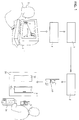
- The system of Figure 1 includes a
computer 2, a vendor's web-site host server 5, a secure site host server 6, a deliverer's web-site host server 8, aremote unlocking device 10 and asecure hatch 12.
Figure 1 illustrates how auser 1 can purchase anitem 14 using the Internet and arrange for it to be securely delivered to the user's house without requiring the user to be present at the time of the delivery. When theuser 1 is viewing the web-site 4 of a vendor and decides to order a product to be delivered to his premises, the user "drags" an icon 3 from the "desktop" of thecomputer 2 and "drops" it onto a designated area of the web-site 4. This action causes the webbrowser software being used to view the web-site 4 to transmit a signal to the vendor's web-site host server 5 via the Internet. The transmitted signal includes the following information:- an identification number identifying thesecure hatch 12 and a code indicating the dimensions of thesecure hatch 12. - Upon receipt of the signal from the
computer 2, the vendor's web-site application running on the vendor's web-site host server 5 examines the code indicating the dimensions of the user's securehatch 12 and uses this information to check whether the requested item is suitable for delivery through the hatch 12 (note that the vendor may have a number of different ways of packaging an item to permit it to be delivered through hatches of different sizes - preferably hatches are built in a small number of standard types - in terms of their dimensions - and vendors can try to ensure that different packaging methods are possible for each or as many as possible of the different standard types of hatch available). - After checking that the requested item can be packaged in such a way as to permit its delivery through the
hatch 12, the vendor's website host server 5 transmits a message to a secure site host server 6. Software running on the secure site host server 6 examines the message to determine the identity ofhatch 12. Having identified thehatch 12, the software looks up the records associated withhatch 12 which it keeps stored in a secure manner. Information included in these records includes the address of thehatch 12 and the identities of remote unlocking devices which are able to unlockhatch 12. Note that prior to installinghatch 12, it has been taught to recognise and to allow itself to be opened by up to fifty different remote unlocking devices, the identities of which are stored by the secure site host server 6. - Note that in the present embodiment only a single delivery company deals with delivering items using the present system. The identity of the or each unlocking device which is in the possession of the delivery company and which is able to unlock the
hatch 12 is then transmitted securely to a server 8 belonging to the delivery company together with address details of thehatch 12. The delivery company uses this information to schedule the picking up of the item to be delivered from the vendor and the delivery of the item to thehatch 12 having identified a suitableremote unlocking device 10, for unlocking thehatch 12. - The delivery company then organises for a delivery person to deliver the item to the correct address of
hatch 12 with theremote unlocking device 10, thehatch 12 is unlocked and theitem 14 is securely delivered throughhatch 12 which is arranged to automatically close and re-lock itself after the item has been delivered through thehatch 12. Thehatch 12 is fitted within theouter perimeter 32a of one of twopanels 32 within adoor 30 leading into the user's property. - Note that when the
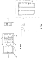
hatch unit 12 is first installed, theuser 1 is invited to visit the secure web-site hosted by server 6 to obtain icon software. The icon software includes the information associated with icon 3 (ie the dimensions of the installedhatch 12 together with the identification number of thehatch 12 by which the server 6 can look up the records associated with hatch 12) together with data enabling thecomputer 2 to generate an appropriate icon on its screen. Note in the present embodiment, 3 types of hatch size are available namely a long thin one with dimensions 270 x 450mm which would accomodate most 4 panel doors; a small square one with dimensions 300 x 300mm which would accomodate most 6 panel and other doors of strange sizes; and a third large one with dimensions 290 x 400mm which would accomodate a case of wine. Each of these types of hatch would have a different icon associated with it. For example, in the present embodiment, the long thin hatch has a red coloured icon, the small type of hatch has a green icon and the large type of hatch has a blue icon. - Figure 2 is a block diagram illustrating the principal components of the locking mechanism associated with
hatch 12. The locking mechanism has three principal components: an electricallyreleasable lock 20, areceiver 22 and apower transformer unit 24. Wires for the electricallyreleasable lock 20 are fastened to thedoor 30 around thepanels 32 between thehinges 54 and the electricallyreleasable lock 20 and from thehinges 54 across to the receiver unit which can be mounted up to 10 metres from thedoor 30 against a corridor wall, etc. - The electrically
releasable lock 20 in the present embodiment comprises a first housing 70 (see figure 3b) having a spring mounted engaging member 71 (see figure 3b) mounted therein and a second housing 72 (see figure 3b) having an electrically releasable engaging surface. The engaging member is biased in a direction out of thefirst housing 70 so as to leave an engaging portion of the engaging member projecting out of the first housing. None-the-less, the engaging portion may be readily urged into the first housing against the biasing force. In operation, the first housing is mounted on one face of a door (hatch door 52 in figure 3b), which is hingedly attached to a frame (frame 50 in figure 3b), flush to the rim of the door opposite to the rim of the door by which the door is hingedly attached to the frame, such that the engaging member projects beyond the rim when in its outwardly biased position. The second housing is attached to the frame such that when the door is in a closed position, the engaging portion is urged by the biasing force to project out of the first housing and into the second housing. The engaging portion of the engaging member has a cam surface operable to co-operate with a corresponding cam surface 73 (see figure 3b) located on the second housing during closing of the door so as to urge the engaging portion into the first housing during closing, thus permitting the door to be fully closed and a flat locking surface which is operable to engage with the electrically releasable engaging surface of the second housing when the door is in its closed position, thus preventing the door from opening in the reverse direction to which it may be closed unless the engaging surface is released. The engaging surface may be released by applying electrical power to the second housing in a manner well known in the art thus permitting the door to be opened. - A suitable device for providing the electrically releasable lock in the present embodiment is a rim-mounted Yale-type lock with a matching 12V dc or ac operated electric release housing. A suitable model of lock and housing for this purpose is a Yale 88 lock together with a DED2000 electric door release produced by Dryad Deedlock and an R0021 Strike housing (rim mounted) also produced by Dryad Deedlock.
- The power transformer is powered by the mains electricity supply and converts this into 12V ac which is used to power both the electrically
releasable lock 20 and the radio receiver 22 (it would have been equally possible to convert the mains power supply into 12V dc for powering either theradio receiver 22 or the electricallyreleasable lock 20, however it is preferable for both thereceiver 22 and thelock 20 to be suitable for being powered by the same transformed power supply be it either dc ac). Suitable power transformers of this type are well known in the art and will not be described here in greater detail. - The
radio receiver 22 is operable to receive radio signals from a remote unlockingdevice 10 and to determine if the signal includes an appropriate unlocking code. If an appropriate unlocking code is detected then thereceiver 22 generates an output voltage signal of 12V ac (ie it passes on the signal produced by the transformer 24). This power signal is then output to the rim-mounted electricdoor release unit 72 which thereby releases thelock 70 permitting thehatch door 52 to be opened. A suitable radio receiver for this purpose is an 008AM receiver produced by R.F.Solutions. Such a receiver includes a memory in which is stored a release code which is compared with the transmitted code as received and which causes the output signal for activating the electric door release to be generated in the event that a predetermined relationship or correspondence between the stored code and the received code is detected. The particular protocol used by the 008AM receiver is known as the KeyLoq algorithm and is well known in the art of wireless telemetry. - Referring now to Figure 3a, the
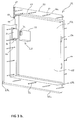
hatch 12 is shown mounted within theouter perimeter 32a of apanel 32 of adoor 30. The panel (of which only theouter perimeter 32a remains after fitting hatch 12) is made of relatively thin wood compared to the main structure of thedoor 30. The hatch includes aframe 50 which is securely attached to theouter perimeter 32a of thepanel 32 and ahatch door 52 which is attached to theframe 50 via a pair of hinges 54. Thehatch door 52 is attached via thehinges 54 so as to permit it to swing inwardly (ie into the property to which thedoor 30 leads). Thehatch door 52 has ahandle 56 mounted on its outward facing edge to permit thehatch door 52 to be pulled closed from an open position. - The
frame 50 of thehatch 12 can be made of galvanised steel or aluminium. This can be electroplated to be silver or brass finished. Thehatch door 52 is made of wood and can be painted to match the existingpanels 32 of thedoor 30. - Figure 3b is an illustrative cut-away perspective view of the
hatch 12 prior to being fitted to thedoor 30, viewed from the inward direction (ie the direction in which thehatch door 52 may swing about the hinges 54-not shown in figure 3b-into an open position). Theframe 50 is formed from fourlengths 66a,66b,68a,68b of metal plate lying flat in the plane of the frame and integrally attached at their ends to form a rectangle. In this embodiment, two of the lengths 68a,68b are approximately 40cm long and two 66a,66b are approximately 29cm long to form a rectangular frame of 40cm by 29cm. Each length is approximately 5cm wide and 6mm thick. Aflange 62 is integrally attached to the fourlengths 66a,66b,68a,68b along their length approximately 1cm radially away from theinside edge 59 of each of the fourlengths 66a,66b,68a,68b and extends inwardly approximately 3cm, perpendicularly away from the plane of the frame. Also integrally attached to the fourlengths 66a,66b,68a,68b are a number of threaded rods (or bolt shafts) 64. The threadedrods 64 are evenly spaced along thelengths 66a,66b,68a,68b approximately 6cm apart and each is attached to the lengths 60 approximately 2cm radially inwardly from theouter edge 61 of each length and approximately 2cm radially outwardly away from theflange 62. The threaded rods extend inwardly approximately 3cm, perpendicularly away from the plane of the frame (ie parallel to the flange 62). - The
hatch door 52 has a thickness of approximately 1.5cm and a length and width such as to fit snugly within theframe 50 so as to locate along its edges against theportion 63 of thelengths 66a,66b,68a,68b extending radially inwardly of theflange 62. Thehatch door 52 is hingedly attached to theframe 50 at the portion of theflange 62 integrally attached to one 68b of the longer lengths 68a,68b (the right-hand side length as viewed in figure 3b) by means ofhinges 54 which attach to thehatch door 52 along its edge facing the flange 62 (along the right-hand side of thehatch door 52 as viewed in figure 3b). Attached to theinward face 65 of thehatch door 52 but on the opposite side to that at which it is hingedly attached (ie the left-hand side as viewed in figure 3b) is thefirst housing 70 of the electricallyreleasable lock 20. Thesecond housing 72 includes fastening means by which it may be fastened to two adjacent threadedrods 64 such that thesecond housing 72 can receive the engagingportion 71 of the engaging member when thehatch door 52 is in the closed position. - In order to fit the
hatch 12, a rectangular hole is cut out of thepanel 32 of thedoor 30. The hole is dimensioned to just permit theflange 62 to pass through the hole. A series of circular holes are also drilled through the remainingouter perimeter 32a of thepanel 32. The holes are dimensioned and located to fit the threadedrods 64. The cutting and drilling of the holes in the correct locations is most easily achieved using a prepared template. - Referring now to figure 3c, the
hatch frame 50 may include a sealinglip 84 extending around the radially outer edge of thepanels 66a,66b,68a,68b along the inwardly facing edges thereof, so as to seal against the outwardly facing surface of theouter perimeter 32a of thedoor panel 32 when thehatch 12 is fitted. To fit thehatch 12, the threadedrods 64 are inserted through thepre-drilled holes 86 within theouter perimeter 32a of thepanel 32, and then secured by means ofwashers 81 and nuts 82. The threadedrods 64 andwashers 81 and nuts 82 in combination with theframe 50 thus form secure and tamperproof panel attachment means. However, it will be apparent that other such panel attachment means could be used to secure the hatch to the perimeter portion of the panel in such a way that the overall strength or security formally provided by the panel is now provided to at least the same extent by the hatch or receiving means. - As shown in Figure 4, the unlocking
device 10 comprises a power supply in the form of abattery cell 90, a keyboard unit 92, ascreen unit 94, amicrocontroller 96, a Personal Identification Number (PIN)memory 98 and atransmitter 100. In operation, a user must input a PIN using the keyboard unit 92, which is compared by themicrocontroller 96 with a PIN stored within thePIN memory 98. In the event of a successful comparison, the microcontroller enables thetransmitter 100 which sends a signal to thereceiver unit 22; as described above, provided the unlockingdevice 10 is recognised by thereceiver unit 22, thereceiver unit 22 causes the electric door release to operate for a predetermined period of time (eg a few seconds) to enable the deliverer to open thehatch door 52 and deliver theitem 14. - A number of variations or embellishments to the above described embodiment are envisaged. For example, the unlocking device can be made more secure by the inclusion of a voice verification chip. An example of a suitable chip for this purpose is the voice verifacation chip marketed by Keyware of Zaventem in Belgium. This chip is a remote voice verification chip in the sense that it stores voice imprints internally within the chip to permit it to perform a comparison in realtime without having to contact a central database. The voice verification chip will act to disable the
transmitter 100 unless a recognised voice print is detected by the voice verification chip (ie the deliverer must speak into a microphone forming part of the unlockingdevice 10 and the chip will compare the resulting voice imprint with one stored internally). - The unlocking
device 10 may also be fitted with a tamper detection unit which permanently disables thetransmitter 100 in the event of any attempt to disassemble the unlockingdevice 10 and use the transmittingdevice 100 independently. - The
receiver 22 may include an alarm which activates a predetermined time (eg 10secs) after initial opening of the hatch door unless the hatch door is properly closed to alert the deliverer that the door has not been properly closed. The alarm may also sound if an attempt is made to force the hatch without correctly using an unlocking device to warn of illicit forced entry attempts. - The locking
unit 20 may include a manual overide system to prevent access even by a recognised unlocking device. For example, thetransformer 24 can be fitted with a switch for disabling the power supply (ie the transformer may be unplugged from the mains) or a simple manual bolt could be fitted. - The hinges 54 may be spring-loaded to render the
hatch door 52 self-closing. Similarly a separate spring system could be fitted to the hatch to render it self-closing. - The icon could have a number of user preferences associated with it which can be used to give further information to the vendor and/or the delivery company; for example, each icon can store details such as whether the
user 1 prefers daytime or night-time deliveries, whether the deliverer should knock before accessing the hatch in case the user is in, etc. - The present disclosure additionally includes the following numbered clauses:-
- i) A system as claimed in any one of the preceding claims wherein the unlocking device includes an authorisation means which prevents an unauthorised person from using an unlocking device to gain unauthorised access to the recipient's premises.
- ii) A system as in clause (i) wherein the authorisation means includes voice verification means for comparing a voice pattern of an operator of the unlocking device with a pre-stored voice pattern of one or more authorised users of the device.
- iii) Receiving means, preferably arranged to be mounted within a door, for receiving an item, said receiving means including locking means associated with said receiving means, and being actuable between a locked state in which access to a recipient's premises, in which the receiving means is mounted, is prevented and an unlocked state in which said receiving means is openable to permit said item to be delivered to the recipient's premises, by means of any one of a plurality of unlocking devices.
-
Claims (10)
- An item receiving system comprising receiving means, preferably arranged to be mounted within a door, for receiving an item, said receiving means including locking means associated with said receiving means, and being actuable between a locked state in which access to the recipient's premises is prevented and an unlocked state in which said receiving means is openable to permit said item to be delivered to the recipient's premises; and a plurality of unlocking devices for causing the lock to be actuated between the locked state and the unlocked state to permit said item to be delivered.
- An item receiving system as claimed in claim 1 wherein the receiving means includes a frame arranged to be mounted within the outer perimeter of a panel within in a building door, said frame having a door part mounted thereto.
- An item receiving system of claim 2 wherein the receiving means is operable to provide a substantially equivalent level of resistance to force before breaking as that provided by, or formally provided by, the panel within the building door in which the receiving means is mounted.
- An item receiving system as claimed in either one of the preceding claims wherein the locking means is remotely actuable by said unlocking devices.
- A system as claimed in any one of the preceding claims further including means for communicating unlocking information to one or more selected unlocking devices.
- A system as claimed in claim 4 wherein the unlocking information takes the form of unlocking codes which change over time and or after each unlocking code has been used to successfully actuate the locking means to the unlocked state so that a particular unlocking device will require a new unlocking code to open the same receiving means on each occasion that it is desired to open the receiving means.
- An unlocking device for actuating a lockable receiving means mounted within a door for receiving an item too large to be posted through a letterbox, between a locked state and an unlocked state.
- A method of transmitting delivery information between a recipient and a delivery company comprising the steps of:-transmitting information from the recipient to a vendor, said information including details about the size of a receiving means through which an item to be delivered may be delivered, and identifying information associated with the receiving means;supplying said identifying information to a delivery company;transmitting said identifying information to a secure database which holds address details of a plurality of receiving means together with their associated identifying information; andlooking up the address details of the receiving means on the basis of the identifying information and transmitting this to the delivery company.
- A method as claimed in claim 8 wherein the address information includes unlocking information to enable the delivery company to open the receiving means.
- A carrier medium carrying processor implementable instructions for carrying out the steps of claim 8 or 9 during implementation of the instructions.
Applications Claiming Priority (2)
| Application Number | Priority Date | Filing Date | Title |
|---|---|---|---|
| GB0025383 | 2000-10-17 | ||
| GB0025383A GB2368096A (en) | 2000-10-17 | 2000-10-17 | Secure item receiving system |
Publications (2)
| Publication Number | Publication Date |
|---|---|
| EP1208780A2 true EP1208780A2 (en) | 2002-05-29 |
| EP1208780A3 EP1208780A3 (en) | 2003-04-02 |
Family
ID=9901416
Family Applications (1)
| Application Number | Title | Priority Date | Filing Date |
|---|---|---|---|
| EP01308820A Withdrawn EP1208780A3 (en) | 2000-10-17 | 2001-10-17 | Item receiving system |
Country Status (2)
| Country | Link |
|---|---|
| EP (1) | EP1208780A3 (en) |
| GB (1) | GB2368096A (en) |
Cited By (2)
| Publication number | Priority date | Publication date | Assignee | Title |
|---|---|---|---|---|
| WO2006086058A1 (en) * | 2005-02-07 | 2006-08-17 | Computerized Security Systems, Inc. | Security system with remote communication |
| CN111818823A (en) * | 2018-03-06 | 2020-10-23 | 丹尼尔·格拉尼亚·多明格斯 | Door for receiving and sending orders |
Citations (5)
| Publication number | Priority date | Publication date | Assignee | Title |
|---|---|---|---|---|
| US1626157A (en) * | 1926-01-20 | 1927-04-26 | Agnes R Rossman | Service door |
| US5774053A (en) * | 1996-05-02 | 1998-06-30 | Porter; David | Storage device for the delivery and pickup of goods |
| US5979750A (en) * | 1996-09-12 | 1999-11-09 | Kindell; Gary J. | Computerized delivery acceptance system |
| DE20006161U1 (en) * | 2000-04-04 | 2000-06-15 | Müller, Wolfgang T., 78315 Radolfzell | Internet-enabled multi-user goods service box system, MS Box for short |
| WO2001027740A1 (en) * | 1999-10-14 | 2001-04-19 | John K Stevens | Improved package delivery system |
Family Cites Families (2)
| Publication number | Priority date | Publication date | Assignee | Title |
|---|---|---|---|---|
| JPH11137407A (en) * | 1997-08-08 | 1999-05-25 | Tokyo Seimitsu Co Ltd | Door-to-door service box |
| GB2331552B (en) * | 1999-01-30 | 1999-10-06 | Robert Delster Jordan | Lockable parcel box |
-
2000
- 2000-10-17 GB GB0025383A patent/GB2368096A/en not_active Withdrawn
-
2001
- 2001-10-17 EP EP01308820A patent/EP1208780A3/en not_active Withdrawn
Patent Citations (5)
| Publication number | Priority date | Publication date | Assignee | Title |
|---|---|---|---|---|
| US1626157A (en) * | 1926-01-20 | 1927-04-26 | Agnes R Rossman | Service door |
| US5774053A (en) * | 1996-05-02 | 1998-06-30 | Porter; David | Storage device for the delivery and pickup of goods |
| US5979750A (en) * | 1996-09-12 | 1999-11-09 | Kindell; Gary J. | Computerized delivery acceptance system |
| WO2001027740A1 (en) * | 1999-10-14 | 2001-04-19 | John K Stevens | Improved package delivery system |
| DE20006161U1 (en) * | 2000-04-04 | 2000-06-15 | Müller, Wolfgang T., 78315 Radolfzell | Internet-enabled multi-user goods service box system, MS Box for short |
Cited By (2)
| Publication number | Priority date | Publication date | Assignee | Title |
|---|---|---|---|---|
| WO2006086058A1 (en) * | 2005-02-07 | 2006-08-17 | Computerized Security Systems, Inc. | Security system with remote communication |
| CN111818823A (en) * | 2018-03-06 | 2020-10-23 | 丹尼尔·格拉尼亚·多明格斯 | Door for receiving and sending orders |
Also Published As
| Publication number | Publication date |
|---|---|
| GB2368096A (en) | 2002-04-24 |
| GB0025383D0 (en) | 2000-11-29 |
| EP1208780A3 (en) | 2003-04-02 |
Similar Documents
| Publication | Publication Date | Title |
|---|---|---|
| US10292519B1 (en) | Secured delivered mail repository | |
| US7236085B1 (en) | Lock with remotely activated lockout feature | |
| US8633799B1 (en) | Lock with remotely activated lockout feature | |
| US20050253715A1 (en) | Smart mailbox | |
| US20020147919A1 (en) | Secured delivery system for unattended receiving and shipping of parcels and letters | |
| US10814833B1 (en) | Anti-theft license plate display and secure storage system | |
| JPH05506322A (en) | security equipment | |
| JP2010534286A (en) | Intelligent lock management system located in ubiquitous | |
| US20050237149A1 (en) | Over-lock for self-storage units | |
| CN206128879U (en) | Intelligence lock and lock anti -theft system thereof | |
| US20240090693A1 (en) | Secured Receptacle for Delivery Packages | |
| US20010027525A1 (en) | Remote access device and system | |
| EP1208780A2 (en) | Item receiving system | |
| AU2004273763A1 (en) | Improvements in and relating to security means | |
| US10726705B2 (en) | Method for controlling door access with improved safety | |
| EP2157889B1 (en) | Mail delivery system | |
| US20220117429A1 (en) | Secure package receptacle with remote unlocking | |
| CN202904778U (en) | Safety protection system | |
| JP2004234400A (en) | Crime prevention system | |
| CN211115452U (en) | Intelligent anti-trailing linkage interlocking safety door control device | |
| CN220748054U (en) | Multifunctional household burglary-resisting door | |
| CN215213157U (en) | Safety anti-theft door | |
| CN205751099U (en) | Burglar alarm | |
| JPH02209578A (en) | Burglary preventing device in building | |
| JPH06215251A (en) | Door locking device for automatic vending machine |
Legal Events
| Date | Code | Title | Description |
|---|---|---|---|
| PUAI | Public reference made under article 153(3) epc to a published international application that has entered the european phase |
Free format text: ORIGINAL CODE: 0009012 |
|
| AK | Designated contracting states |
Kind code of ref document: A2 Designated state(s): AT BE CH CY DE DK ES FI FR GB GR IE IT LI LU MC NL PT SE TR |
|
| AX | Request for extension of the european patent |
Free format text: AL;LT;LV;MK;RO;SI |
|
| PUAL | Search report despatched |
Free format text: ORIGINAL CODE: 0009013 |
|
| AK | Designated contracting states |
Kind code of ref document: A3 Designated state(s): AT BE CH CY DE DK ES FI FR GB GR IE IT LI LU MC NL PT SE TR Designated state(s): AT BE CH CY DE DK ES FI FR GB GR IE IT LI LU MC NL PT SE TR |
|
| AX | Request for extension of the european patent |
Extension state: AL LT LV MK RO SI |
|
| RIC1 | Information provided on ipc code assigned before grant |
Ipc: 7A 47G 29/20 B Ipc: 7A 47G 29/14 A |
|
| AKX | Designation fees paid | ||
| REG | Reference to a national code |
Ref country code: DE Ref legal event code: 8566 |
|
| STAA | Information on the status of an ep patent application or granted ep patent |
Free format text: STATUS: THE APPLICATION IS DEEMED TO BE WITHDRAWN |
|
| 18D | Application deemed to be withdrawn |
Effective date: 20031003 |