EP1208400B1 - Apparat zur verbesserung der optischen eigenschaften von optischen mikroskopen - Google Patents
Apparat zur verbesserung der optischen eigenschaften von optischen mikroskopen Download PDFInfo
- Publication number
- EP1208400B1 EP1208400B1 EP00919074A EP00919074A EP1208400B1 EP 1208400 B1 EP1208400 B1 EP 1208400B1 EP 00919074 A EP00919074 A EP 00919074A EP 00919074 A EP00919074 A EP 00919074A EP 1208400 B1 EP1208400 B1 EP 1208400B1
- Authority
- EP
- European Patent Office
- Prior art keywords
- objective
- optical
- microscope
- image
- image visualizing
- Prior art date
- Legal status (The legal status is an assumption and is not a legal conclusion. Google has not performed a legal analysis and makes no representation as to the accuracy of the status listed.)
- Expired - Lifetime
Links
- 230000003287 optical effect Effects 0.000 title claims abstract description 56
- 230000006872 improvement Effects 0.000 title claims abstract description 6
- 239000000126 substance Substances 0.000 claims description 16
- 239000007787 solid Substances 0.000 claims description 8
- 238000002156 mixing Methods 0.000 claims description 7
- 239000011521 glass Substances 0.000 claims description 4
- 239000004033 plastic Substances 0.000 claims description 4
- 229920003023 plastic Polymers 0.000 claims description 4
- 230000001105 regulatory effect Effects 0.000 claims description 4
- 239000002184 metal Substances 0.000 claims description 3
- 239000010410 layer Substances 0.000 description 17
- 239000000463 material Substances 0.000 description 7
- 230000004075 alteration Effects 0.000 description 5
- 230000015572 biosynthetic process Effects 0.000 description 5
- 238000005755 formation reaction Methods 0.000 description 5
- 239000007788 liquid Substances 0.000 description 5
- 230000004304 visual acuity Effects 0.000 description 5
- 239000002966 varnish Substances 0.000 description 4
- 238000010586 diagram Methods 0.000 description 3
- 238000004519 manufacturing process Methods 0.000 description 3
- 239000002904 solvent Substances 0.000 description 3
- 229920003002 synthetic resin Polymers 0.000 description 3
- 239000000057 synthetic resin Substances 0.000 description 3
- 239000004793 Polystyrene Substances 0.000 description 2
- 239000002131 composite material Substances 0.000 description 2
- 238000001218 confocal laser scanning microscopy Methods 0.000 description 2
- 239000006260 foam Substances 0.000 description 2
- 230000001788 irregular Effects 0.000 description 2
- 239000002245 particle Substances 0.000 description 2
- 229920002223 polystyrene Polymers 0.000 description 2
- 229920002994 synthetic fiber Polymers 0.000 description 2
- 229910000497 Amalgam Inorganic materials 0.000 description 1
- 229920002160 Celluloid Polymers 0.000 description 1
- 229920005372 Plexiglas® Polymers 0.000 description 1
- NIXOWILDQLNWCW-UHFFFAOYSA-N acrylic acid group Chemical group C(C=C)(=O)O NIXOWILDQLNWCW-UHFFFAOYSA-N 0.000 description 1
- 238000004458 analytical method Methods 0.000 description 1
- 230000000721 bacterilogical effect Effects 0.000 description 1
- 210000004556 brain Anatomy 0.000 description 1
- 230000008859 change Effects 0.000 description 1
- 239000003086 colorant Substances 0.000 description 1
- 238000010276 construction Methods 0.000 description 1
- 238000011840 criminal investigation Methods 0.000 description 1
- 230000000694 effects Effects 0.000 description 1
- 230000036541 health Effects 0.000 description 1
- 230000009027 insemination Effects 0.000 description 1
- 230000003993 interaction Effects 0.000 description 1
- 239000004922 lacquer Substances 0.000 description 1
- 244000005700 microbiome Species 0.000 description 1
- 239000000203 mixture Substances 0.000 description 1
- 238000011206 morphological examination Methods 0.000 description 1
- 239000004926 polymethyl methacrylate Substances 0.000 description 1
- 108090000623 proteins and genes Proteins 0.000 description 1
- 239000004065 semiconductor Substances 0.000 description 1
- 239000002356 single layer Substances 0.000 description 1
- 239000002344 surface layer Substances 0.000 description 1
- 238000001356 surgical procedure Methods 0.000 description 1
- 210000002700 urine Anatomy 0.000 description 1
Images


Classifications
-
- G—PHYSICS
- G02—OPTICS
- G02B—OPTICAL ELEMENTS, SYSTEMS OR APPARATUS
- G02B21/00—Microscopes
- G02B21/02—Objectives
- G02B21/04—Objectives involving mirrors
Definitions
- the invention relates to apparatus for the improvement of the optical qualities of optical microscopes, preferably for increasing the magnifying capacity, relative depth sharpness and the resolving power of such microscopes that are also suitable for producing three-dimensional images.
- a further object of this invention is to provide an image-producing device that can be attached to, or built into such apparatus, and can be used also as a part of the apparatus according to the invention.
- Magnifying instruments of various types are indispensable in the technical and scientific spheres of life, e.g. optical microscopes, macroscopes, astronomical telescopes as well as instruments for space research, but photography, film production and film projection can not be undertaken without optical magnifying instruments either.
- the published Hungarian patent application No. 5153/86 relates to an apparatus the purpose of which is to satisfy the demand for improving the quality of known magnifying systems, that is to improve optical qualities of composite magnifying systems, e.g. their relative depth sharpness and resolving power.
- the proposed apparatus consists of primary and secondary objectives and between them an image visualizing plate containing an image visualizing layer between the primary and secondary objectives.
- the image visualizing plate is positioned in the image plane of the primary objective, which coincides with the object plane of the secondary objective, and it is moved and also rotated at this point.
- the image visualizing plate contains particles dissipated in a substance, the refractive index of which particles differs from the refractive index of the substance.
- a matt glass sheet may be used, for example, as an image visualizing plate.
- An object of this invention is to provide an apparatus that also contains a rotating image visualizing plate through which the optical qualities of the various types of magnifying instruments, particularly optical microscopes can be improved, their relative depth of sharpness, magnifying capacity and resolving power can be increased, and by this means also in cases far exceeding the above mentioned magnification range, aberrations, rainbow-effects and other faults can be avoided, thereby faultless images of the required sharpness can be obtained.
- the invention is based on the recognition that if a tertiary microscope objective is inserted between the rotatable image visualizing plate and the secondary microscope objective in an inverse position as compared to the latter, the above-mentioned causes of fuzziness and chromatic aberrations of the image are eliminated, by moving the inserted tertiary objective to-and-fro along the optical axis; or by increasing the length of the light path the sharpness of the image can be regulated and even set as required, if the tertiary objective is held in a fixed position, and a mirror-pair is placed in the light path between the tertiary and secondary objectives, the members of the V-shaped mirrors forming a 90 degree angle with each other and the mirrors being arranged at a distance from and parallel to each other.
- the tertiary objective of the apparatus is in a fixed position and the sharpness of the image is obtained through the movement of the two mirror-pairs placed in the way of the light path between the secondary and tertiary objectives moved in relation to one and other, preferably by the to-and-fro movement of one mirror pair.
- a structure that consists of two parts as described in the following may be suitable for the apparatus according to the invention.
- One part of this device is a rigid transparent sheet, functioning as the image visualizing plate's carrying body for a single layer of transparent image visualizing substance, which is the second part of the device.
- This substance is applied to the carrying body in a liquid, spreadable state, where it sticks/adheres, solidifies, yet remains transparent, though simultaneously or subsequently to its application, small concavations and protrusions and sideways standing formations are created in it, these blend into one another; in other words: the layer is composed of such formations.
- a two component synthetic-resin can be used as the basic material of the image visualizing layer, like the substance called "UVE Rapid", available in the retail trade.
- the object according to the invention was attained by an apparatus for the improvement of optical qualities of optical microscopes, said microscopes comprising an illuminating unit, a condenser lens, a primary microscope objective with an optical axis, and an ocular or a camera; said apparatus being insertable between the primary microscope objective and the ocular or camera, and said apparatus comprising a rotatable image visualizing plate and a secondary objective, whereby said secondary objective is positioned on said optical axis when the apparatus is inserted in the microscope and it has the same orientation as the primary microscope objective.
- This apparatus is characterised in that it comprises a tertiary microscope objective that is arranged between the image visualizing plate and the secondary objective, the tertiary microscope objective being arranged on the same optical axis as the secondary objective and being inversely orientated with respect to the secondary objective.
- the tertiary objective is movable to-and-fro along its optical axis.
- the mirror pairs have a V -pattern in cross-section and are arranged with a variable spacing from each other;
- the mirror-pairs have mirrors forming a 90 degree angle with each other, and enclose a 45 degree angle with a plane extending between the secondary microscope objective and the tertiary microscope objective and which is vertical to the optical axis of the apparatus;
- one mirror pair of the mirror pairs has a fixed position between the secondary objective and the tertiary objective, and the other mirror pair is placed aligned and parallel with the fixed mirror pair and is movable to and from it;
- the outer surface of the mirrors of the fixed mirror pair, and the inner surface of the mirrors of the movable mirror pair is formed as a reflecting surface (sleek).
- the image visualizing plate has a rigid, transparent carrying body and an image visualizing layer formed on the surface of the carrying body, and this image visualizing layer being formed by a substance applied in liquid state to the surface of the carrying body, the substance is transparent in its solidified state on this surface, the free surface of the solidified substance contains concavations and protrusions blending into each other with arcuate (curved) sections.
- the carrying body is preferably formed by a circular disc made of a solid plastic plate with a mass density lower than that of glass, or by a plastic or metal screen plate containing apertures of 0.5-3.0 mm; this carrying body is heat and deformation resistant in the temperature-range of -40 °C and +100 °C and has a thickness of 0.75-0.8 cm.
- the surface of the image visualizing layer covering the carrying body there are 20-50 concavations and protrusions/cm 2 , their average depth and height, respectively is about 10.0-20.0 ⁇ m, preferably between 15.0-18.0 ⁇ m, and the deviation from the average depth/height values is preferably not more than 50%; and the area of projection of configurations appearing and measured under and above a fictitious dividing plane and blending into each other with arcuate (curved) sections is about between 2.0-5.0 mm 2 .
- the image visualizing layer is formed by a two-component synthetic resin or a synthetic foam or polystyrene dissolved in a nitro-solvent or a varnish (lacquer) derivative (nitro-varnish) or by some similar substance applied in liquid form to the surface of the carrying body, and configurations blending into each other are made in the substance in its not yet solidified state, and then the substance is allowed to solidify.
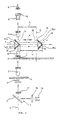
- the illuminating unit 1 of the entire optical microscope system shown in Fig. 1 consists of a lamp 1a, a collector lens 1b, a mirror 2, which projects the light beam emitted by the lamp 1a onto the X optical axis of the system, which is obviously the optical axis of both the optical microscope and the apparatus according to the invention.
- the optical axis X is vertical.
- the primary microscope objective 5 and the secondary objective 7 are positioned identically, but the tertiary objective 16 is placed in an inverse position to these.
- the object carrier 4 When using the system the object carrier 4 is to be inserted between the condenser lens 3 and primary objective 5.
- the user's eye is designated by reference number 9. It may also be observed in Fig. 1 that the vertical geometric rotation axis 10 of the image visualizing plate 6 extends from the optical axis X with eccentricity e , on which the path of the light beam is indicated by arrows.
- the image visualizing plate 6, the tertiary objective 16, the secondary objective 7, as well as the binocular 8 are all parts of the apparatus according to the invention.
- the apparatus also consists of the collector lens 1b, the divided polar filter 17 known in itself, inserted between the mirror 2 and the condenser lens 3, as well as the polar filter 18 mentioned before and positioned on the binocular 8. Due to the interaction of the polar filters arranged according to the above-described pattern and the rotating image visualizing plate 6 described later in detail, three-dimensional images appear in front of the eyes of the person using the apparatus, which was earlier only possible in this field when using very expensive stereo microscopes.
- the object containing the image to be magnified i.e. the object carrier 4 containing a microscopic section is placed between the condenser lens 3 and the primary objective 5, then the lamp 1a of the illuminating unit 1 is switched on.
- the image of the structure on the object carrier 4 will appear in the point of intersection of the optical axis X and of the image-producing device 6.
- the light beam generated by the illuminating unit 1 passes through the condenser lens 3 and is refracted on the structure of the object carrier 4, then the light beam is projected by the primary objective 5 onto the surface of the image visualizing layer of the image visualizing plate 6, shown in Fig. 3; in other words the structure is formed (imaged) here, on this layer.
- the image 11 (Fig 1) is magnified further by the unit consisting of the tertiary objective 16, the secondary objective 7 and the binocular 8.
- the sharpness of the image is regulated by moving the tertiary objective 16 to-and-fro along the optical axis X ; in the position shown in Fig. 1 the tertiary objective 16 is moved in the up and down direction. Due to the use of the tertiary objective 16, even in the case of magnifications exceeding two thousand times images with excellent quality, and images without any aberrations, fuzziness and colour faults are produced.
- the optical system shown in Fig 2 is different from that shown in Fig. 1 only, however, in this case regulation of the depth sharpness does not take place by moving the tertiary objective 16 towards the secondary objective 7 and away from it, but the task is resolved by building two mirror-pairs 14 and 15 into the system, which are arranged at a variable distance f from each other.
- the mirrors 14a, 14b and 15a and 15b of mirror-pairs 14 and 15 are at a 90 degree angle with each other and the mirrors are at a 45 degree angle ⁇ to the plane y , which is vertical to the optical axis X and extends along the median line of the distance between the tertiary objective 16 and the secondary objective 7.
- the mirrors 14a, 14b and 15a, 15b diverge from one another starting from the plane y forming a V pattern as can be seen in Fig. 2.
- the mirror pair 14 is in a fixed position and its outside surface is coated with an amalgam layer 19, and the mirror pair 15 has such a layer on its inner surface.
- the position of the mirror pair 14 is fixed, and the mirror pair 15 can be moved to-and-fro as a single unit, as indicated in Fig. 2 by double arrows k . Due to the above detailed geometrical arrangement the mirrors 14a, 15a, and 14b, 15b are parallel to each other.
- the function (use) of the system shown in Fig. 2 is practically identical with that shown in Fig 1, except the setting of the image sharpness; namely in this case the setting of the sharpness of image 11 magnified further by the tertiary objective 16 is caused by moving the mirror-pairs 15 to-and-fro in the perpendicular direction to the optical axis X as indicated by the double arrows k .
- the path of an elementary ray of light between the tertiary objective 16 and the secondary objective 7 is shown by a dotted line and designated by reference number 20.
- a preferred example of the image visualizing plate 6 containing a carrying body of thickness v 1 and an image visualizing layer 13 of thickness v 2 can be seen in a much larger cross-sectional diagram, which is distorted in order to provide a better overall view.
- the requirements of the carrying body 12 are as follows: heat-resistance and resistance to deformation in the range of temperatures between minus 40 °C and plus 100 °C; its density (specific mass) has to be less than that of glass in order to be easily workable, even if it has a small thickness; it has to be sufficiently be rigid, yet sufficiently flexible.
- a solid, circular disc made of transparent synthetic Plexiglas, or celluloid or acrylic, the diameter D of which can be 35-120 mm, the diameter d of the central aperture 6-40 mm, and the thickness v 1 of the disc 0.75-8.0 mm.
- a screen plate may be used made of synthetic material or metal in which there are apertures the size of which is between 0.1-5.0 mm.
- the material of the image visualizing layer 13 has to be applied in a liquid state to the surface of the carrying body 12. This material becomes solid after its application, yet it remains transparent in its solid state.
- the application of this material is executed in a way as a result of which in the zone of its free surface concavations (indentures) and protrusions blending into one another by curved sections are formed; in other words in general more or less irregular formations - configurations - are produced which are situated lower and higher.
- Fig. 4 the surface structure of the image visualizing layer 13 is shown in a much larger scale than its natural size and the drawing is distorted in order to facilitate a better view.
- the total thickness v2 of the image visualizing layer 13 may be between 0.1-0.5 mm, and the height h of the surface zone containing the formations mentioned before may be between approximately 10.0 and 20.0 ⁇ m, e.g. it can be about 17.0 ⁇ m.
- the surface of the image visualizing layer 13 is designated by the reference letter B .
- the concavations 22 are under a fictitious dividing plane Z extending parallel to the surface 12a of the carrying body 12 and the protrusions 23 are above this fictitious dividing plane Z and appear one after the other (alternately) as irregular configurations blending into each other with arcuate surfaces, and the average depth h 1 of said concavations 22 and height h 2 of said protrusions 23 may equally be 5-10 ⁇ m, but the degree of deviation of the size of certain concavations or/and protrusions from the average value may amount to about 10-50%.
- Such a surface layer zone 13a may be created by using a two-component synthetic resin as the substance of the layer, a material of this kind is available under the commercial name "UVE Rapid”; synthetic foam “HUNGAROCELL”, “NIKECELL” etc. dissolved in nitro-solvent; or polystyrene dissolved in a nitro-solvent; a synthetic varnish (nitro-varnish) etc.
- the apparatus according to the invention provides a unique possibility to examine three dimensional images at extra large magnification with increased relative depth sharpness, far beyond the capacity of a traditional optical microscope.
- This optical system provides further five times magnification in all ranges of the optical microscope. So a one thousand six hundred times magnification, which may be obtained by a hundred times objective and a sixteen times ocular can be increased to a magnification of eight thousand times.
- the apparatus gives a spatial image of the observed object, yet keeps the advantageous characteristics of the traditional optical microscope, such as sharp and crisp contours, contrasts and perfect colours, beside the large magnification.
- the total magnification of the optical system is increased in such a way so that the depth-sharpness does not change.
- the total magnification of an optical microscope fitted with an objective and an ocular with a ten times magnification will be five hundred times, and its depth sharpness 25 microns.
- the total magnification of an optical microscope fitted with an objective and an ocular with a ten times magnification will be five hundred times, and its depth sharpness 25 microns.
- the total magnification will be five hundred times, but the original depth sharpness of 25 microns will remain. But if this five hundred times magnification were attained by using only an optical microscope the depth of sharpness of the image would decrease to about a few microns.
- the system provides spatial images of microorganisms as well, so their behaviour can be studied in their natural environment.
- the system give an experience to the user, as if a Comfocal Laser Scanning Microscope /CLSM/combined with the optical microscope were being used. Information of such a range is obtained, which neither the CLSM, nor an optical microscope is capable of.
- the structure of the image-producing device is exceptionally simple, its production is economic and with its use increased scale of magnifications, spatial images with relatively enhanced depth-sharpness, crisp contours, contrasts and excellent colour qualities are attained.
Landscapes
- Physics & Mathematics (AREA)
- Chemical & Material Sciences (AREA)
- Analytical Chemistry (AREA)
- General Physics & Mathematics (AREA)
- Optics & Photonics (AREA)
- Microscoopes, Condenser (AREA)
- Lenses (AREA)
- Glass Compositions (AREA)
Claims (8)
- Vorrichtung zur Verbesserung der optischen Qualitäten von optischen Mikroskopen, wobei die Mikroskope eine Beleuchtungseinheit (1) eine Kondensorlinse (3) und ein primäres Mikroskopobjektiv (5) mit einer optischen Achse (x) aufweisen, sowie ein Okular oder eine Kamera, sowie eine rotierbare Bildvisualisierungsplatte (6) und ein sekundäres Objektiv (7), wobei das sekundäre Objektiv (7) auf der optischen Achse (x) positioniert ist, wenn der Apparat in das Mikroskop eingesetzt ist und wobei es dieselbe Ausrichtung hat, wie das primäre Objektiv (5) dadurch gekennzeichnet, dass der Apparat ein teritäres Mikroskopobjektiv (16) aufweist, welches zwischen der Bildvisualisierungsplatte (6) und dem sekundären Objektiv (7) angeordnet ist, wobei das teritäre Mikroskopobjektiv (16) auf derselben optischen Achse (x) angeordnet ist, wie das sekundäre Objektiv (7) und hinsichtlich des sekundären Objektivs (7) invers ausgerichtet ist.
- Vorrichtung nach Anspruch 1 dadurch gekennzeichnet, dass das teritäre Mikroskopobjektiv (16) längs der Vorrichtung zur Schärfeeinstellung hin- und herbeweglich ist.
- Vorrichtung nach Anspruch 1 oder 2 gekennzeichnet durch die Anordnung eines geteilten Polfilters (17) zwischen der Kollektorlinse (16) und der Kondensorlinse (3) des optischen Mikroskops und Platzieren des Polfilters (18) auf dem Okular, vorzugsweise auf dem Binokular (8).
- Vorrichtung nach Anspruch 1 bis 3 dadurch gekennzeichnet, dass die Bildvisualisierungsplatte (6) einen festen transparenten Tragkörper (12) und eine feste Bildvisualisierungsschicht (13) aufweist, welche auf der Oberfläche aus einer transparenten Substanz geformt ist, die Vertiefungen (22) und Vorsprünge (23) besitzt, welche mit Bogenabschnitten ineinander übergehen.
- Vorrichtung nach Anspruch 4 dadurch gekennzeichnet, dass der Trägerkörper (12) aus einer vorzugsweise kreisförmigen Scheibe geformt ist, welche aus einer festen Kunststoffplatte mit einer Massendichte niedriger als Glas hergestellt ist.
- Vorrichtung nach Anspruch 4 dadurch gekennzeichnet, dass der Trägerkörper (12) aus einer vorzugsweise kreisrunden Kunststoff- oder Metallschirmplatte mit Öffnungen von 0,5-3,00 mm hergestellt ist.
- Vorrichtung nach Anspruch 5 oder 6 dadurch gekennzeichnet, dass der Trägerkörper (12) in einem Temperaturbereich von - 40° C und 100° hitze- und deformationsresistent ist und eine Dicke von 0,75-0,8 cm besitzt.
- Vorrichtung nach Anspruch 4 bis 7 gekennzeichnet durch 20-50 Vertiefungen (22) und Vorsprünge (23) je cm2 in der Bildvisualisierungsschicht, wobei die Durchschnittstiefe (h2) und -höhe (h2) oberhalb und unterhalb einer fiktiven Teilungsebene (z) etwa 10,0-20,0 µm beträgt, vorzugsweise etwa 15,0-18,0 µm und die Abweichung vom Wert der Durchschnittshöhe/tiefe nicht mehr als 50 % ist und die Projektionsfläche der Vertiefungen (22) und Vorsprünge (23) die bogenförmig ineinander übergehen, welche unterhalb und oberhalb der fiktiven Teilungsebene (z) gemessen ist bei etwa zwischen 2,0-5,0 mm2 liegt.
Applications Claiming Priority (4)
| Application Number | Priority Date | Filing Date | Title |
|---|---|---|---|
| HU9901034 | 1999-04-09 | ||
| HU9901034A HUP9901034A2 (hu) | 1999-04-09 | 1999-04-09 | Készülék nagyítóberendezés, különösen fénymikroszkóp optikai tulajdonságainak a javítására, valamint képmegjelenítő eszköz, különösen ilyen készülékekhez |
| PCT/HU2000/000030 WO2000062113A2 (en) | 1999-04-09 | 2000-04-06 | Apparatus for improvement of the optical qualities of magnifying instruments |
| US10/045,294 US6683715B2 (en) | 1999-04-09 | 2001-10-18 | Apparatus for the improvement of the optical qualities of optical microscopes |
Publications (2)
| Publication Number | Publication Date |
|---|---|
| EP1208400A2 EP1208400A2 (de) | 2002-05-29 |
| EP1208400B1 true EP1208400B1 (de) | 2003-08-27 |
Family
ID=89998062
Family Applications (1)
| Application Number | Title | Priority Date | Filing Date |
|---|---|---|---|
| EP00919074A Expired - Lifetime EP1208400B1 (de) | 1999-04-09 | 2000-04-06 | Apparat zur verbesserung der optischen eigenschaften von optischen mikroskopen |
Country Status (8)
| Country | Link |
|---|---|
| US (1) | US6683715B2 (de) |
| EP (1) | EP1208400B1 (de) |
| AT (1) | ATE248381T1 (de) |
| AU (1) | AU3982500A (de) |
| DE (1) | DE60004868T2 (de) |
| ES (1) | ES2206216T3 (de) |
| HU (1) | HUP9901034A2 (de) |
| WO (1) | WO2000062113A2 (de) |
Families Citing this family (2)
| Publication number | Priority date | Publication date | Assignee | Title |
|---|---|---|---|---|
| HUP9901034A2 (hu) * | 1999-04-09 | 2001-11-28 | Multioptical Kft. | Készülék nagyítóberendezés, különösen fénymikroszkóp optikai tulajdonságainak a javítására, valamint képmegjelenítő eszköz, különösen ilyen készülékekhez |
| CN111710629B (zh) * | 2020-06-23 | 2024-07-09 | 芯米(厦门)半导体设备有限公司 | 一种晶圆对中机构 |
Family Cites Families (13)
| Publication number | Priority date | Publication date | Assignee | Title |
|---|---|---|---|---|
| JP2539491Y2 (ja) * | 1991-10-09 | 1997-06-25 | 惠和商工株式会社 | 光拡散シート材 |
| US3088368A (en) * | 1959-01-15 | 1963-05-07 | Farrand Optical Co Inc | Variable magnification optical system |
| DE3541327A1 (de) * | 1985-11-22 | 1987-05-27 | Schwerionenforsch Gmbh | Streuplatte zum auffangen eines reellen bildes in optischen systemen |
| HUT47333A (en) * | 1986-12-10 | 1989-02-28 | Istvan Stuber | Device for improving resolving power and relative increasing depth of focus of the magnifying systems, favourably microscopes |
| AU612201B2 (en) * | 1987-09-24 | 1991-07-04 | Washington University | Kit for converting a standard microscope into, and design for, a single aperture confocal scanning epi-illumination microscope |
| US5235457A (en) * | 1987-09-24 | 1993-08-10 | Washington University | Kit for converting a standard microscope into a single aperture confocal scanning epi-illumination microscope |
| JPH04304411A (ja) * | 1991-04-01 | 1992-10-27 | Nikon Corp | 高感度顕微鏡 |
| DE4231406A1 (de) * | 1992-09-19 | 1994-03-24 | Leica Mikroskopie & Syst | Hellfeld-Durchlicht-Beleuchtungseinrichtung für Mikroskope |
| US5668660A (en) * | 1994-11-29 | 1997-09-16 | Hunt; Gary D. | Microscope with plural zoom lens assemblies in series |
| US6010747A (en) * | 1996-12-02 | 2000-01-04 | Alliedsignal Inc. | Process for making optical structures for diffusing light |
| JP3416024B2 (ja) * | 1997-05-23 | 2003-06-16 | シャープ株式会社 | 薄膜太陽電池における微粒子塗布膜 |
| US6075643A (en) * | 1997-10-24 | 2000-06-13 | Olympus Optical Co., Ltd. | Reflected fluorescence microscope with multiple laser and excitation light sources |
| HUP9901034A2 (hu) * | 1999-04-09 | 2001-11-28 | Multioptical Kft. | Készülék nagyítóberendezés, különösen fénymikroszkóp optikai tulajdonságainak a javítására, valamint képmegjelenítő eszköz, különösen ilyen készülékekhez |
-
1999
- 1999-04-09 HU HU9901034A patent/HUP9901034A2/hu unknown
-
2000
- 2000-04-06 DE DE60004868T patent/DE60004868T2/de not_active Expired - Fee Related
- 2000-04-06 AU AU39825/00A patent/AU3982500A/en not_active Abandoned
- 2000-04-06 AT AT00919074T patent/ATE248381T1/de not_active IP Right Cessation
- 2000-04-06 EP EP00919074A patent/EP1208400B1/de not_active Expired - Lifetime
- 2000-04-06 ES ES00919074T patent/ES2206216T3/es not_active Expired - Lifetime
- 2000-04-06 WO PCT/HU2000/000030 patent/WO2000062113A2/en not_active Ceased
-
2001
- 2001-10-18 US US10/045,294 patent/US6683715B2/en not_active Expired - Fee Related
Also Published As
| Publication number | Publication date |
|---|---|
| ES2206216T3 (es) | 2004-05-16 |
| HUP9901034A2 (hu) | 2001-11-28 |
| AU3982500A (en) | 2000-11-14 |
| WO2000062113A2 (en) | 2000-10-19 |
| DE60004868T2 (de) | 2004-07-15 |
| WO2000062113A3 (en) | 2001-02-01 |
| ATE248381T1 (de) | 2003-09-15 |
| US6683715B2 (en) | 2004-01-27 |
| DE60004868D1 (de) | 2003-10-02 |
| HU9901034D0 (en) | 1999-06-28 |
| EP1208400A2 (de) | 2002-05-29 |
| US20030076586A1 (en) | 2003-04-24 |
Similar Documents
| Publication | Publication Date | Title |
|---|---|---|
| US6683725B2 (en) | Three dimensional imaging system | |
| Rochow et al. | Introduction to microscopy by means of light, electrons, X rays, or acoustics | |
| US5986811A (en) | Method of and apparatus for generating a 3-D image from a 2-D image having a changeable focusing micro-lens array | |
| US5717453A (en) | Three dimensional imaging system | |
| CN1193389A (zh) | 三维成象系统 | |
| US3442569A (en) | Devices for producing virtual images | |
| Kuo et al. | Fabrication and investigation of the bionic curved visual microlens array films | |
| Yuan et al. | 3D microscope image acquisition method based on zoom objective | |
| EP1208400B1 (de) | Apparat zur verbesserung der optischen eigenschaften von optischen mikroskopen | |
| DE69524195T2 (de) | Weitwinkelobjektivsystem | |
| Murray et al. | Light microscopy | |
| JP2926685B2 (ja) | 拡大装置,特に顕微鏡の焦点深度を相対的に増大し,解像力を向上させる装置 | |
| Kurtz | Orthostereoscopy | |
| BRPI0805205A2 (pt) | aparato de apoio de materias ópticos para auxiliar a visualização, processo para auxiliar a visualização de objetos, material óptico com foco ajustável | |
| SE504419C2 (sv) | Optomekanisk deflektoranordning för linjedisplayer | |
| Christopher et al. | Using 3D printed optical elements for multifocal image scanning microscopy | |
| RU12264U1 (ru) | Зеркально-линзовый объектив | |
| Riddell | On the binocular microscope | |
| Hamly et al. | Electron and optical microscope interpretation of the wall of Pleurosigma angulatum | |
| US5059011A (en) | Apparatus for the relative increase of depth sharpness and improvement of resolving power of magnifying systems, particularly microscopes | |
| JP2006510047A (ja) | 補助レンズ | |
| GB2423828A (en) | Magnifying device with areas of different magnification | |
| CN1204062A (zh) | 远焦变焦透镜系统 | |
| Shepard | Patent Reviews: 3,164,662; 3,170,980; 3,172,941; 3,173,985; 3,190,172; 3,191,490; 3,191,493; 3,227,042; 3,227,041; 3,236,151; 3,237,520; 3,240,120; 3,241,442; 3,241,443; 3,244,073; 3,244,074; 3,246,563; 3,247,764; 3,249,008; 3,249,009 | |
| Radl | Lcd Pupil Expansion For Stereo Viewing |
Legal Events
| Date | Code | Title | Description |
|---|---|---|---|
| PUAI | Public reference made under article 153(3) epc to a published international application that has entered the european phase |
Free format text: ORIGINAL CODE: 0009012 |
|
| 17P | Request for examination filed |
Effective date: 20020219 |
|
| AK | Designated contracting states |
Kind code of ref document: A2 Designated state(s): AT BE CH CY DE DK ES FI FR GB GR IE IT LI LU MC NL PT SE |
|
| RTI1 | Title (correction) |
Free format text: APPARATUS FOR THE IMPROVEMENT OF THE OPTICAL QUALITIES OF OPTICAL MICROSCOPES |
|
| RTI1 | Title (correction) |
Free format text: APPARATUS FOR THE IMPROVEMENT OF THE OPTICAL QUALITIES OF OPTICAL MICROSCOPES |
|
| GRAH | Despatch of communication of intention to grant a patent |
Free format text: ORIGINAL CODE: EPIDOS IGRA |
|
| GRAH | Despatch of communication of intention to grant a patent |
Free format text: ORIGINAL CODE: EPIDOS IGRA |
|
| GRAA | (expected) grant |
Free format text: ORIGINAL CODE: 0009210 |
|
| AK | Designated contracting states |
Designated state(s): AT BE CH CY DE DK ES FI FR GB GR IE IT LI LU MC NL PT SE |
|
| PG25 | Lapsed in a contracting state [announced via postgrant information from national office to epo] |
Ref country code: FI Free format text: LAPSE BECAUSE OF FAILURE TO SUBMIT A TRANSLATION OF THE DESCRIPTION OR TO PAY THE FEE WITHIN THE PRESCRIBED TIME-LIMIT Effective date: 20030827 Ref country code: CY Free format text: LAPSE BECAUSE OF FAILURE TO SUBMIT A TRANSLATION OF THE DESCRIPTION OR TO PAY THE FEE WITHIN THE PRESCRIBED TIME-LIMIT Effective date: 20030827 |
|
| REG | Reference to a national code |
Ref country code: GB Ref legal event code: FG4D |
|
| REG | Reference to a national code |
Ref country code: CH Ref legal event code: EP |
|
| REG | Reference to a national code |
Ref country code: IE Ref legal event code: FG4D |
|
| REF | Corresponds to: |
Ref document number: 60004868 Country of ref document: DE Date of ref document: 20031002 Kind code of ref document: P |
|
| PG25 | Lapsed in a contracting state [announced via postgrant information from national office to epo] |
Ref country code: GR Free format text: LAPSE BECAUSE OF FAILURE TO SUBMIT A TRANSLATION OF THE DESCRIPTION OR TO PAY THE FEE WITHIN THE PRESCRIBED TIME-LIMIT Effective date: 20031127 Ref country code: DK Free format text: LAPSE BECAUSE OF FAILURE TO SUBMIT A TRANSLATION OF THE DESCRIPTION OR TO PAY THE FEE WITHIN THE PRESCRIBED TIME-LIMIT Effective date: 20031127 |
|
| REG | Reference to a national code |
Ref country code: SE Ref legal event code: TRGR |
|
| REG | Reference to a national code |
Ref country code: CH Ref legal event code: NV Representative=s name: BRAUN & PARTNER PATENT-, MARKEN-, RECHTSANWAELTE |
|
| PG25 | Lapsed in a contracting state [announced via postgrant information from national office to epo] |
Ref country code: PT Free format text: LAPSE BECAUSE OF FAILURE TO SUBMIT A TRANSLATION OF THE DESCRIPTION OR TO PAY THE FEE WITHIN THE PRESCRIBED TIME-LIMIT Effective date: 20040127 |
|
| PG25 | Lapsed in a contracting state [announced via postgrant information from national office to epo] |
Ref country code: LU Free format text: LAPSE BECAUSE OF NON-PAYMENT OF DUE FEES Effective date: 20040406 Ref country code: IE Free format text: LAPSE BECAUSE OF NON-PAYMENT OF DUE FEES Effective date: 20040406 |
|
| PG25 | Lapsed in a contracting state [announced via postgrant information from national office to epo] |
Ref country code: MC Free format text: LAPSE BECAUSE OF NON-PAYMENT OF DUE FEES Effective date: 20040430 |
|
| REG | Reference to a national code |
Ref country code: ES Ref legal event code: FG2A Ref document number: 2206216 Country of ref document: ES Kind code of ref document: T3 |
|
| ET | Fr: translation filed | ||
| PLBE | No opposition filed within time limit |
Free format text: ORIGINAL CODE: 0009261 |
|
| STAA | Information on the status of an ep patent application or granted ep patent |
Free format text: STATUS: NO OPPOSITION FILED WITHIN TIME LIMIT |
|
| 26N | No opposition filed |
Effective date: 20040528 |
|
| PGFP | Annual fee paid to national office [announced via postgrant information from national office to epo] |
Ref country code: DE Payment date: 20040930 Year of fee payment: 5 Ref country code: GB Payment date: 20040930 Year of fee payment: 5 |
|
| PGFP | Annual fee paid to national office [announced via postgrant information from national office to epo] |
Ref country code: ES Payment date: 20041001 Year of fee payment: 5 |
|
| PGFP | Annual fee paid to national office [announced via postgrant information from national office to epo] |
Ref country code: NL Payment date: 20041019 Year of fee payment: 5 Ref country code: FR Payment date: 20041019 Year of fee payment: 5 |
|
| PGFP | Annual fee paid to national office [announced via postgrant information from national office to epo] |
Ref country code: BE Payment date: 20041022 Year of fee payment: 5 Ref country code: AT Payment date: 20041022 Year of fee payment: 5 |
|
| PGFP | Annual fee paid to national office [announced via postgrant information from national office to epo] |
Ref country code: SE Payment date: 20041025 Year of fee payment: 5 Ref country code: CH Payment date: 20041025 Year of fee payment: 5 |
|
| REG | Reference to a national code |
Ref country code: IE Ref legal event code: MM4A |
|
| PG25 | Lapsed in a contracting state [announced via postgrant information from national office to epo] |
Ref country code: IT Free format text: LAPSE BECAUSE OF NON-PAYMENT OF DUE FEES Effective date: 20050406 Ref country code: AT Free format text: LAPSE BECAUSE OF NON-PAYMENT OF DUE FEES Effective date: 20050406 |
|
| PG25 | Lapsed in a contracting state [announced via postgrant information from national office to epo] |
Ref country code: SE Free format text: LAPSE BECAUSE OF NON-PAYMENT OF DUE FEES Effective date: 20050407 Ref country code: ES Free format text: LAPSE BECAUSE OF NON-PAYMENT OF DUE FEES Effective date: 20050407 |
|
| PG25 | Lapsed in a contracting state [announced via postgrant information from national office to epo] |
Ref country code: LI Free format text: LAPSE BECAUSE OF NON-PAYMENT OF DUE FEES Effective date: 20050430 Ref country code: CH Free format text: LAPSE BECAUSE OF NON-PAYMENT OF DUE FEES Effective date: 20050430 Ref country code: BE Free format text: LAPSE BECAUSE OF NON-PAYMENT OF DUE FEES Effective date: 20050430 |
|
| BERE | Be: lapsed |
Owner name: *MULTIOPTICAL KFT Effective date: 20050430 |
|
| PG25 | Lapsed in a contracting state [announced via postgrant information from national office to epo] |
Ref country code: NL Free format text: LAPSE BECAUSE OF NON-PAYMENT OF DUE FEES Effective date: 20051101 Ref country code: DE Free format text: LAPSE BECAUSE OF NON-PAYMENT OF DUE FEES Effective date: 20051101 |
|
| EUG | Se: european patent has lapsed | ||
| REG | Reference to a national code |
Ref country code: CH Ref legal event code: PL |
|
| GBPC | Gb: european patent ceased through non-payment of renewal fee |
Effective date: 20050406 |
|
| PG25 | Lapsed in a contracting state [announced via postgrant information from national office to epo] |
Ref country code: FR Free format text: LAPSE BECAUSE OF NON-PAYMENT OF DUE FEES Effective date: 20051230 |
|
| NLV4 | Nl: lapsed or anulled due to non-payment of the annual fee |
Effective date: 20051101 |
|
| REG | Reference to a national code |
Ref country code: FR Ref legal event code: ST Effective date: 20051230 |
|
| REG | Reference to a national code |
Ref country code: ES Ref legal event code: FD2A Effective date: 20050407 |
|
| BERE | Be: lapsed |
Owner name: *MULTIOPTICAL KFT Effective date: 20050430 |