EP1207690A1 - Head-mounted display - Google Patents
Head-mounted display Download PDFInfo
- Publication number
- EP1207690A1 EP1207690A1 EP00951981A EP00951981A EP1207690A1 EP 1207690 A1 EP1207690 A1 EP 1207690A1 EP 00951981 A EP00951981 A EP 00951981A EP 00951981 A EP00951981 A EP 00951981A EP 1207690 A1 EP1207690 A1 EP 1207690A1
- Authority
- EP
- European Patent Office
- Prior art keywords
- frame
- head
- image display
- display device
- members
- Prior art date
- Legal status (The legal status is an assumption and is not a legal conclusion. Google has not performed a legal analysis and makes no representation as to the accuracy of the status listed.)
- Withdrawn
Links
Images





Classifications
-
- H—ELECTRICITY
- H04—ELECTRIC COMMUNICATION TECHNIQUE
- H04N—PICTORIAL COMMUNICATION, e.g. TELEVISION
- H04N9/00—Details of colour television systems
- H04N9/12—Picture reproducers
- H04N9/31—Projection devices for colour picture display, e.g. using electronic spatial light modulators [ESLM]
- H04N9/3141—Constructional details thereof
-
- G—PHYSICS
- G02—OPTICS
- G02B—OPTICAL ELEMENTS, SYSTEMS OR APPARATUS
- G02B27/00—Optical systems or apparatus not provided for by any of the groups G02B1/00 - G02B26/00, G02B30/00
- G02B27/01—Head-up displays
- G02B27/017—Head mounted
- G02B27/0176—Head mounted characterised by mechanical features
-
- H—ELECTRICITY
- H04—ELECTRIC COMMUNICATION TECHNIQUE
- H04N—PICTORIAL COMMUNICATION, e.g. TELEVISION
- H04N5/00—Details of television systems
- H04N5/64—Constructional details of receivers, e.g. cabinets or dust covers
-
- H—ELECTRICITY
- H04—ELECTRIC COMMUNICATION TECHNIQUE
- H04N—PICTORIAL COMMUNICATION, e.g. TELEVISION
- H04N5/00—Details of television systems
- H04N5/74—Projection arrangements for image reproduction, e.g. using eidophor
- H04N5/7475—Constructional details of television projection apparatus
- H04N5/7491—Constructional details of television projection apparatus of head mounted projectors
Definitions
- the present invention relates to a head-mounted display device including an optical system that projects an image, which is produced by a built-in image display means, on the observer's retinas.
- Japanese Patent Unexamined Publication No. 10(1998)-293544 has disclosed a head-mounted image display device that consists mainly of a display casing, right and left supporting frames, a nose rest member, head pressing members, and ear rest members.
- the display casing accommodates LCDs and others.
- the right and left supporting frames are borne by joint members, which are detachably attached to the display casing, so that the right and left supporting frames can pivot on the joint members.
- the nose rest member is fixed to the display casing.
- the head pressing members are attached to the supporting frames so that they can slide.
- the ear rest members are attached to the head pressing members so that they can move together with the head pressing members.
- the head-mounted image display device disclosed in the Japanese Patent Unexamined Publication No. 10(1998)-293544 has its operability improved, there is room for improvement in the structures of the joint members and supporting frames, which are the components of the display device, in terms of their strength and cost. Moreover, there is room for improvement in attaching condition of earphones from the viewpoint of ease of use.
- An object of the present invention is to provide a head-mounted image display device that has components whose structure is simple, whose strength is sufficient, whose capability is satisfactory, and whose cost can be lowered.
- a head-mounted image display device having an image producing unit.
- the image producing unit includes an image display means and a projecting optical system that projects an image, which is produced by the image display means, on the observer's eyes.
- the head-mounted image display device further includes a casing, a pair of frame supporting members, and a pair of frame members.
- the casing accommodates the image producing unit.
- the pair of frame supporting members is fixed to the casing.
- the pair of frame members is worn on the head and supported by the frame supporting members so that the frame members can freely pivot on the frame supporting members.
- an image produced by the image producing unit is projected on the observer's eyes.
- the respective pair to the frame supporting members has the same shape.
- a head-mounted image display device having an image producing unit.
- the image producing unit includes an image display means and a projecting optical system that projects an image, which is produced by the image display means, on the observer's eyes.
- the head-mounted image display device includes a casing, a pair of frame supporting members, and a pair of frame members.
- the casing accommodates the image producing unit.
- the pair of frame supporting members is fixed to the casing.
- the pair of frame members is worn on the head and supported by the frame supporting members so that the frame members can freely pivot on the frame supporting members.
- the each frame member has ribs formed on the surface thereof which faces outside with the head-mounted image display device worn on the head.
- the ribs are extended over an effective range in the longitudinal direction of each frame member.
- the ribs on each frame member are a plurality of ribs formed in the width direction.
- a groove defined with the inner surfaces of the ribs on each frame member serves as a passage groove through which an earphone cord is passed.
- a head-mounted image display device having an image producing unit.
- the image producing unit includes an image display means and a projecting optical system that projects an image, which is produced by the image display means, on the observer's eyes.
- the head-mounted image display device includes a casing body, a pair of frame supporting members, and a pair of frame members.
- the casing accommodates the image producing unit.
- the pair of frame supporting members is fixed to the casing body.
- the pair of frame members is worn on the head and supported by the pair of frame supporting members so that the frame members can pivot on the frame supporting members.
- an image produced by the image producing unit can be projected on the observer's eyes.
- the each frame member has facing pins formed on the inner surfaces of flanges constituting the proximal portion of each frame member that acts as a fulcrum.
- the each frame supporting member has pin supporting hole, into which the pin is fitted, bored therein.
- Fig. 1 is a perspective view showing the appearance of a head-mounted image display device HMD in accordance with an embodiment of the present invention.
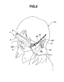
- Fig. 2 is a perspective view showing the head-mounted image display device (HMD) worn on the head.
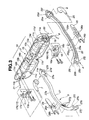
- Fig. 3 is an exploded perspective view showing the major components of the head-mounted image display device HMD.
- An HMD 1 in accordance with the embodiment of the present invention consists mainly of an image producing unit 2, right and left frames 4 and 5, and a controller 8.
- the image producing unit 2 has LCDs, which serves as an image display means, enclosed in covers 11 and 22.
- the right and left frame units 4 and 5 are borne by the cover 11 so that they can pivot, and used to wear the HMD on the head.
- the controller 8 is connected to the image producing unit over a cable 9 over which a control signal and an image signal are transmitted.
- a line linking fulcrums on which right and left frames 25 and 26 that will be described later pivot that is, a line linking the centers of frame supports 16 and 17 that will be described later shall be axis X0.
- An axis that extends vertically while being orthogonal to the axis X0 shall be axis Y0.
- An axis that extends back and forth while being orthogonal to the axis X0 shall be axis Z0.
- a direction parallel to the axis X0 shall be a direction X.
- a direction parallel to the axis Y0 shall be a direction Y.
- a direction parallel to the axis Z0 shall be a direction Z.
- the HMD 1 When the HMD 1 is used to view an image, the HMD 1 is worn on the observer's head 101 with a nose rest 3 mounted on the nose 102 and with right and left frame units 5 and 4 hung on the ears 103.
- the nose rest 3 is formed as part of the cover of the image producing unit 2.
- right and left image producing windows 11d and 11e of the image producing unit 2 are located in front of the observer's eyes.
- the observer mounts an image and sound recording memory card on a card mount 8a of the controller 8.
- a video signal read from the memory card is transferred from the controller 8. Consequently, an image is displayed on the LCDs.
- the light carrying the display image is converged on the observer's eyes through the image producing windows 11d and 11e. Consequently, the image is viewed.
- sounds are heard with right and left earphones 7 and 6 detached from the right and left frame units 5 and 4 and inserted into the ears 103.
- the image producing unit 2 consists mainly of the front and rear covers 22 and 11, an image producing block 10, right and left frame supports 17 and 16, right and left earphone cords 21 and 20, and a signal cable 9.
- the front and rear covers 22 and 11 are casing members.
- the image producing block 10 is borne by the rear cover 11.
- the right and left frame supports 17 and 16 that are paired frame supporting members are also borne by the rear cover 11.
- the right and left earphone cords 21 and 20 are routed to the image producing block 10.
- the signal cable 9 is routed to the image producing block 10 through a connector and held in a bushing 19.
- the earphones 6 and 7 are of a headphone-embedded type.
- the earphone cord 20 is passed through a passage groove 25h formed in the left frame 25 that will be described later.
- the right earphone cord 21 is passed through a passage groove 27h formed in the right frame 27.
- the right or left frame unit 5 or 4 consists mainly of a right or left frame 27 or 25 and the adjuster 28. or 26.
- the right and left frames 27 and 25 are a pair of frame members supported by the right and left frame supports 17 and 16 so that the frame members can pivot freely.
- the adjusters 28 and 26 are a pair of adjusters attached to the frames so that the adjusters can slide freely.
- the adjusters 28 and 26 are magnitude-of-frame pivot changing devices.
- the image producing block 10 is fixed to and borne by the rear cover 11.
- the image producing block 10 includes right and left LED surface light sources 12b and 12a, right and left LCDs 13b and 13a, right and left prisms 14b and 14a, and a circuit board 15.
- the right and left LCDs 13b and 13a serve as an image display means and are located below the surface light sources.
- the right and left prisms 14b and 14a are located below the LCDs.
- An IC serving as a LCD drive circuit for driving the LCDs 13b and 13a and an IC serving as an audio circuit are mounted on the circuit board 15.
- the earphone cords 21 and 20 are routed within the rear cover 11 as mentioned below. Specifically, the earphone cord 21 or 20 is passed through a gap between bosses 11b or 11a to which the frame support 17 or 16 is screwed and which are formed on the wall of the rear cover 11. After the earphone cord 21 or 20 is knotted, the earphone cord 21 or 20 is passed behind the LED surface light source 12b or 12a and then soldered directly to the circuit board 15.
- the right and left frame supports 17 and 16 are formed using the same member, and attached to the right and left ends of the rear cover 11. When attached, the right and left frame supports 17 and 16 are faced.
- Fig. 4 is a perspective view of the frame support 16.
- Fig. 5 is a plan view of the frame support 16.
- Fig. 6 is an A-A sectional view of the frame support 16 shown in Fig. 5, and
- Fig. 7 is a B-B sectional view thereof.
- the frame support 16 has attachment holes 16a, concave parts 16b and 16h, inner walls 16c and 16i, and frame supporting holes 16d and 16j.
- the attachment holes 16a are joined to the bosses 11a formed on the rear cover 11 using screws.
- the concave parts 16b and 16h are formed in the upper and lower surfaces respectively.
- the inner walls 16c and 16i are the walls of the concave parts and contacts frame flanges.
- the frame supporting holes 16d and 16j are bored in the concave parts. Pins formed on the frame 25 and 27, which will be described later, are fitted into the frame supporting holes 16.
- An axis Y1 linking the frame supporting holes 16d and 16j is inclined by an angle + ⁇ 1 (approximately + 8°) relative to the direction Y.
- the angle ⁇ 1 corresponds to an inclination by which the plane on which the left and right frame supported by the frame support 16 pivots is inclined.
- a peripheral convex part 16e for preventing the left frame from coming off is formed on the perimeter of the frame supporting hole 16d in the concave part 16b of the upper surface. Furthermore, a concave part 16f is formed as an L-shaped groove for assisting in insertion or removal of one of the pins formed on the left frame. A step 16g is formed one step below the concave part 16f.
- the same peripheral convex part is formed on the perimeter of the frame supporting hole 16j bored in the concave part 16h in the lower (back) surface of the frame support 16. Furthermore, a concave part serving as an L-shaped groove for assisting in insertion or removal of the other pin formed on the left frame, and a step 16k are also formed.
- the right frame support 17 is, as mentioned above, realized with the same shaped member as the left frame support 16.
- the right frame support 17 is fixed to the right bosses 11b formed on the rear cover 11 in a vertically reversed state relative to the left frame support 16.
- An axis Y2 linking frame supporting holes 17d and 17j bored in the right frame support 17 is inclined by a tilt angle of - ⁇ 1 (approximately - 8°).
- Fig. 3 The appearance of the left frame 25 is shown in Fig. 3 that is the perspective view and in Fig. 14 that is a side view of the left frame 25 with the HMD 1 worn on the head and seen from left.
- Part of the left frame 25 is shown in detail in Fig. 8, Fig. 9, Fig. 10, and Fig. 11.
- Fig. 8 is a perspective view showing the proximal portion of the left frame that acts as a fulcrum.
- Fig. 9 is a plan view showing the distal portion of the left frame.
- Fig. 10 is a C-C sectional view of the distal portion shown in Fig. 9.
- Fig. 11 is a D-D sectional view of the distal portion shown in Fig. 9.
- the shape of the right frame 27 that will be described later is symmetric to the shape of the left frame 25.
- the appearance of the right frame 27 is shown in Fig. 15 that is a side view of the right frame 23 with the HMD 1 worn on the head and seen from right.
- the left frame 25 has, as shown in Fig. 8, two ribs 25a of upper and lower ribs formed on the outer surface thereof, which faces outside with the HMD worn on the head, over substantially the whole range in the longitudinal direction.
- the upper and lower ribs 25a are formed in order to reinforce the frame.
- a groove 25h defined by the ribs 25a has the middle portion thereof covered with the adjuster 26 that will be described later.
- the groove 25h is, as shown in Fig. 11, used as a passage groove through which the earphone cord 20 is passed.
- the right frame 27 has two ribs of upper and lower ribs 27a formed on the outer surface thereof, which faces outside with the HMD worn on the head, along substantially the whole range in the longitudinal direction.
- the upper and lower ribs 27a are formed in order to reinforce the right frame.
- a groove 27h sandwiched by the ribs 27a has the middle portion thereof covered with the adjuster 28 that will be described later.
- the groove 27h is used as a passage groove through which the earphone cord 21 is passed.
- pins 25b and 25c are formed on the inner surfaces of flanges 25i and 25j that constitute the proximal portion of the left frame which act as a fulcrum.
- the pins 25b and 25c are facing and fitted into the frame supporting holes 16d and 16j.
- An axis Y1 linking the pins 25b and 25c is inclined by an angle of + ⁇ 1 relative to the direction Y.
- the direction Y is orthogonal to a major axis plane (a plane containing a center line, which passes the center of the width of the left frame) defined in the proximal portion of the left frame that acts as a fulcrum.
- the distal portion of the left frame 25 that has an opening 25d and acts as an earphone holder is shifted down by a dimension S with respect to the major axis plane P1.
- the major axis plane P1 is defined in the proximal portion thereof that has the pins 25b and 25c and acts as a fulcrum.
- the right frame 27 has, as shown in Fig. 3, pins 27b and 27c formed on the inner surfaces of flanges 27i and 27j that constitute the proximal portion of the right frame 27 which acts as a fulcrum.
- the pins 27b and 27c are facing and fitted into the frame supporting holes 17d and 17j of the frame support 17 so that the right frame 27 can pivot freely.
- An axis Y2 linking the pins 27b and 27c is inclined by an angle - ⁇ relative to the direction Y.
- the direction Y is orthogonal to a major axis plane P2 ((a plane containing a center line that passes the center of the width of the right frame) (see Fig. 15)) defined in the proximal portion of the right frame 27 that acts as a fulcrum.
- the distal portion of the right frame 27 that has an opening 27d and acts as an earphone holder, as shown in Fig. 15, is shifted down by a dimension S with respect to the major axis plane P2.
- the major axis plane P2 is defined in the proximal portion thereof that acts as a fulcrum and that has the pins 26b and 26c.
- the left frame 25 has, as shown in Fig. 3 and Fig. 8, three projections 25g formed near the proximal portion thereof that acts as a fulcrum.
- the adjuster 26 is mounted on the portion of the left frame having the three projections so that the adjuster 26 can slide. Claws 26a of the adjuster 26 are fitted in gaps among the projections 25g, whereby the adjuster 26 is positioned.
- the right frame 27 has, as shown in Fig. 3, three projections 27g formed near the proximal portion thereof that acts as a fulcrum.
- the adjuster 28 is mounted on the portion of the right frame 27 having the projections 27g so that the adjuster 28 can slide. Claws 28a of the adjuster 28 are fitted in gaps among the projections 27g, whereby the adjuster 28 is positioned.
- the adjuster 26 is symmetric in the width direction thereof in which the claws 26a as well as distal projections 26b are formed.
- the distal projections 26b are used to change a magnitude of pivot/open and shaped like prongs of a fork.
- the adjuster 28 has the same shape as the adjuster 26.
- the adjuster 28 has distal projections 28b, which are used to change a magnitude of pivot/open and shaped like prongs of a fork, as well as the claws 28a.
- the distal portion of the left frame 25 has, as shown in Fig. 9 and Fig. 10, the opening 25d and two claws 25e and 25f that are facing, and thus acts as an earphone holder.
- the earphone holder is symmetric in the width direction thereof.
- the earphone 6 When the HMD 1 is carried by a user, the earphone 6 is held in the earphone holder. In this case, the earphone 6 is first engaged with either of the claws 25e and 25f facing each other, and then fitted in the opening 25d so that the earphone will be clamped by the claws 25e and 25f. Referring to Fig. 9, the earphone 6 may be slid below the claws 25e and 25f from above or below in the width direction and then held in the stowage.
- the proximal portion of the right frame 27 has, as shown in Fig. 3, the opening 27d and claws 27e and 27f that are facing, and thus acts as a laterally-symmetric earphone holder.
- the procedure of putting the earphone 7 in the earphone holder is the same as the procedure of putting the earphone 6 in the earphone holder formed in the left frame 25.
- FIG. 12A and Fig. 12B are plan views showing the left frame 25 attached to the left frame support 16.
- Fig. 12A shows a use state (for viewing) in which the left frame 25 is turned in a direction R1 (a direction of opening).
- Fig. 12B shows a folded state (a portable or storable state) in which the left frame 25 is turned in a direction R2 (a direction of closing).
- the pins 25b and 25c of the left frame 25 are fitted into the frame supporting holes 16d and 16j, the pins 25b and 25c are first temporarily engaged with the narrow steps 16g and 16k of the frame support 16 from a direction D1. Thereafter, the space between the pins 25b and 25c is widened, and passed through the concave parts 16f of the frame support that are the L-shaped grooves assisting in insertion or removal of the pins. Finally, the pins 25b and 25c are fitted into the frame supporting holes 16d and 16j.
- the frame supporting holes 16d and 16j are inclined by an angle + ⁇ 1. Therefore, when the left frame 25 is attached to the frame support 16, the axis Y1 linking the pins 25b and 25c of the left frame 25 is also inclined by the angle + ⁇ 1 as shown in Fig. 14. Consequently, when the HMD 1 is worn on the head, the major axis plane P1 defined in the proximal portion of the left frame 25 that acts as a fulcrum is kept horizontal and aligned with the direction Z.
- the procedure of attaching or detaching the right frame 27 to or from the frame support 17 is the same as the procedure of attaching or detaching the left frame 25.
- the frame supporting holes 17d and 17j are inclined by an angle - ⁇ 1. Therefore, when the frame 27 is attached to the frame support 17, the axis Y2 linking the pins 27b and 27c of the frame 27 is inclined by the angle - ⁇ 1 as shown in Fig. 15. Consequently, when the HMD 1 is worn on the head, the major axis plane P2 defined in the proximal portion of the right frame that acts as a fulcrum is kept horizontal and aligned with the direction Z.
- the distal portion of the right or left frame 27 or 25 that acts as the earphone holder is shifted down by the dimension S with respect to the proximal portion thereof that acts as a fulcrum. Therefore, when the HMD 1 is worn on the observer's head 101, the image producing windows 11d formed in the cover of the HMD 1 are disposed opposite the observer's eyes with the portions near the distal portions of the right and left frames placed on the ears 103. An image can therefore be viewed optimally.
- the right and left frames 27 and 25 are pushed outwards by the head and deformed elastically. Compressing force with which the frames compress the head can be adjusted by changing a magnitude (angle) of pivot, by which the right or left frame pivots in the direction of spreading (direction R1) using the adjuster 28 or 26.
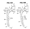
- Fig. 13A and Fig. 13B are plan views showing adjustment of an angle by which the left frame can pivot.
- the adjuster 26 has the claws 26a fitted into a gap between an outer pair of projections 25g formed on the left frame 25.
- the flanges 25i and 25j of the left frame 25 can contact directly the inner walls 16c of the frame support 16.
- the left frame 25 can be widely spread in the direction R1.
- the adjuster 26 is slid towards the proximal portion of the frame that acts as a fulcrum.
- the claws 26a are fitted into a gap between an inner pair of projections 25g of the left frame 25.
- each of the distal projections 26b of the adjuster 26 intervenes between the inner wall 16c of the frame support 16 and the flange 25i or 25j of the left frame 25.
- the left frame 25 can be spread in the direction R1 by a smaller angle.
- the number of projections 27g or 25g of the right or left frame 27 or 25 over which the adjuster 28 or 26 is mounted is three.
- the adjusters 28 and 26 can therefore be slid to either of two positions.
- the present invention is not limited to this mode.
- a click that locks the adjuster at two or more specified positions may be formed in the frames or adjusters.
- a spreading angle can be adjusted finely.
- the adjusters 28 and 26 may not be locked at any specified positions but may be slid to any position.
- the spreading angle can be adjusted to any desired value but need not be set to any of specified values.
- the distal projections 28b and 26b of the adjusters 28 and 26 must be tapered or the inner walls of the frame supports 17 and 16 must be continuously inclined.
- the HMD 1 of the present embodiment having the aforesaid components is used to view an image
- the HMD 1 is, as shown in Fig. 2, worn on the head 101 with the right and left arms 27 and 25 turned in the direction of spreading.
- the nose rest 3 is placed on the nose 102.
- the image producing windows 11e and 11d of the image producing unit 2 are located in front of the observer's eyes.
- the earphones 7 and 6 are taken out of the earphone holders and inserted into the ears 103.
- the earphones 7 and 6 are stowed in the earphone holders so that the earphone cords will not sag.
- the right and left frames 27 and 25 are folded so that the HMD 1 can be carried or stowed readily.
- Fig. 16 shows the HMD 1 in a portable or storable state, wherein the HMD 1 is seen from behind.
- the right and left frames 27 and 25 are folded inwards.
- the axis Y1 linking the pins 25b and 15c of the left frame 25 is inclined back and forth by an angle + ⁇ 1
- the axis linking the pins 27b and 27c of the right frame 27 is inclined back and forth by an angle - ⁇ 1. Therefore, when the frames are folded as shown in Fig. 16, the right and left frames 27 and 25 will not interfere with each other.
- the HMD 1 may be worn on a user who has a big nose or a different skull. In this case, if the HMD 1 is used as it is, the nose rest 3 moves obliquely forwards. The distal portions (that are near the earphone holders) of the right and left frames 27 and 25 are therefore located in the middles of the ears. The user wearing the HMD would feel uncomfortable.
- the right and left frames 27 and 25 of the HMD 1 are detached temporarily, replaced with each other, and then attached to the frame supports 17 and 16. This results in a custom-made HMD. Using this custom-made HMD, even a user who has a big nose can enjoy an image viewing optimally.
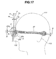
- Fig. 17 is a side view showing a custom-made HMD worn on the head 111 of an observer who has a big nose, wherein the HMD is seen from left.
- the nose rest 3 is lifted because of the big nose 112. Therefore, the direction Y and direction Z (consistent with the direction of the major axis plane P2) defined on the custom-made HMD are deflected from the vertical direction V and horizontal direction H respectively by an angle - ⁇ 0.
- the axis Y3 linking the pins 27b and 27c of the right frame 27 attached to the left frame support is inclined by another angle of - ⁇ 1.
- the distal portion of the right frame 27 attached to the left frame support 16 is, unlike the one shown in Fig. 14, shifted up by the dimension S.
- the distal portion will therefore not be located in the middle of the ear but will be placed at the upper normal position on the ear 113.
- the left frame 25 is attached to the right frame support 17 in the same manner, and therefore placed at the upper normal position on the ear 113. Consequently, as long as the custom-made HMD having the frames replaced with each other is employed, even an observer having a big nose can view an image normally.
- the HMD 1 of the present embodiment has advantages described below.
- a head-mounted image display device that is compact and easily worn on the head.
- Right and left components of the HMD can be realized using a common member and formed strong enough. Earphones are easy to use.
- the user-friendly and low-cost HMD is provided.
Landscapes
- Engineering & Computer Science (AREA)
- Multimedia (AREA)
- Signal Processing (AREA)
- Physics & Mathematics (AREA)
- General Physics & Mathematics (AREA)
- Optics & Photonics (AREA)
- Liquid Crystal (AREA)
Abstract
A head-mounted image display device consists mainly of
an image producing unit (2), right and left frames (27 and
25), and a controller (8). The image producing unit has
image display LCDs enclosed with covers (11 and 12). The
right and left frames useful in wearing the head-mounted
image display device HMD on the head are supported by frame
supports (17 and 16) that are fixed to the cover (11).
Herein, the right and left frames are detachably attached to
the frame supports. An earphone cord (21 or 20) is guided
along ribs which are formed on the outer surface of the
right or left frame. An earphone (7 or 6) is detachably
attached to an earphone holder formed in the distal or rear
portion of the right or left frame. Thus, there is provided
a head-mounted image display device that is compact, that
can be readily worn on the head, and that not only enables
viewing of a display screen image but also simplifies
observation of an ambient environment.
Description
The present invention relates to a head-mounted display
device including an optical system that projects an image,
which is produced by a built-in image display means, on the
observer's retinas.
Various types of head-mounted image display devices
have been proposed as compact display devices that are worn
on the head and display an image directly viewable with the
eyes.
For example, Japanese Patent Unexamined Publication No.
10(1998)-293544 has disclosed a head-mounted image display
device that consists mainly of a display casing, right and
left supporting frames, a nose rest member, head pressing
members, and ear rest members. The display casing
accommodates LCDs and others. The right and left supporting
frames are borne by joint members, which are detachably
attached to the display casing, so that the right and left
supporting frames can pivot on the joint members. The nose
rest member is fixed to the display casing. The head
pressing members are attached to the supporting frames so
that they can slide. The ear rest members are attached to
the head pressing members so that they can move together
with the head pressing members. The operability of the
head-mounted image display device for activating various
kinds of features has improved.
However, although the head-mounted image display device
disclosed in the Japanese Patent Unexamined Publication No.
10(1998)-293544 has its operability improved, there is room
for improvement in the structures of the joint members and
supporting frames, which are the components of the display
device, in terms of their strength and cost. Moreover,
there is room for improvement in attaching condition of
earphones from the viewpoint of ease of use.
The present invention attempts to overcome the
foregoing drawbacks. An object of the present invention is
to provide a head-mounted image display device that has
components whose structure is simple, whose strength is
sufficient, whose capability is satisfactory, and whose cost
can be lowered.
According to one aspect of the present invention, there
is provided a head-mounted image display device having an
image producing unit. The image producing unit includes an
image display means and a projecting optical system that
projects an image, which is produced by the image display
means, on the observer's eyes. The head-mounted image
display device further includes a casing, a pair of frame
supporting members, and a pair of frame members. The casing
accommodates the image producing unit. The pair of frame
supporting members is fixed to the casing. The pair of
frame members is worn on the head and supported by the frame
supporting members so that the frame members can freely
pivot on the frame supporting members. When the casing is
worn on the head using the frame members, an image produced
by the image producing unit is projected on the observer's
eyes. The respective pair to the frame supporting members
has the same shape.
According to another aspect of the present invention,
there is provided a head-mounted image display device having
an image producing unit. The image producing unit includes
an image display means and a projecting optical system that
projects an image, which is produced by the image display
means, on the observer's eyes. The head-mounted image
display device includes a casing, a pair of frame supporting
members, and a pair of frame members. The casing
accommodates the image producing unit. The pair of frame
supporting members is fixed to the casing. The pair of
frame members is worn on the head and supported by the frame
supporting members so that the frame members can freely
pivot on the frame supporting members. When the casing is
worn on the head using the frame members, an image produced
by the image producing unit is projected on the observer's
eyes. The each frame member has ribs formed on the surface
thereof which faces outside with the head-mounted image
display device worn on the head. The ribs are extended over
an effective range in the longitudinal direction of each
frame member. The ribs on each frame member are a plurality
of ribs formed in the width direction. A groove defined
with the inner surfaces of the ribs on each frame member
serves as a passage groove through which an earphone cord is
passed.
According to still another aspect of the present
invention, there is provided a head-mounted image display
device having an image producing unit. The image producing
unit includes an image display means and a projecting
optical system that projects an image, which is produced by
the image display means, on the observer's eyes. The head-mounted
image display device includes a casing body, a pair
of frame supporting members, and a pair of frame members.
The casing accommodates the image producing unit. The pair
of frame supporting members is fixed to the casing body.
The pair of frame members is worn on the head and supported
by the pair of frame supporting members so that the frame
members can pivot on the frame supporting members. When the
casing body is worn on the head using the frame members, an
image produced by the image producing unit can be projected
on the observer's eyes. The each frame member has facing
pins formed on the inner surfaces of flanges constituting
the proximal portion of each frame member that acts as a
fulcrum. The each frame supporting member has pin
supporting hole, into which the pin is fitted, bored therein.
An embodiment of the present invention will be
described in conjunction with the drawings below.
Fig. 1 is a perspective view showing the appearance of
a head-mounted image display device HMD in accordance with
an embodiment of the present invention. Fig. 2 is a
perspective view showing the head-mounted image display
device (HMD) worn on the head. Fig. 3 is an exploded
perspective view showing the major components of the head-mounted
image display device HMD.
An HMD 1 in accordance with the embodiment of the
present invention consists mainly of an image producing unit
2, right and left frames 4 and 5, and a controller 8. The
image producing unit 2 has LCDs, which serves as an image
display means, enclosed in covers 11 and 22. The right and
left frame units 4 and 5 are borne by the cover 11 so that
they can pivot, and used to wear the HMD on the head. The
controller 8 is connected to the image producing unit over a
cable 9 over which a control signal and an image signal are
transmitted.
Hereinafter, a description will proceed on the
assumption that a leftward direction is the left side
relative to an observer who sees the front and rear covers
22 and 11 of the image producing unit 2, and that a
rightward direction is the right side relative to the
observer. Moreover, a line linking fulcrums on which right
and left frames 25 and 26 that will be described later pivot,
that is, a line linking the centers of frame supports 16 and
17 that will be described later shall be axis X0. An axis
that extends vertically while being orthogonal to the axis
X0 shall be axis Y0. An axis that extends back and forth
while being orthogonal to the axis X0 shall be axis Z0.
Moreover, a direction parallel to the axis X0 shall be a
direction X. A direction parallel to the axis Y0 shall be a
direction Y. A direction parallel to the axis Z0 shall be a
direction Z. When an upper point in the direction Y tilts
forward and a lower point therein tilts backward, an
inclination shall be + . When the upper point in the
direction Y tilts backward and the lower point therein tilts
forward, the inclination shall be - .
When the HMD 1 is used to view an image, the HMD 1 is
worn on the observer's head 101 with a nose rest 3 mounted
on the nose 102 and with right and left frame units 5 and 4
hung on the ears 103. The nose rest 3 is formed as part of
the cover of the image producing unit 2. In this state,
right and left image producing windows 11d and 11e of the
image producing unit 2 are located in front of the
observer's eyes. The observer mounts an image and sound
recording memory card on a card mount 8a of the controller 8.
A video signal read from the memory card is transferred from
the controller 8. Consequently, an image is displayed on
the LCDs. The light carrying the display image is converged
on the observer's eyes through the image producing windows
11d and 11e. Consequently, the image is viewed. Moreover,
sounds are heard with right and left earphones 7 and 6
detached from the right and left frame units 5 and 4 and
inserted into the ears 103.
The structures of the components of the HMD 1 will be
described below.
The image producing unit 2 consists mainly of the front
and rear covers 22 and 11, an image producing block 10,
right and left frame supports 17 and 16, right and left
earphone cords 21 and 20, and a signal cable 9. The front
and rear covers 22 and 11 are casing members. The image
producing block 10 is borne by the rear cover 11. The right
and left frame supports 17 and 16 that are paired frame
supporting members are also borne by the rear cover 11. The
right and left earphone cords 21 and 20 are routed to the
image producing block 10. The signal cable 9 is routed to
the image producing block 10 through a connector and held in
a bushing 19.
The earphones 6 and 7 are of a headphone-embedded type.
The earphone cord 20 is passed through a passage groove 25h
formed in the left frame 25 that will be described later. A
portion of the earphone code 20 coming out of an adjuster 26,
which will be described later, includes a stretchable and
contractile coil spring portion (curled portion) 20a (see
Fig. 1). Likewise, the right earphone cord 21 is passed
through a passage groove 27h formed in the right frame 27.
A portion of the right earphone cord 21 coming out of an
adjuster 28, which will be described later, includes a
similar stretchable and contractile coil spring portion
(curled portion).
The right or left frame unit 5 or 4 consists mainly of
a right or left frame 27 or 25 and the adjuster 28. or 26.
The right and left frames 27 and 25 are a pair of frame
members supported by the right and left frame supports 17
and 16 so that the frame members can pivot freely. The
adjusters 28 and 26 are a pair of adjusters attached to the
frames so that the adjusters can slide freely. The
adjusters 28 and 26 are magnitude-of-frame pivot changing
devices.
The image producing block 10 is fixed to and borne by
the rear cover 11. The image producing block 10 includes
right and left LED surface light sources 12b and 12a, right
and left LCDs 13b and 13a, right and left prisms 14b and 14a,
and a circuit board 15. The right and left LCDs 13b and 13a
serve as an image display means and are located below the
surface light sources. The right and left prisms 14b and
14a are located below the LCDs. An IC serving as a LCD
drive circuit for driving the LCDs 13b and 13a and an IC
serving as an audio circuit are mounted on the circuit board
15.
In the image producing block 10, light rays carrying
images transmitted by the LCDs 13b and 13a are reflected
from the prisms 14b and 14a, and projected on the observer's
eyes through the image producing windows 11e and 11d.
The earphone cords 21 and 20 are routed within the rear
cover 11 as mentioned below. Specifically, the earphone
cord 21 or 20 is passed through a gap between bosses 11b or
11a to which the frame support 17 or 16 is screwed and which
are formed on the wall of the rear cover 11. After the
earphone cord 21 or 20 is knotted, the earphone cord 21 or
20 is passed behind the LED surface light source 12b or 12a
and then soldered directly to the circuit board 15.
The right and left frame supports 17 and 16 are formed
using the same member, and attached to the right and left
ends of the rear cover 11. When attached, the right and
left frame supports 17 and 16 are faced.
Fig. 4 is a perspective view of the frame support 16.
Fig. 5 is a plan view of the frame support 16. Fig. 6 is an
A-A sectional view of the frame support 16 shown in Fig. 5,
and Fig. 7 is a B-B sectional view thereof.
The frame support 16 has attachment holes 16a, concave
parts 16b and 16h, inner walls 16c and 16i, and frame
supporting holes 16d and 16j. The attachment holes 16a are
joined to the bosses 11a formed on the rear cover 11 using
screws. The concave parts 16b and 16h are formed in the
upper and lower surfaces respectively. The inner walls 16c
and 16i are the walls of the concave parts and contacts
frame flanges. The frame supporting holes 16d and 16j are
bored in the concave parts. Pins formed on the frame 25 and
27, which will be described later, are fitted into the frame
supporting holes 16. An axis Y1 linking the frame
supporting holes 16d and 16j is inclined by an angle +1
(approximately + 8°) relative to the direction Y. The angle
1 corresponds to an inclination by which the plane on which
the left and right frame supported by the frame support 16
pivots is inclined.
Moreover, a peripheral convex part 16e for preventing
the left frame from coming off is formed on the perimeter of
the frame supporting hole 16d in the concave part 16b of the
upper surface. Furthermore, a concave part 16f is formed as
an L-shaped groove for assisting in insertion or removal of
one of the pins formed on the left frame. A step 16g is
formed one step below the concave part 16f.
On the other hand, the same peripheral convex part is
formed on the perimeter of the frame supporting hole 16j
bored in the concave part 16h in the lower (back) surface of
the frame support 16. Furthermore, a concave part serving
as an L-shaped groove for assisting in insertion or removal
of the other pin formed on the left frame, and a step 16k
are also formed.
On the other hand, the right frame support 17 is, as
mentioned above, realized with the same shaped member as the
left frame support 16. The right frame support 17 is fixed
to the right bosses 11b formed on the rear cover 11 in a
vertically reversed state relative to the left frame support
16. An axis Y2 linking frame supporting holes 17d and 17j
bored in the right frame support 17 is inclined by a tilt
angle of - 1 (approximately - 8°).
The appearance of the left frame 25 is shown in Fig. 3
that is the perspective view and in Fig. 14 that is a side
view of the left frame 25 with the HMD 1 worn on the head
and seen from left. Part of the left frame 25 is shown in
detail in Fig. 8, Fig. 9, Fig. 10, and Fig. 11. Fig. 8 is a
perspective view showing the proximal portion of the left
frame that acts as a fulcrum. Fig. 9 is a plan view showing
the distal portion of the left frame. Fig. 10 is a C-C
sectional view of the distal portion shown in Fig. 9. Fig.
11 is a D-D sectional view of the distal portion shown in
Fig. 9.
The shape of the right frame 27 that will be described
later is symmetric to the shape of the left frame 25. The
appearance of the right frame 27 is shown in Fig. 15 that is
a side view of the right frame 23 with the HMD 1 worn on the
head and seen from right.
The left frame 25 has, as shown in Fig. 8, two ribs 25a
of upper and lower ribs formed on the outer surface thereof,
which faces outside with the HMD worn on the head, over
substantially the whole range in the longitudinal direction.
The upper and lower ribs 25a are formed in order to
reinforce the frame. A groove 25h defined by the ribs 25a
has the middle portion thereof covered with the adjuster 26
that will be described later. The groove 25h is, as shown
in Fig. 11, used as a passage groove through which the
earphone cord 20 is passed.
On the other hand, the right frame 27 has two ribs of
upper and lower ribs 27a formed on the outer surface thereof,
which faces outside with the HMD worn on the head, along
substantially the whole range in the longitudinal direction.
The upper and lower ribs 27a are formed in order to
reinforce the right frame. A groove 27h sandwiched by the
ribs 27a has the middle portion thereof covered with the
adjuster 28 that will be described later. The groove 27h is
used as a passage groove through which the earphone cord 21
is passed.
In the left frame 25, pins 25b and 25c are formed on
the inner surfaces of flanges 25i and 25j that constitute
the proximal portion of the left frame which act as a
fulcrum. The pins 25b and 25c are facing and fitted into
the frame supporting holes 16d and 16j. An axis Y1 linking
the pins 25b and 25c is inclined by an angle of + 1
relative to the direction Y. The direction Y is orthogonal
to a major axis plane (a plane containing a center line,
which passes the center of the width of the left frame)
defined in the proximal portion of the left frame that acts
as a fulcrum.
Moreover, the distal portion of the left frame 25 that
has an opening 25d and acts as an earphone holder is shifted
down by a dimension S with respect to the major axis plane
P1. The major axis plane P1 is defined in the proximal
portion thereof that has the pins 25b and 25c and acts as a
fulcrum.
On the other hand, the right frame 27 has, as shown in
Fig. 3, pins 27b and 27c formed on the inner surfaces of
flanges 27i and 27j that constitute the proximal portion of
the right frame 27 which acts as a fulcrum. The pins 27b
and 27c are facing and fitted into the frame supporting
holes 17d and 17j of the frame support 17 so that the right
frame 27 can pivot freely. An axis Y2 linking the pins 27b
and 27c is inclined by an angle - relative to the
direction Y. The direction Y is orthogonal to a major axis
plane P2 ((a plane containing a center line that passes the
center of the width of the right frame) (see Fig. 15))
defined in the proximal portion of the right frame 27 that
acts as a fulcrum.
Furthermore, the distal portion of the right frame 27
that has an opening 27d and acts as an earphone holder, as
shown in Fig. 15, is shifted down by a dimension S with
respect to the major axis plane P2. The major axis plane P2
is defined in the proximal portion thereof that acts as a
fulcrum and that has the pins 26b and 26c. When the HMD 1
is worn on the head as shown in Fig. 14 and Fig. 15, the
direction Y and the direction Z shall be substantially
consistent with a vertical direction and a horizontal
direction respectively.
The left frame 25 has, as shown in Fig. 3 and Fig. 8,
three projections 25g formed near the proximal portion
thereof that acts as a fulcrum. The adjuster 26 is mounted
on the portion of the left frame having the three
projections so that the adjuster 26 can slide. Claws 26a of
the adjuster 26 are fitted in gaps among the projections 25g,
whereby the adjuster 26 is positioned.
On the other hand, the right frame 27 has, as shown in
Fig. 3, three projections 27g formed near the proximal
portion thereof that acts as a fulcrum. The adjuster 28 is
mounted on the portion of the right frame 27 having the
projections 27g so that the adjuster 28 can slide. Claws
28a of the adjuster 28 are fitted in gaps among the
projections 27g, whereby the adjuster 28 is positioned.
The adjuster 26 is symmetric in the width direction
thereof in which the claws 26a as well as distal projections
26b are formed. The distal projections 26b are used to
change a magnitude of pivot/open and shaped like prongs of a
fork. The adjuster 28 has the same shape as the adjuster 26.
Similarly to the adjuster 26, the adjuster 28 has distal
projections 28b, which are used to change a magnitude of
pivot/open and shaped like prongs of a fork, as well as the
claws 28a.
Furthermore, the distal portion of the left frame 25
has, as shown in Fig. 9 and Fig. 10, the opening 25d and two
claws 25e and 25f that are facing, and thus acts as an
earphone holder. The earphone holder is symmetric in the
width direction thereof.
When the HMD 1 is carried by a user, the earphone 6 is
held in the earphone holder. In this case, the earphone 6
is first engaged with either of the claws 25e and 25f facing
each other, and then fitted in the opening 25d so that the
earphone will be clamped by the claws 25e and 25f.
Referring to Fig. 9, the earphone 6 may be slid below the
claws 25e and 25f from above or below in the width direction
and then held in the stowage.
On the other hand, the proximal portion of the right
frame 27 has, as shown in Fig. 3, the opening 27d and claws
27e and 27f that are facing, and thus acts as a laterally-symmetric
earphone holder. The procedure of putting the
earphone 7 in the earphone holder is the same as the
procedure of putting the earphone 6 in the earphone holder
formed in the left frame 25.
Next, the procedure of attaching or detaching the left
frame 25 to or from the frame support 16 will be described
below. Fig. 12A and Fig. 12B are plan views showing the
left frame 25 attached to the left frame support 16. Fig.
12A shows a use state (for viewing) in which the left frame
25 is turned in a direction R1 (a direction of opening).
Fig. 12B shows a folded state (a portable or storable state)
in which the left frame 25 is turned in a direction R2 (a
direction of closing).
In the state shown in Fig. 12A or Fig. 12B, the upper
and lower pins 25b and 25c of the left frame 25 are fitted
into the frame supporting holes 16d and 16j. In the state
shown in Fig. 12A, the flanges 25i and 25j of the left frame
25 contacts the inner walls 16c of the frame support 16.
The left frame 25 does not therefore move inwards (towards
the center of the rear cover 11). Consequently, the upper
and lower pins 25b and 25c will not come off from the frame
supporting holes 16d and 16j.
In the state shown in Fig. 12B, there is a gap between
the flanges 25i and 25j of the left frame 25 and the inner
walls 16c of the frame support 16. Therefore, the left fame
25 can move inwards (towards the center of the rear cover
11). Consequently, while the flanges 25i and 25j of the
left frame 25 are deformed elastically in the thickness
direction thereof, the upper and lower pins 25b and 25c can
be removed from the frame supporting holes 16d and 16j in
order to disassemble the left frame and image producing unit.
Otherwise, the upper and lower pins 25b and 25c can be
inserted into the frame supporting holes 16d and 16j in
order to assemble the left frame and image producing unit.
During the assembling, when the pins 25b and 25c of the
left frame 25 are fitted into the frame supporting holes 16d
and 16j, the pins 25b and 25c are first temporarily engaged
with the narrow steps 16g and 16k of the frame support 16
from a direction D1. Thereafter, the space between the pins
25b and 25c is widened, and passed through the concave parts
16f of the frame support that are the L-shaped grooves
assisting in insertion or removal of the pins. Finally, the
pins 25b and 25c are fitted into the frame supporting holes
16d and 16j.
As mentioned above, the frame supporting holes 16d and
16j are inclined by an angle + 1. Therefore, when the left
frame 25 is attached to the frame support 16, the axis Y1
linking the pins 25b and 25c of the left frame 25 is also
inclined by the angle + 1 as shown in Fig. 14.
Consequently, when the HMD 1 is worn on the head, the major
axis plane P1 defined in the proximal portion of the left
frame 25 that acts as a fulcrum is kept horizontal and
aligned with the direction Z.
On the other hand, the procedure of attaching or
detaching the right frame 27 to or from the frame support 17
is the same as the procedure of attaching or detaching the
left frame 25. However, as mentioned above, the frame
supporting holes 17d and 17j are inclined by an angle - 1.
Therefore, when the frame 27 is attached to the frame
support 17, the axis Y2 linking the pins 27b and 27c of the
frame 27 is inclined by the angle - 1 as shown in Fig. 15.
Consequently, when the HMD 1 is worn on the head, the major
axis plane P2 defined in the proximal portion of the right
frame that acts as a fulcrum is kept horizontal and aligned
with the direction Z.
The distal portion of the right or left frame 27 or 25
that acts as the earphone holder is shifted down by the
dimension S with respect to the proximal portion thereof
that acts as a fulcrum. Therefore, when the HMD 1 is worn
on the observer's head 101, the image producing windows 11d
formed in the cover of the HMD 1 are disposed opposite the
observer's eyes with the portions near the distal portions
of the right and left frames placed on the ears 103. An
image can therefore be viewed optimally.
With the HMD 1 worn on the head, the right and left
frames 27 and 25 are pushed outwards by the head and
deformed elastically. Compressing force with which the
frames compress the head can be adjusted by changing a
magnitude (angle) of pivot, by which the right or left frame
pivots in the direction of spreading (direction R1) using
the adjuster 28 or 26.
The procedure of adjusting the magnitude of pivot
(spreading) by which the right or left frame 27 or 25 pivots
to spread is the same between the right and left frames 27
and 25. The procedure of adjusting the magnitude of pivot
by which the left frame 25 pivots will therefore be
described below.
Fig. 13A and Fig. 13B are plan views showing adjustment
of an angle by which the left frame can pivot. Referring to
Fig. 13A, the adjuster 26 has the claws 26a fitted into a
gap between an outer pair of projections 25g formed on the
left frame 25. The flanges 25i and 25j of the left frame 25
can contact directly the inner walls 16c of the frame
support 16. The left frame 25 can be widely spread in the
direction R1.
In contrast, referring to Fig. 13B, the adjuster 26 is
slid towards the proximal portion of the frame that acts as
a fulcrum. The claws 26a are fitted into a gap between an
inner pair of projections 25g of the left frame 25. In this
state, each of the distal projections 26b of the adjuster 26
intervenes between the inner wall 16c of the frame support
16 and the flange 25i or 25j of the left frame 25. The left
frame 25 can be spread in the direction R1 by a smaller
angle.
The aforesaid adjustment of a spreading angle is
performed on the right frame 27 too. Thus, the manner in
which the right and left frames 27 and 25 are worn on the
head 101, that is, force by which the right and left frames
27 and 25 compress the head 101 can be adjusted.
According to the present embodiment, the number of
projections 27g or 25g of the right or left frame 27 or 25
over which the adjuster 28 or 26 is mounted is three. The
adjusters 28 and 26 can therefore be slid to either of two
positions. The present invention is not limited to this
mode. Alternatively, a click that locks the adjuster at two
or more specified positions may be formed in the frames or
adjusters. In this case, a spreading angle can be adjusted
finely. Moreover, the adjusters 28 and 26 may not be locked
at any specified positions but may be slid to any position.
In this case, the spreading angle can be adjusted to any
desired value but need not be set to any of specified values.
However, in this case, the distal projections 28b and 26b of
the adjusters 28 and 26 must be tapered or the inner walls
of the frame supports 17 and 16 must be continuously
inclined.
When the HMD 1 of the present embodiment having the
aforesaid components is used to view an image, first, the
HMD 1 is, as shown in Fig. 2, worn on the head 101 with the
right and left arms 27 and 25 turned in the direction of
spreading. At this time, the nose rest 3 is placed on the
nose 102. In this state, the image producing windows 11e
and 11d of the image producing unit 2 are located in front
of the observer's eyes. The earphones 7 and 6 are taken out
of the earphone holders and inserted into the ears 103.
With the HMD 1 worn on the head, light representing an
image produced according to a video signal sent from the
controller 8 is projected on the observer's eyes by way of
the prisms 14b and 14a and image producing windows lie and
11d Consequently, an image is viewed. Moreover, sounds
generated according to an audio signal are heard through the
earphones 7 and 6.
Moreover, when the HMD 1 is carried or stowed, the
earphones 7 and 6 are stowed in the earphone holders so that
the earphone cords will not sag. The right and left frames
27 and 25 are folded so that the HMD 1 can be carried or
stowed readily.
Fig. 16 shows the HMD 1 in a portable or storable state,
wherein the HMD 1 is seen from behind. The right and left
frames 27 and 25 are folded inwards. The axis Y1 linking
the pins 25b and 15c of the left frame 25 is inclined back
and forth by an angle + 1, and the axis linking the pins
27b and 27c of the right frame 27 is inclined back and forth
by an angle - 1. Therefore, when the frames are folded as
shown in Fig. 16, the right and left frames 27 and 25 will
not interfere with each other.
The HMD 1 may be worn on a user who has a big nose or a
different skull. In this case, if the HMD 1 is used as it
is, the nose rest 3 moves obliquely forwards. The distal
portions (that are near the earphone holders) of the right
and left frames 27 and 25 are therefore located in the
middles of the ears. The user wearing the HMD would feel
uncomfortable.
According to the present embodiment, the right and left
frames 27 and 25 of the HMD 1 are detached temporarily,
replaced with each other, and then attached to the frame
supports 17 and 16. This results in a custom-made HMD.
Using this custom-made HMD, even a user who has a big nose
can enjoy an image viewing optimally.
Fig. 17 is a side view showing a custom-made HMD worn
on the head 111 of an observer who has a big nose, wherein
the HMD is seen from left. In the worn state shown in Fig.
17, compared with the worn state shown in Fig. 14, the nose
rest 3 is lifted because of the big nose 112. Therefore,
the direction Y and direction Z (consistent with the
direction of the major axis plane P2) defined on the custom-made
HMD are deflected from the vertical direction V and
horizontal direction H respectively by an angle - 0.
Moreover, since the right and left frames are replaced with
each other, the axis Y3 linking the pins 27b and 27c of the
right frame 27 attached to the left frame support is
inclined by another angle of - 1.
The distal portion of the right frame 27 attached to
the left frame support 16 is, unlike the one shown in Fig.
14, shifted up by the dimension S. The distal portion will
therefore not be located in the middle of the ear but will
be placed at the upper normal position on the ear 113. The
left frame 25 is attached to the right frame support 17 in
the same manner, and therefore placed at the upper normal
position on the ear 113. Consequently, as long as the
custom-made HMD having the frames replaced with each other
is employed, even an observer having a big nose can view an
image normally.
The HMD 1 of the present embodiment has advantages
described below.
As mentioned above, according to the present invention,
there is provided a head-mounted image display device (HMD)
that is compact and easily worn on the head. Right and left
components of the HMD can be realized using a common member
and formed strong enough. Earphones are easy to use. Thus,
the user-friendly and low-cost HMD is provided.
Claims (16)
- A head-mounted image display device having an image producing unit (2) which includes an image display means (13a and 13b) and a projecting optical system (12a, 12b, 14a, and 14b) for projecting an image, which is produced by said image display means, on the observer's eyes, said head-mounted image display device comprising:wherein said respective pair to the frame supporting members has the same shape.a casing body (11 and 22) in which said image producing unit is incorporated;a pair of frame supporting members (16 and 17) fixed to said casing body; anda pair of frame members (25 and 27) that is members useful in wearing the head-mounted image display device on the head, and is supported by said frame supporting members so that the frame members can pivot freely;
- A head-mounted image display device having an image producing unit (2) which includes an image display means (13a and 13b) and a projecting optical system (12a, 12b, 14a, and 14b) for projecting an image, which is produced by said image display means, on the observer's eyes, said head-mounted image display device HMD comprising:wherein said frame member has ribs (27a or 25a) formed on the outer surface thereof which faces outside with said head-mounted image display device worn on the head, said ribs being extended over an effective range in the longitudinal direction of the frame member.a casing body (11 and 22) in which said image producing unit is incorporated;a pair of frame supporting members (16 and 17) fixed to said casing body; anda pair of frame members (25 and 27) that is members useful in wearing said head-mounted image display device HMD on the head, and is supported by said frame supporting members so that the frame members can pivot freely,
- The head-mounted image display device HMD according to Claim 2, wherein:said ribs on each frame member are a plurality of ribs lined in the width direction of the frame member; anda groove defined with the inner surfaces of said ribs serves as a passage groove for an earphone cord (20 or 21).
- A head-mounted image display device having an image producing unit (2) which includes an image display means (13a and 13b) and an image projecting optical system (12a, 12b, 14a, and 14b) for projecting an image, which is produced by said image display means, on the observer's eyes, said head-mounted image display device comprising:wherein said frame member has facing pins (25b and 25c or 27b and 27c) formed on the inner surfaces of flanges constituting the proximal portion thereof that acts as a fulcrum; anda casing body (11 and 22) in which said image producing unit is incorporated;a pair of frame supporting members (16 and 17) fixed to said casing body; anda pair of frame members (25 and 27) that is members useful in wearing said head-mounted image display device HMD on the head, and is supported by said pair of frame supporting members so that the frame members can pivot freely,
said frame supporting member has pin supporting holes (16d and 16j or 17d and 17j), into which said pins are fitted, bored therein. - The head-mounted image display device HMD according to Claim 4, wherein an axis (Y1 or Y2) linking said facing pins formed on each frame member is inclined by a predetermined angle relative to a major axis plane defined in the frame member.
- The head-mounted image display device according to Claim 4, wherein said frame member can be attached to or detached from said frame supporting member by elastically deforming said flanges.
- The head-mounted image display device according to Claim 6, wherein:an L-shaped groove (16f or 16g) is formed in one direction along each of said pin supporting holes formed in said frame support member; andsaid frame member is moved along said L-shaped grooves and then attached or detached.
- The head-mounted image display device according to Claim 6, wherein said frame member is attached to or detached from said frame supporting member while being folded substantially into a portable or storable state.
- A head-mounted image display device having an image producing unit (2) which includes an image display means (13a and 13b) and a projecting optical system (12a, 12b, 14a, and 14b) for projecting an image, which is produced by said image display means, on the observer's eyes, said head-mounted image display device comprising:wherein said frame spreading magnitude changing devices is moved relative to said frame member so that the device will have distal projections thereof inserted into or withdrawn from gaps between the contacting portions of said frame supporting member and the contacting portions (25i and 25j or 27i and 27j) of said frame member, whereby a pivot angle by which said frame member can pivot is adjusted at least in two steps.a casing body (11 and 22) in which said image producing unit is incorporated;a pair of frame supporting members (16 and 17) fixed to said casing body;a pair of frame members (25 and 27) that is members useful in wearing said head-mounted image display device on the head, and is supported by said pair of frame supporting members so that the frame members can pivot freely;frame spreading magnitude changing devices (26 and 28) each of which is attached to said frame member so that the device can move relative to said frame member, and is used to adjust an angle of pivot by which the frame member pivots,
- A head-mounted image display device having an image producing unit (2) which includes an image display means (13a and 13b) and a projecting optical system (12a, 12b, 14a, and 14b) for projecting an image, which is produced by said image display means, on the observer's eyes, said head-mounted image display device comprising:wherein said frame spreading magnitude changing devices is moved relative to said frame member so that the device will have distal projections thereof inserted into or withdrawn from gaps between the contacting portions of said frame supporting member and the contacting portions (25i and 25j or 27i and 27j) of said frame member, whereby the pivot angle by which said frame member can pivot is adjusted to be any position that is not a stepwise specified position.a casing body (11 and 22) in which said image producing unit is incorporated;a pair of frame supporting members (16 and 17) fixed to said casing body;a pair of frame members (25 and 27) that is members useful in wearing said head-mounted image display device HMD on the head, and is supported by said pair of frame supporting members so that the frame members can pivot freely; andframe spreading magnitude changing devices (26 and 28) each of which is attached to said frame member so that the device can move relative to said frame member, and is used to adjust a pivot angle by which the frame member can pivot,
- The head-mounted image display device HMD according to Claim 9 or 10, wherein said frame spreading magnitude changing devices are realized with a pair of members, and respective said pair to the members is the same shape.
- The head-mounted image display device HMD according to Claim 9 or 10, wherein:said frame member has a plurality of ribs (25a or 27a) lined in the width direction on an outer surface thereof that faces outside with said head-mounted image display device worn on the head, and said plurality of ribs are extended over an effective range in the longitudinal direction of the frame member;said frame spreading magnitude changing device is attached to cover said ribs; anda groove defined with said ribs and having a portion thereof covered by the frame spreading magnitude changing device is used as an earphone cord passage groove.
- A head-mounted image display device having an image producing unit (2) which includes an image display means (13a and 13b) and a projecting optical system (12a, 12b, 14a, and 14b) for projecting an image, which is produced by said image display means, on the observer's eyes, said head-mounted image display device comprising:wherein earphone holders (25d, 25e, and 25f or 27d, 27e, and 27f) are formed in the distal portion of said frame member.a casing body (11 and 22) in which said image producing unit is incorporated;a pair of frame supporting members (16 and 17) fixed to said casing body; anda pair of frame members (25 and 27) that is members useful in wearing said head-mounted image display device HMD on the head, and is supported by said frame supporting members so that the frame members can pivot freely,
- The head-mounted image display device HMD according to Claim 13, wherein:said earphone holder includes an opening, to which the speaker surface of said earphone is faced, and claws that clamp the body of said earphone, that are faced to each other in the horizontal direction, and that can deform elastically.
- A head-mounted image display device having an image producing unit (2) which includes an image display means (13a and 13b) and a projecting optical system (12a, 12b, 14a, and 14b)for projecting an image, which is produced by said image display means, on the observer's eyes, said head-mounted image display device comprising:wherein said frame member has a distal portion thereof shifted down by a predetermined dimension with respect to a major axis plane (P1) defined in the proximal portion of said frame member that acts as a fulcrum.a casing body (11 and 22) in which said image producing unit is incorporated;a pair of frame supporting members (16 and 17) fixed to said casing body; anda pair of frame members (25 and 27) that is members useful in wearing said head-mounted image display device HMD on the head, and is supported by said frame supporting members so that the frame members can pivot freely,
- The head-mounted image display device HMD according to Claim 15, wherein said paired frame members or said paired frame supporting members can be replaced with each other.
Applications Claiming Priority (3)
| Application Number | Priority Date | Filing Date | Title |
|---|---|---|---|
| JP24006299 | 1999-08-26 | ||
| JP24006299A JP2001069428A (en) | 1999-08-26 | 1999-08-26 | Head mounted display |
| PCT/JP2000/005437 WO2001017239A1 (en) | 1999-08-26 | 2000-08-14 | Head-mounted display |
Publications (2)
| Publication Number | Publication Date |
|---|---|
| EP1207690A1 true EP1207690A1 (en) | 2002-05-22 |
| EP1207690A4 EP1207690A4 (en) | 2010-03-10 |
Family
ID=17053928
Family Applications (1)
| Application Number | Title | Priority Date | Filing Date |
|---|---|---|---|
| EP00951981A Withdrawn EP1207690A4 (en) | 1999-08-26 | 2000-08-14 | Head-mounted display |
Country Status (4)
| Country | Link |
|---|---|
| US (1) | US6762885B1 (en) |
| EP (1) | EP1207690A4 (en) |
| JP (1) | JP2001069428A (en) |
| WO (1) | WO2001017239A1 (en) |
Cited By (3)
| Publication number | Priority date | Publication date | Assignee | Title |
|---|---|---|---|---|
| CN103591414A (en) * | 2013-10-30 | 2014-02-19 | 青岛歌尔声学科技有限公司 | Sliding device and head-mounted display |
| FR3049721A1 (en) * | 2016-04-01 | 2017-10-06 | Thales Sa | ELASTIC BAND HEAD VISUALIZATION SYSTEM FOR AN AIRCRAFT COMPATIBLE WITH AN AUDIO HELMET |
| CN110679142A (en) * | 2017-05-31 | 2020-01-10 | 索尼互动娱乐股份有限公司 | Head-mounted display |
Families Citing this family (39)
| Publication number | Priority date | Publication date | Assignee | Title |
|---|---|---|---|---|
| US7158096B1 (en) * | 1999-06-21 | 2007-01-02 | The Microoptical Corporation | Compact, head-mountable display device with suspended eyepiece assembly |
| USD531998S1 (en) * | 2003-12-31 | 2006-11-14 | Eyeneo Sas | Video display control unit |
| USD523005S1 (en) * | 2003-12-31 | 2006-06-13 | Eyeneo Sas | Video display control unit comprising charging base and control unit box |
| USD513031S1 (en) * | 2004-01-07 | 2005-12-20 | Icuiti Corporation | Virtual display eyeglasses |
| USD556815S1 (en) * | 2004-11-29 | 2007-12-04 | Icuiti Corporation | Virtual display eyeglasses |
| USD521493S1 (en) * | 2005-01-21 | 2006-05-23 | Koninklikjke Philips Electronics, N.V. | Gaming headphone |
| US20070064311A1 (en) * | 2005-08-05 | 2007-03-22 | Park Brian V | Head mounted projector display for flat and immersive media |
| AU2007205168B2 (en) * | 2006-01-06 | 2013-01-31 | Marcio Marc Aurelio Martins Abreu | Biologically fit wearable electronics apparatus and methods |
| USD567768S1 (en) * | 2006-12-20 | 2008-04-29 | Samsung Electronics Co., Ltd. | HMD (head mounted display) |
| JP5190070B2 (en) | 2007-01-12 | 2013-04-24 | コピン コーポレーション | Monocular display device |
| US9217868B2 (en) | 2007-01-12 | 2015-12-22 | Kopin Corporation | Monocular display device |
| USD566738S1 (en) * | 2007-03-09 | 2008-04-15 | Tristram Himmele | Binocular |
| JP4958599B2 (en) * | 2007-03-29 | 2012-06-20 | キヤノン株式会社 | Head-mounted video display device |
| USD579014S1 (en) | 2007-04-03 | 2008-10-21 | Vuxiz Corporation | Personal video display device |
| USD602064S1 (en) * | 2007-05-11 | 2009-10-13 | Konica Minolta Holdings, Inc. | Data display |
| USD591326S1 (en) * | 2008-04-11 | 2009-04-28 | Vuzix Corporation | Personal video display device |
| USD621805S1 (en) | 2009-01-07 | 2010-08-17 | Vuzix Corporation | Personal video display device |
| US8004769B2 (en) * | 2009-03-05 | 2011-08-23 | Nabes, Llc | Binocular apparatus and system |
| JP5170144B2 (en) * | 2010-03-29 | 2013-03-27 | ブラザー工業株式会社 | Glasses-type image display device |
| WO2011137034A1 (en) | 2010-04-27 | 2011-11-03 | Kopin Corporation | Wearable electronic display |
| USD736771S1 (en) | 2010-04-27 | 2015-08-18 | Kopin Corporation | Wearable electronic display |
| USD703634S1 (en) * | 2013-01-10 | 2014-04-29 | Iriver Limited | Bluetooth headset |
| JP2014174366A (en) * | 2013-03-11 | 2014-09-22 | Seiko Epson Corp | Virtual image display device |
| JP6337465B2 (en) * | 2013-12-26 | 2018-06-06 | セイコーエプソン株式会社 | Virtual image display device |
| USD743935S1 (en) * | 2014-11-05 | 2015-11-24 | Stryker European Holdings, I, Llc | Headset |
| JP6536019B2 (en) * | 2014-11-21 | 2019-07-03 | セイコーエプソン株式会社 | Controller and image display system |
| CN105182533B (en) * | 2015-08-28 | 2018-04-06 | 青岛歌尔声学科技有限公司 | Head-mounted display |
| CN107615134B (en) * | 2015-10-23 | 2020-03-24 | 深圳市柔宇科技有限公司 | head mounted display |
| JP1564085S (en) * | 2016-02-19 | 2016-11-28 | ||
| US10459236B2 (en) * | 2016-12-09 | 2019-10-29 | Lg Electronics Inc. | Head-mounted display device with earbud holder |
| CN106940480A (en) * | 2017-05-19 | 2017-07-11 | 陈格为 | A kind of VR glasses earphone accommodating apparatus |
| US10045449B1 (en) * | 2017-06-29 | 2018-08-07 | Oculus Vr, Llc | Adjustable facial-interface systems for head-mounted displays |
| US10895751B1 (en) | 2017-06-29 | 2021-01-19 | Facebook Technologies, Llc | Adjustable facial-interface systems for head-mounted displays |
| US10496130B1 (en) | 2017-07-18 | 2019-12-03 | Facebook Technologies, Llc | Adjustable facial-interface systems for head-mounted displays |
| US10061352B1 (en) * | 2017-08-14 | 2018-08-28 | Oculus Vr, Llc | Distributed augmented reality system |
| JP1674399S (en) * | 2019-01-09 | 2020-12-07 | ||
| KR102808965B1 (en) * | 2019-08-09 | 2025-05-20 | 엘지전자 주식회사 | Electronic device |
| CN113933994A (en) * | 2020-07-14 | 2022-01-14 | 宁波舜宇光电信息有限公司 | AR device |
| USD1121708S1 (en) | 2023-11-15 | 2026-04-07 | Vuzix Corporation | Smart glasses |
Family Cites Families (8)
| Publication number | Priority date | Publication date | Assignee | Title |
|---|---|---|---|---|
| JPS449987Y1 (en) * | 1967-06-13 | 1969-04-22 | ||
| JPS5611050Y2 (en) * | 1977-09-07 | 1981-03-12 | ||
| US5181051A (en) * | 1991-01-17 | 1993-01-19 | Daniel R. Townsend | Magnetic removable display for eyeglasses |
| US6424321B1 (en) * | 1993-10-22 | 2002-07-23 | Kopin Corporation | Head-mounted matrix display |
| CA2174510A1 (en) * | 1993-10-22 | 1995-04-27 | John C. C. Fan | Head-mounted display system |
| JPH0868972A (en) * | 1994-08-29 | 1996-03-12 | Ishiyama Gankyo Kk | Hinge structure of glasses |
| JPH10293544A (en) * | 1997-04-18 | 1998-11-04 | Olympus Optical Co Ltd | Head mounted video display |
| JPH11352904A (en) * | 1998-04-10 | 1999-12-24 | Olympus Optical Co Ltd | Head mounted video display |
-
1999
- 1999-08-26 JP JP24006299A patent/JP2001069428A/en active Pending
-
2000
- 2000-08-14 US US10/031,376 patent/US6762885B1/en not_active Expired - Fee Related
- 2000-08-14 WO PCT/JP2000/005437 patent/WO2001017239A1/en not_active Ceased
- 2000-08-14 EP EP00951981A patent/EP1207690A4/en not_active Withdrawn
Cited By (7)
| Publication number | Priority date | Publication date | Assignee | Title |
|---|---|---|---|---|
| CN103591414A (en) * | 2013-10-30 | 2014-02-19 | 青岛歌尔声学科技有限公司 | Sliding device and head-mounted display |
| CN103591414B (en) * | 2013-10-30 | 2016-01-20 | 青岛歌尔声学科技有限公司 | A kind of sliding device and head display |
| FR3049721A1 (en) * | 2016-04-01 | 2017-10-06 | Thales Sa | ELASTIC BAND HEAD VISUALIZATION SYSTEM FOR AN AIRCRAFT COMPATIBLE WITH AN AUDIO HELMET |
| CN110679142A (en) * | 2017-05-31 | 2020-01-10 | 索尼互动娱乐股份有限公司 | Head-mounted display |
| EP3633978A4 (en) * | 2017-05-31 | 2021-01-13 | Sony Interactive Entertainment Inc. | HEADPHONES |
| CN110679142B (en) * | 2017-05-31 | 2022-05-10 | 索尼互动娱乐股份有限公司 | head mounted display |
| US11619821B2 (en) | 2017-05-31 | 2023-04-04 | Sony Interactive Entertainment Inc. | Head-mounted display |
Also Published As
| Publication number | Publication date |
|---|---|
| WO2001017239A1 (en) | 2001-03-08 |
| US6762885B1 (en) | 2004-07-13 |
| JP2001069428A (en) | 2001-03-16 |
| EP1207690A4 (en) | 2010-03-10 |
Similar Documents
| Publication | Publication Date | Title |
|---|---|---|
| US6762885B1 (en) | Head-mounted display | |
| JP5389493B2 (en) | Glasses-mounted image display device | |
| JP4327364B2 (en) | Articulated nose bridge for head mounted display | |
| JP4440878B2 (en) | Image display device | |
| EP0592318B1 (en) | Head-mounted image display apparatus | |
| JP4887907B2 (en) | Video display device | |
| US20040113867A1 (en) | Head-mountable display system | |
| CN104094592B (en) | Head-mount type display unit, glasses display device and display device eyeglass leg | |
| JP6513573B2 (en) | Spectacles with concealed and invisible optics | |
| US20110090135A1 (en) | Interchangeable display device for a head-mounted display system | |
| US20050174651A1 (en) | Binocular viewing system | |
| JP2001522064A (en) | Lightweight, compact, re-wearable electronic display device for eyeglasses or other head-mounted eyewear | |
| US20050168824A1 (en) | Binocular virtual display imaging device | |
| JP2017147520A (en) | Head mounted type image display device | |
| JPH10197825A (en) | Head-mounted display | |
| WO2022183752A1 (en) | Ar glasses | |
| JP2001154637A (en) | Head mounted display | |
| JPH10294983A (en) | Head mounted video display | |
| US20050146487A1 (en) | Binocular virtual display imaging device | |
| JPH10293544A (en) | Head mounted video display | |
| CN100544414C (en) | Wearable display unit, headset and system incorporating them | |
| JP2002072130A (en) | Head-mounted information display device | |
| JP4973423B2 (en) | Head-mounted image display device | |
| JP2001069427A (en) | Head mounted display device | |
| JPH10333078A (en) | Head-mounted display device |
Legal Events
| Date | Code | Title | Description |
|---|---|---|---|
| PUAI | Public reference made under article 153(3) epc to a published international application that has entered the european phase |
Free format text: ORIGINAL CODE: 0009012 |
|
| 17P | Request for examination filed |
Effective date: 20020109 |
|
| AX | Request for extension of the european patent |
Free format text: AL;LT;LV;MK;RO;SI |
|
| RBV | Designated contracting states (corrected) |
Designated state(s): DE FR GB |
|
| A4 | Supplementary search report drawn up and despatched |
Effective date: 20100208 |
|
| RAP1 | Party data changed (applicant data changed or rights of an application transferred) |
Owner name: OLYMPUS CORPORATION |
|
| 17Q | First examination report despatched |
Effective date: 20100520 |
|
| STAA | Information on the status of an ep patent application or granted ep patent |
Free format text: STATUS: THE APPLICATION IS DEEMED TO BE WITHDRAWN |
|
| 18D | Application deemed to be withdrawn |
Effective date: 20101201 |