BACKGROUND OF THE INVENTION
1. Field of the Invention
This invention relates to a display object generation
method in information processing equipment, a program to
execute and control the same, and a recording medium for
storing the program.
2. Description of the Related Art
Among game programs which are executed by computer game
equipment as information processing equipment, there are
numerous game programs which can execute competitive games
between display objects manipulated by the game player, and
display objects manipulated by a plurality of opposing game
players or controlled by the program.
In some of the competitive games executed by these game
programs, the game player would select one display object
from among a plurality of display objects, and in the course
of the game would modify parameters which define the
characteristics of the display object. Thus through multiple
executions of the game, it would be possible to derive
pleasure by cultivating the display object manipulated by
the game player.
However, the above plurality of display objects are
prepared in advance as display object data, and prior to
game execution, the game player selects a display object
which is closest to the game player's preferences from among
the above plurality of display objects. At this time, the
parameters provided as initial values are unique for the
selected display object.
Hence there exist limits to the enjoyment for the game
player to play a game by manipulating a display object
matched to the game player's preferences with greater
variety.
SUMMARY OF THE INVENTION
An object of this invention is to provide a display
object generation method, a program to execute and control
the same, and a recording medium for storing the program, in
a computer game in which the game player can himself
generate a display object with a desired shape, and can make
it a display object manipulated by the game player himself.
According to a display object generation method and a
program to execute and control the same in an information
processing equipment of this invention which achieves the
above object, a skeleton model set for the display object is
displayed on a display device, an input outline trace is
displayed also on the display device, the input outline
trace is associated with the skeleton model of the above
display object, the outline trace associated with the above
skeleton model is expanded and converted into a three-dimensional
display object image, and the data of the above
expanded and converted three-dimensional display object
image is displayed on the above display device. Display
object generation programs according to the present
invention perform the various steps for generating a display
object as described above as well as in the following
descriptions.
According to another preferred aspect of a display
object generation method and a program to execute and
control the same of this invention which achieves the above
object, the above-described outline trace is converted into
closed outline traces corresponding to each of a plurality
of skeletal parts constituting the skeleton model.
According to another preferred aspect of a display
object generation method and a program to execute and
control the same of this invention which achieves the above
object, display of the skeleton model of the above selected
display object on the above display device is performed by
superposing a basic shape image of the above display object
and the skeletal parts constituting the above skeleton model.
According to still another preferred aspect of a
display object generation method and a program to execute
and control the same of this invention which achieves the
above object, the display object generation program is
included in a game program executed by the above information
processing equipment.
According to still another preferred aspect of a
display object generation method and a program to execute
and control the same of this invention which achieves the
above object, a basic body having specific attribute
parameters corresponding to the above skeleton model is set
in advance, and attribute parameters, modified based on the
attribute parameters of the above basic body according to
the proportion of the outline trace associated with the
above skeleton model to the data of the above basic body,
are attached to the data of the above expanded and converted
three-dimensional display object image.
According to still another preferred aspect of a
display object generation method and a program to execute
and control the same of this invention which achieves the
above object, when there are a plurality of the above input
outline traces for the above skeleton model, conversion is
performed into a single closed outline trace formed by
connecting the outermost traces of the plurality of outline
traces.
According to still another preferred aspect of a
display object generation method and a program to execute
and control the same of this invention which achieves the
above object, when the above input outline trace is input
spanning a plurality of skeletal parts, the above input
outline trace is converted into closed outline traces
corresponding to each of the skeletal parts.
According to still another preferred aspect of a
display object generation method and a program to execute
and control the same of this invention which achieves the
above object, the behavior mode of the generated three-dimensional
display object is characterized by the above
attribute parameters.
According to still another preferred aspect of a
display object generation method and a program to execute
and control the same of this invention which achieves the
above object, the above attribute parameters can be modified
by selecting a texture to be applied to the generated three-dimensional
display object.
Hereupon, it is to be noted that a recording medium for
storing the above-described program is still another
preferred aspect of the present invention.
The features including those other than the above of
this invention will be made clearer through the embodiments
of this invention explained below, referring to the drawings.
BRIEF DESCRIPTION OF THE DRAWINGS
Fig. 1 is a block diagram of one example of game
equipment as a computer system to which this invention is
applied;
Fig. 2 shows the flow of processing of one embodiment
of a display object generation program according to this
invention;
Fig. 3 is an example of selection of a human-type
display object in a skeleton selection menu display (process
P1), showing in perspective the skeleton corresponding to
the selected display object;
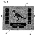
Fig. 4 is an example of selection of a dinosaur-type
display object in a skeleton selection menu display (process
P1), showing in perspective the skeleton corresponding to
the selected display object;
Fig. 5 shows in draw mode the display of an image in
the process of drawing a human-type display object selected
as in Fig. 3;
Fig. 6 shows in draw mode the display of an image in
the process of drawing a dinosaur-type display object
selected as in Fig. 4;
Fig. 7 shows a display in a screen in the outline
setting process (process P4);
Fig. 8 is a schematic diagram series composed of Figs.
8A to 8D which explain outline settings (process P4);
Fig. 9 is a first diagram series composed of Figs. 9A
to 9C which explain the algorithm for three-dimensional
conversion;
Fig. 10 is a second diagram series composed of Figs.
10A to 10D which explain the algorithm for three-dimensional
conversion;
Fig. 11 is a third diagram series composed of Figs. 11A
and 11B which explain the algorithm for three-dimensional
conversion;
Fig. 12 is a fourth diagram series composed of Figs.
12A to 12C which explain the algorithm for three-dimensional
conversion;
Fig. 13 is a fifth diagram series composed of Figs. 13A
to 13D which explain the algorithm for three-dimensional
conversion;
Fig. 14 is a set of diagrams composed of Figs. 14A and
14B showing an example of skeletal parts of a human-type
display object;
Fig. 15 is a set of diagrams composed of Figs. 15A and
15B showing an example of skeletal parts of an animal-type
display object;
Fig. 16 is a diagram which explains a case in which the
shape of an arm part is changed;
Fig. 17 is a diagram which explains a case in which the
shape of a leg part is changed;
Fig. 18 is a set of diagrams composed of Figs. 18A to
18C to explain the setting of modifier values for offense
and defense levels associated with a drawn form;
Fig. 19 is an image of a dinosaur model, displayed
using three-dimensional polygon data, drawn after selecting
the dinosaur perspective skeleton in Fig. 4;
Fig. 20 is a first image of a model generated after
drawing a human-type perspective skeleton;
Fig. 21 is a second image of a model generated after
drawing a human-type perspective skeleton; and,
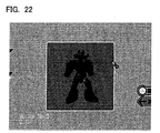
Fig. 22 is a third image of a model generated after
drawing a human-type perspective skeleton.
DESCRIPTION OF THE PREFERRED EMBODIMENTS
Fig. 1 is a block diagram of one example of information
processing equipment to which this invention is applied.
In Fig. 1, the information processing equipment has a
program data storage device or recording medium 1 (including
an optical disc and optical disc drive, or similar) on which
programs and data (including image and music data) are
stored.
In the information processing equipment, the CPU 2
executes programs, controls the entire system, and performs
coordinate calculations and similar for image display. The
system memory 3 stores programs and data necessary for the
CPU 2 to perform processing.
The boot ROM 20 stores programs and data necessary to
start up the information processing equipment. The bus
arbiter 40 controls the flow of program data between each of
the blocks of the information processing equipment and any
connected external devices. The rendering processor 41
reproduces movie data read from the program data storage
device or recording medium 1, and generates images for
display according to manipulations by the game player and
the progress of the game.
Graphic data and similar necessary for image generation
by the rendering processor 41 is stored in the graphic
memory 5. The sound processor 7 reproduces music data read
from the program data storage device or recording medium 1,
and generates sound effects and voices according to
manipulations by the game player and the progress of the
game. Sound data or similar necessary to generate sound
effects and voices is stored in the sound memory 70.
The above bus arbiter 40 is connected to a modem 9,
which connects to and performs communications with other
information processing equipment and network servers via
telephone lines. The modem 9 connected to this information
processing equipment uses telephone circuits; however, a
terminal adapter (TA) which also uses telephone circuits, or
a cable modem which uses cable TV circuits, as well as
communication equipment employing wireless communication
means using portable telephones, PHS (personal handyphone
system) devices, or optical fiber communication means or
similar, can also be used.
The bus arbiter 40 is connected to the controller 8
such as a control pad or a tablet, which outputs to the
information processing equipment information used to control
the information processing equipment or connected external
devices according to manipulations by the game player. The
controller 8 is also connected to a backup memory 80, which
stores and saves parameters and other data generated by the
program.
The information processing equipment is also connected
externally to a speaker 71 which reproduces audio signals
output from the sound processor 7, and a display monitor 6
which displays image signals output from the rendering
processor 41.
Ordinarily, information processing equipment requests
operation information from the controller 8 such as a tablet
or a control pad at prescribed time intervals; the
controller 8 is designed to output operation information
from a trigger button, touch panel, or similar to the
information processing equipment each time there is such a
request.
The information processing equipment then uses the
operation information received from the controller 8 as
parameters when the CPU 2 executes the application program
in system memory 3, causes the rendering processor 41 and
sound processor 7 to perform image processing and audio
processing reflecting operations by the game player, and
outputs images and audio to the display monitor 6 and
speaker 71.
Application of this invention is not impeded even if
the above information processing equipment is TV game
equipment, a personal computer or workstation, a telephone
set or communication device with image display functions, or
an image display device having communication and information
processing functions.
If the program executed by the above information
processing equipment is assumed to be a game program, then
the game program comprises data for display objects, in
addition to program data to control game execution.
In the application of this invention, "display objects"
refers to humans and animals, monsters, robots and other
characters, as well as automobiles, airplanes, boats,
bicycles and other vehicles, and any and all other objects
displayed by a display device which can be manipulated by
the game player.
The above bus arbiter 40 and rendering processor 41 can
be configured integrally as a DSP (digital signal processor)
4, having functions for conversion of coordinates of display
object data having three-dimensional coordinates and for
application of texture data to polygons, according to
program data controlling the game execution.
In the above conversion functions of the coordinates of
display object data, display object data having world
coordinates is converted into three-dimensional point-of-view
coordinates, and then into two-dimensional coordinates.
Display object data resulting from conversion into two-dimensional
coordinates and application of texture data is
sent to the graphic memory 5, and is successively read out
and converted into video signals for display as images on
the display monitor 6.
Based on data controlling game execution, digital
audio signals are processed by the sound processor 7,
converted into analog audio signals and reproduced as audio
by the speaker 71, while synchronized with the above image
display.
In this way, the information processing equipment which
executes the game program according to this invention,
contains a program that allows the game player to generate
display objects as part of the above game program, or as a
separate program.
When the display object generation program is part of a
competitive game program as shown in one embodiment, the
display object generation program is executed and controlled
at an appropriate time, set in advance, in the progress of
the competitive game program. It is preferable that
execution at this appropriate time be performed prior to the
stage of selection of competing display objects in the
competitive game program.
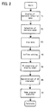
Fig. 2 shows the flow of processing of one embodiment
of a display object generation program according to this
invention.
In Fig. 2, when the display object generation program
is started, a skeleton selection menu screen is displayed on
the display device 6 (process P1). Examples of this menu
screen are shown in Fig. 3 and Fig. 4.
In the menu screen, a region I in the center displays
the perspective skeleton model of the selected display
object to be generated, and, on the periphery of region I,
there are a plurality of display object selection buttons II.
The game player uses a keyboard, mouse or other input device
8 connected to the game equipment shown in Fig. 1 to control
the movement of the pointer III, in order to specify a
desired display object selection button II (process P2).
Fig. 3 is an example in which a human-type display
object is selected, and Fig. 4 is an example in which a
dinosaur-type display object is selected; in each case, a
perspective skeleton model is displayed as superposed with
the basic shape image corresponding to the selected display
object. In this invention, parameters are set for each of a
plurality of skeletal parts constituting the perspective
skeleton model, as explained below.
As shown in Fig. 3 and Fig. 4, a perspective skeleton
model of the selected display object is displayed; when
confirming this, the game player positions the pointer III
on the confirmation button IV to confirm the input. When
skeleton model selection processing (process P2) is thus
completed, the program proceeds to draw mode (process P3).
Fig. 5 and Fig. 6 show the image display in the process
of drawing a selected human-type display object and
dinosaur-type display object in draw mode, corresponding to
Fig. 3 and Fig. 4 respectively.
These figures show perspective skeleton models with
basic shape images superposed, as described above; referring
to these basic shape images, an image input device 8 can
easily be used to move the pen pointer V on the screen,
forming an image of the outline of the display object.
Accordingly, the movement trace VI of the pen pointer V is
successively displayed.
As an aspect of this invention, the movement trace VI,
that is the outline trace, is displayed as superposed on the
displayed perspective skeleton model.
Since outline setting processing (process 4) is
performed in the next process in this invention, the
movement trace VI of the pen pointer V may be discontinuous,
any number of movement traces may overlap with each other,
and the trace need not surround the skeleton as a close
trace at this stage .
Fig. 7 shows the display of the screen in the outline
setting process (process P4). In the previous draw mode
(process P3), when the end is confirmed using a displayed
button, not shown, the outline setting process is executed.
In Fig. 7, VII is a time display symbol shown during
processing.
In this invention, a region is set for each skeletal
part of the perspective skeleton model. The movement trace
VI of the pen pointer V inputted in the previous draw mode
(process P3), is converted into closed outlines each for a
skeletal part region.
In Fig. 7, the pen trace in draw mode is converted into
closed outline traces and displayed for each of the head
portion a1, torso portion a2, hip portion a3, tail portion
a4, arm portions a5, and leg portions a6.
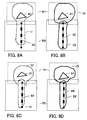
Fig. 8 is a schematic diagram which further explains
the outline setting process (process P4). Fig. 8A and Fig.
8C are examples of movement traces of the pen pointer V; Fig.
8B and Fig. 8D are figures in which outlines are set
corresponding to the movement traces of the pen pointer V in
Fig. 8A and Fig. 8C.
B1 and B2 are skeletal parts of the perspective
skeleton model; in this invention, as one feature, the
skeletal parts each have regions R1, R2. The regions R1, R2
provided for each skeletal part of the display object are
set such that parts of the regions R1, R2 overlap, with no
gap occurring between the regions R1 and R2 even when the
skeletal parts move at joints.
The movement trace t1 of the pen pointer V in Fig. 8A
is a single continuous closed trace spanning the regions R1
and R2, and encloses the two skeletal parts B1, B2. In this
example, in accordance with this invention, the movement
trace t1 of the pen pointer V is separated by the regions R1,
R2, and converted into two closed outlines in the regions R1,
R2, respectively. Fig. 8B shows the two separated outlines
tf1, tf2.
In the example of Fig. 8C, the movement trace t2 of the
pen pointer V surrounding the skeletal part B1 is not closed
within the region R1, while the movement trace t3 of the pen
pointer V surrounding the skeletal part B2 is closed.
In this example, in accordance with this invention, the
portion of the movement trace t2 of the pen pointer V which
extends into the region R2 is deleted, and the remainder is
converted into a closed outline tf3 within the region R1, as
shown in Fig. 8D. On the other hand, the trace drawn within
the region R2, that is, the movement trace t3 of the pen
pointer V surrounding the skeletal part B2, protrudes
outside the region R2. Hence as shown in Fig. 8D, this is
converted so as to be closed within the region R2.
In the above outline setting process P4, by having all
of the skeletal parts, the regions, and the movement traces
of the pen pointer V in the form of bitmap data,
calculations can be performed for conversion based on the
respective bitmap coordinates.
Returning to the flow of processing in Fig. 2, two-dimensional
(2D) display object data is generated through
the outline setting process (process P4). Next, the drawing
model of this two-dimensional display object data is
converted, for each skeletal part, into a three-dimensional
(3D) model (process P5).
In this conversion into 3D mode of the drawing model of
the two-dimensional display object data, the algorithm
described in the paper "Teddy: A Sketching Interface for 3D
Freedom Design" presented at ACMSIGGRAPH '99 can be applied.
Here, in order to facilitate understanding, the
procedure of the 3D conversion algorithm described in the
above paper is explained briefly, using analogous drawings.
Fig. 9 through Fig. 12 are figures used to explain the
algorithm for 3D conversion. As explained above, closed
movement traces of the pen pointer V are obtained for each
skeletal part by means of the outline setting process
(process P4).
Fig. 9A is a figure in which, for a closed movement
trace of the pen pointer V obtained for a single skeletal
part, all the edges are formed using line segments of a
fixed length. Next, the endpoints of the edges formed are
connected to form a plurality of triangles (see Fig. 9B).
At this time, the triangles thus formed can be
classified into three types. The first type is for triangles
two edges of which are external edges (90 to 93 in Fig. 9B);
the second type is for triangles (connecting triangles) no
edges of which are external (94 and 95 in Fig. 9B). The
third type is for triangles (sleeve triangles) one edge of
which is external (96 to 100 in Fig. 9B).
If the centers of the above connecting triangles 94, 95
and the centers of the edges of the sleeve triangles 96 to
100 are connected, a backbone like that shown by the bold
lines P in Fig. 9C is obtained. In the above paper, the
further pruning of unnecessary branches is explained.
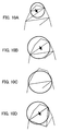
That is, as shown in Fig. 10, a circle is drawn having
as diameter the interior edge of a triangle of the above
first type, having two exterior edges (90 to 93 in Fig. 9B),
and if a vertex of the triangle is within the above circle,
the above interior edge is eliminated, and the triangle is
united with the neighboring triangle (Fig. 10A and Fig. 10B).
If the neighboring triangle to be united with the triangle
is a sleeve triangle as described above, the united polygon
is a polygon shape having three exterior edges (Fig. 10B).
Next, a circle having as diameter the interior edge of
the united polygon is similarly drawn, and a judgment is
made as to whether the vertices of the polygon are contained
within the circle. The above processing is repeated until at
least one of the vertices of the above polygon is outside
the above circle, or until the neighboring triangle to be
united with the polygon is a connecting triangle of the
second type described above, with no exterior edges.
Fig. 10C shows a case in which some of the vertices of
the polygon are outside the circle. Fig. 10D shows a case in
which the neighboring triangle to be united is a connecting
triangle of the second type described above, with no
exterior edges.
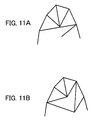
In the case of Fig. 10C, the vertices of the polygon
and the midpoint of the interior edge are connected (see Fig.
11A); in the case of the example shown in Fig. 10D, the
exterior-edge vertices of the polygon and the center point
of the connecting triangle are connected (see Fig. 11B).
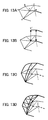
In this way, a two-dimensional polygonal figure is
obtained in which the figure of Fig. 9 is subdivided into
triangles (Fig. 12A). Next, by connecting the midpoints of
the interior edges of sleeve triangles and connecting
triangles, the triangles are divided by a backbone indicated
by the bold line P (Fig. 12B). The polygons P1, P2, P3
resulting from this are divided into triangles, so that a
complete two-dimensional triangular mesh is obtained (Fig.
12C).
The two-dimensional triangular mesh thus obtained is
then expanded and converted into a three-dimensional mesh
structure, following the algorithm described in the above
paper. The algorithm for expansion and conversion to a
three-dimensional mesh structure described in this paper is
explained using Fig. 13.
The vertex of a backbone edge as obtained above is
raised up from the plane in which vertices X, a, b, c, d,
and e lie, in proportion to the average value of the
distances between the vertex and vertices directly connected
to it. For example, in Fig. 13A, the vertex X of the
backbone edge (shown in bold) is directly connected to the
vertices a, b, c, d, e. Hence the vertex X is raised by an
amount equal to the average of the distances between the
vertex X and the vertex a, the vertex X and the vertex b,
the vertex X and the vertex c, the vertex X and the vertex d,
and the vertex X and the vertex e, and is converted to the
vertex X' (Fig. 13B).
Further, the vertex X' converted in this way and the
vertices of external edges are connected by the arcs of a
quarter-sphere (Fig. 13C). An appropriate polygon mesh is
obtained by binding together raised neighboring edges (Fig.
13D).
Accordingly, the two-dimensional bitmap data for
drawing as shown in Fig. 7 is expanded and converted into
three-dimensional polygon data for each of the skeletal
parts of the drawing model. By this means, 3D conversion of
the drawing model (process P5) is completed. The polygon
data of a 3D display object obtained in this way is stored
or registered in RAM 3 (process P6).
As a concrete embodiment according to the present
invention in which an attribute parameter (modified
parameter), obtained by modifying the attribute parameter
(base parameter) of the basic body according to the ratio of
the outline trace associated with the skeleton model to the
basic body data, is attached to the data of the expanded and
converted three-dimensional display object image, when
registering this 3D display object polygon data, attribute
parameters characterizing the behavior mode of the display
object corresponding to the polygon data of the 3D display
object are attached. Hence attached parameters are set
together with the polygon data of the 3D display object in
the above RAM 3.
As one embodiment of this invention, a plurality of
attribute parameters are prepared as attribute parameters
characterizing the behavior mode. Each of these attribute
parameters comprises a "base parameter" and a "modified
parameter".
The base parameter is predetermined for the display
object and can be accumulated in the course of the game.
That is, a fixed value is given as an initial value, and in
the course of the game, points are added each time
prescribed conditions are satisfied.
On the other hand, the modified parameter is a
parameter provided corresponding to the shape of the display
object when the shape of the display object is generated for
the first time through drawing by the game player, or when
the shape is redrawn.
First, three-dimensional basic body data for an average
physique is prepared in advance for each of the plurality of
display objects prepared in the skeleton selection menu
display (process P1) of this invention. The CPU 2 calculates
various parameters (attribute parameters) as shown below by
comparing the three-dimensional basic body data with drawn
figures.
As an embodiment, attributes are defined for each
skeletal part constituting each display object. For example,
the skeleton shown in Fig. 14 for a human-type display
object has head, arm, torso, hip, and leg parts; power
parameters as one type of the above-described attribute
parameters are defined for part attributes for the arm and
leg, and a speed parameters as another type of the above-described
attribute parameter is defined for the leg.
In Fig. 15, an animal-type skeleton is shown; the
skeleton of Fig. 15A has head, torso, hip, leg 1, leg 2, and
tail parts, while the skeleton of Fig. 15B has head, arm,
torso, hip, leg 1, leg 2, and tail parts. Power parameters
are set as part attributes for the head, arm and leg 1, and
speed parameters are set for the leg 1 and leg 2.
Based on such skeletal part information, parameter
values such as the following are used for display objects
for which outlines are drawn.
- Total volume: Total volume of all parts.
- Power parts volume total: The total volume of all power
parts defined for each skeleton, where parts having power
as a part attribute are called power parts.
- Power parts volume ratio: The proportion of the power
parts volume total in the total volume ((power parts volume
total)/(total volume)).
- Speed parts volume total: The total volume of all speed
parts defined for each skeleton, where parts having speed
as a part attribute are called speed parts.
- Speed parts volume ratio: The proportion of the speed
parts volume total in the total volume ((speed parts volume
total)/(total volume)).
- Average volume: The average volume of part units ((total
volume)/(total number of parts)).
According to one exemplary method for modifying the
attribute parameter of the basic body according to the ratio
of the outline trace associated with the skeleton model to
the basic body data, the total power parts volume and power
parts volume ratio for a drawn display object, determined as
described above, are compared with those of the
corresponding three-dimensional basic body to set modifier
values for the drawn display objects as follows.
Determination of a modifier value by comparison of
total power parts volume: For every 10% that the volume of
the drawn parts is larger than that of the basic body, it is
modified by +1. Conversely, for every 10% that the drawn
parts volume is smaller than that of the basic body, the
value is modified by -1.
Determination of a modifier value by comparison of
power parts volume ratio: For every 10% that the volume
ratio of the drawn parts is larger than that of the basic
body, the value is modified by +1. Conversely, for every 10%
that the drawn parts volume ratio is smaller than that of
the basic body, the value is modified by -1.
Modified parameters are determined from the base
parameters as follows.
If the power parameter of the basic body as one type of
the base parameters is taken to be "5", then the modified
power parameter of the drawn display object is 5 + (modifier
value for the total power parts volume) + (modifier value
for the power parts volume ratio). Accordingly, when the
volume ratio of the drawn parts is 10% larger than that of
the basic body, the modified power parameter is 5+1 = 6.
Similarly to the above calculation of the power
parameter for a drawn display object, the modified speed
parameter for a drawn display object will be 5 + (total
speed parts volume modifier value) + (speed parts volume
ratio modifier value). Here the speed parameter of the basic
body as one type of the base parameters is taken to be "5".
In this way, both the power parameter and the speed
parameter of a drawn display object are related to the
volume of skeletal parts concerned with power and speed.
Hence the game player can, when drawing a display object,
draw part shapes in anticipation of the desired behavior
modes of the display object. This is explained in Fig. 16
and Fig. 17.
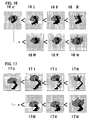
Fig. 16 is a diagram which explains a case in which the
shape of an arm part is changed.
In Fig. 16, compared with the basic shape (16O), the
arm may be lengthened (16I), made thicker (16II), and the
fractional volume of the arm may be increased (16III). By
this means, a display object may be endowed with a strong
punching strength attribute, in a shape which is suitable
for generating an animal-type display object with arm
strength, such as a gorilla.
On the other hand, compared with the basic shape (16O),
the arm may be made shorter (16IV), thinner (16V), and the
fractional volume of the arm may be reduced (16VI). By this
means, an arm with little power, which is only ornamental,
can be generated.
Fig. 17 is a diagram which explains a case in which the
shape of a leg part is changed.
In Fig. 17, compared with the basic shape (17O), the
leg may be lengthened (17I), made thinner (17II), and the
fractional volume of the leg may be increased (17III). By
this means, a display object may be endowed with a high
speed attribute, in a shape which is suitable for generating
an animal-type display object with fast running speed, such
as an impala.
Or, compared with the basic shape (17O), the leg may be
made shorter (17IV), thicker (17V), and the fractional
volume of the leg may be reduced (17VI). By this means, the
attributes of an animal-type display object in a heavy
weight class with considerable power can be imparted, in a
shape suitable for generating a massive animal-type display
object, such as an elephant.
In the above explanation, a method is employed in which
attribute parameters are set in association with the three-dimensional
volumes of display objects; but the present
invention is not limited to this, and the area of the two-dimensional
display object image as drawn may be compared
with the area of the corresponding basic body.
Further, modifier values for the attack and defense
levels may also be set corresponding to drawn shapes, as
explained in Fig. 18.
As one example, the above modifier values for the
attack and defense levels may be set according to the number
of protrusions constituting each part of the drawn model. In
Fig. 18A, circled portions are protrusions; for example, a
portion having an angle of less than 45° may be defined as a
protrusion.
Modifier values for the attack and defense levels are
set corresponding to the number of protrusions constituting
each of the torso, arm, and leg parts. As an example, these
values may be given as follows.
When the number of protrusions in a torso part is 0, a
modifier value for the attack power level of 1 is assigned.
When the number of protrusions is 2 to 4, the modifier value
for the short-range attack power level is set to be 1. When
the number of protrusions is 5 or greater, the modifier
value for the long-range attack power level is set to be 1.
When the number of protrusions in an arm part is 0, a
modifier value for the defense power level of 0 is assigned.
When the number of protrusions is 2 to 4, the modifier value
for the long-range attack power level is set to be 2. When
the number of protrusions is 5 or more, the modifier value
for the long-range attack power level is set to be 3.
When the number of protrusions in a leg part is 0, a
modifier value for the attack power level of 2 is assigned.
When the number of protrusions is 2 to 4, the modifier value
for the short-range attack power level is set to be 2. When
the number of protrusions is 5 or more, the modifier value
for the attack power level at crossing range is set to be 3.
As shown in Fig. 18B, modifier values for the attack
and defense power levels can also be set for each of the
torso, arm and leg parts according to the "smoothness" of
each part shape. That is, similarly to the explanation of
Fig. 18A, modifier values for the attack and defense levels
can be set according to whether the shape, for each torso,
arm and leg part, is "smooth", "rough", or "extremely rough".
Further, as shown in Fig. 18C, similarly to the
explanation of Fig. 18A, modifier values for the attack and
defense levels can be set according to the stroke length
(short, average, long) of parts for each torso, arm, and leg
part.
Also, parameter values can be changed according to the
type of texture applied to a drawn display object. That is,
in the processing flow of Fig. 2, when registering three-dimensional
display object data, the game player who has
drawn an object can also select a texture appropriate to the
display object, as part of the attached parameter values.
Modifier values set for the selected texture are
attached, and the texture corresponding to the modifier
values is applied during drawing. Texture colors such as the
following can be set for each attribute or modifier value.
| Attribute | Color | Modified value | Modified value |
| None | Gray to black | 0 | 0 |
| Earth | Yellow to dark brown | -3 | +3 |
| Water | Light blue to blue | 1 | +1 |
| Fire | Orange to red | 1 | 0 |
| Wind | Light green to dark green | -1 | +1 |
| Heaviness | Purple to black | -2 | +2 |
| Ice | White to light blue | +1 | 0 |
| Light | White to yellow (glossy) | +3 | -3 |
| Thunder | Yellow to yellow-green (metallic) | +4 | -3 |
Here the parameters imparted to a drawn display object
as explained above are not imparted only when the object is
drawn, but are updated to newly modified parameters each
time the drawn display object data is updated.
In addition to the above parameter settings, parameters
relating to the lifetime of the display object can also be
set.
As explained above, the generated three-dimensional
display object data is, as a display object to be
manipulated by the game player in the game program execution
process (process P7), subjected to the existing texture
processing according to the attached attribute parameter
values and processing to convert coordinates to a two-dimensional
screen, and then is displayed on the display
device 6.
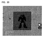
Fig. 19 is an image of a dinosaur model, displayed
using 3D polygon data, drawn after selecting the dinosaur
perspective skeleton in Fig. 4. Fig. 20 through Fig. 22 show
images of models generated by drawing from a human-type
perspective skeleton. As is understood from a comparison of
Fig. 20 through Fig. 22, even for the same model, the
external image changes according to the manner of drawing
the outline in draw mode, the texture selected and similar.
By means of this invention, display objects can easily
be generated with the shape preferred by the game player
himself. Further, the generated display object can be
employed as a display object to be manipulated by the game
player himself in the computer game. By this means, the game
player can enjoy the game by manipulating a display object
matched to the game player's preferences with greater
variety.
Further, display object data with three-dimensional
coordinates is generated in association with a skeleton
model serving as a basis for movement of the display object,
so that movement of the created display object can be easily
controlled. As a result, the game player can relate his
feeling more closely to the display object he has himself
created.
Also, attribute parameters are set corresponding to the
characteristics of a generated display object, so that
during game program execution the display object can be
endowed with movement according to the attribute parameters.
Such movement during program execution is also called
the behavior mode in this specification. Accordingly, the
behavior mode of the generated three-dimensional display
object can be characterized by the above-described attribute
parameters. Slow movement, quick movement, movement with its
direction slowly changing, movement with its direction
rapidly changing, and other similar movements can be
enumerated as examples of the characterized behavior modes.
Characterization of the behavior mode can also be
achieved by selecting motions from among a multiple number
of motion patterns (motion data) according to the length
and/or thickness of the legs as shown in Fig. 17, to change
the motions themselves. For example, for a display object
having thick and short legs, one can select a motion data in
which the object drags its feet as it walks. For a display
object having thin and long legs, one can select a motion
data in which the object strides briskly. Such selection can
be related not only to the legs as described above but also
to the size and shape of head, the thickness and length of
arms and torso, etc. Hereupon, it is to be noted that the
embodiments explained with reference to the above drawings
are intended to aid understanding of this invention, and do
not limit the scope of the invention.