EP1207401A2 - MR imaging method, residual magnetization amount measuring method and MRI apparatus - Google Patents
MR imaging method, residual magnetization amount measuring method and MRI apparatus Download PDFInfo
- Publication number
- EP1207401A2 EP1207401A2 EP01309249A EP01309249A EP1207401A2 EP 1207401 A2 EP1207401 A2 EP 1207401A2 EP 01309249 A EP01309249 A EP 01309249A EP 01309249 A EP01309249 A EP 01309249A EP 1207401 A2 EP1207401 A2 EP 1207401A2
- Authority
- EP
- European Patent Office
- Prior art keywords
- pulse
- gradient
- applying
- residual magnetization
- echo
- Prior art date
- Legal status (The legal status is an assumption and is not a legal conclusion. Google has not performed a legal analysis and makes no representation as to the accuracy of the status listed.)
- Ceased
Links
Images

Classifications
-
- A—HUMAN NECESSITIES
- A61—MEDICAL OR VETERINARY SCIENCE; HYGIENE
- A61B—DIAGNOSIS; SURGERY; IDENTIFICATION
- A61B5/00—Measuring for diagnostic purposes; Identification of persons
- A61B5/05—Detecting, measuring or recording for diagnosis by means of electric currents or magnetic fields; Measuring using microwaves or radio waves
- A61B5/055—Detecting, measuring or recording for diagnosis by means of electric currents or magnetic fields; Measuring using microwaves or radio waves involving electronic [EMR] or nuclear [NMR] magnetic resonance, e.g. magnetic resonance imaging
-
- G—PHYSICS
- G01—MEASURING; TESTING
- G01R—MEASURING ELECTRIC VARIABLES; MEASURING MAGNETIC VARIABLES
- G01R33/00—Arrangements or instruments for measuring magnetic variables
- G01R33/20—Arrangements or instruments for measuring magnetic variables involving magnetic resonance
- G01R33/44—Arrangements or instruments for measuring magnetic variables involving magnetic resonance using nuclear magnetic resonance [NMR]
- G01R33/48—NMR imaging systems
- G01R33/54—Signal processing systems, e.g. using pulse sequences ; Generation or control of pulse sequences; Operator console
- G01R33/56—Image enhancement or correction, e.g. subtraction or averaging techniques, e.g. improvement of signal-to-noise ratio and resolution
- G01R33/565—Correction of image distortions, e.g. due to magnetic field inhomogeneities
- G01R33/56554—Correction of image distortions, e.g. due to magnetic field inhomogeneities caused by acquiring plural, differently encoded echo signals after one RF excitation, e.g. correction for readout gradients of alternating polarity in EPI
-
- G—PHYSICS
- G01—MEASURING; TESTING
- G01R—MEASURING ELECTRIC VARIABLES; MEASURING MAGNETIC VARIABLES
- G01R33/00—Arrangements or instruments for measuring magnetic variables
- G01R33/20—Arrangements or instruments for measuring magnetic variables involving magnetic resonance
- G01R33/44—Arrangements or instruments for measuring magnetic variables involving magnetic resonance using nuclear magnetic resonance [NMR]
- G01R33/48—NMR imaging systems
- G01R33/54—Signal processing systems, e.g. using pulse sequences ; Generation or control of pulse sequences; Operator console
- G01R33/56—Image enhancement or correction, e.g. subtraction or averaging techniques, e.g. improvement of signal-to-noise ratio and resolution
- G01R33/565—Correction of image distortions, e.g. due to magnetic field inhomogeneities
Definitions
- the present invention relates to an MR imaging method, residual magnetization amount measuring method and MRI (magnetic resonance imaging) apparatus, and more particularly to an MR imaging method capable of restraining residual magnetization caused by a previous pulse sequence from affecting a current pulse sequence, a residual magnetization amount measuring method for verifying a demagnetizing effect, and an MRI apparatus for implementing such methods.
- MR imaging methods are disclosed in which a corrective component is appended to a phase encoder gradient or rewind gradient for restraining residual magnetization caused by a phase encoder gradient from affecting an echo next to an echo that corresponds to the phase encoder gradient.
- a pulse sequence involving transmitting an RF pulse, applying a phase encoder gradient and receiving an NMR signal from a subject is repeated with the phase encoding amount varied to thereby collect data for filling the k-space.
- the aforementioned conventional techniques restrain the effect of residual magnetization within one pulse sequence, and do not restrain residual magnetization caused by a previous pulse sequence from affecting the current pulse sequence.
- the present invention therefore seeks to provide an MR imaging method capable of restraining residual magnetization caused by a previous pulse sequence from affecting the current pulse sequence, a residual magnetization amount measuring method for verifying a demagnetizing effect, and an MRI apparatus for implementing such methods.
- the present invention provides an MR imaging method for transmitting an RF pulse, applying a phase encoder gradient, receiving an NMR signal from a subject and producing an MR image based on said NMR signal, characterized in: prior to transmitting the RF pulse, consecutively applying first through I-th ( ⁇ 2) gradient pulses having alternately inverting polarity and pulse heights reduced in order.
- first through I-th gradient pulses having alternately inverting polarity and pulse heights reduced in order are consecutively applied prior to substantially beginning a pulse sequence for acquiring data
- residual magnetization of a previous pulse sequence is demagnetized, and thereafter the pulse sequence for acquiring data is substantially begun. Therefore, residual magnetization caused by the previous pulse sequence can be restrained from affecting the current pulse sequence.
- the present invention provides the MR imaging method of the aforementioned configuration, characterized in that said first gradient pulse has a pulse height such as to saturate residual magnetization.
- the amount of the residual magnetization is always constant. For example, in a pulse sequence according to a spin echo technique, while a varying amount of residual magnetization causes artifacts on an MR image, an always constant amount of residual magnetization does not generate artifacts on an MR image.
- I 4.
- the present invention provides the MR imaging method of the aforementioned configuration, characterized in that the first through I-th gradient pulses have trapezoidal pulse waveforms.
- the pulse waveforms as trapezoids, they can be raised at the maximum slew rate possible with the hardware.
- the present invention provides a residual magnetization amount measuring method characterized in: consecutively applying first through I-th ( ⁇ 2) gradient pulses having alternately inverting polarity and pulse heights reduced in order; applying a 90° RF pulse; applying a 180° RF pulse; observing a first echo while applying a read gradient; transmitting a 180° RF pulse; observing a second echo while applying a read gradient; and measuring a residual magnetization amount from offsets of echo peaks of said first and second echoes.
- the effect of residual magnetization after applying the gradient pulses appears as an offset of an echo peak from an echo center.
- the offset of an echo peak from an echo center is, however, difficult to measure because the echo center is difficult to identify when a single echo is taken.
- an echo peak of a first echo and that of a second echo are compared. Since an offset of the echo peak from the echo center of the first echo and an offset of the echo peak from the echo center of the second echo are in opposite directions, half of the offsets of the echo peaks of the first and second echoes gives the offset of an echo peak from an echo center. Hence, the residual magnetization amount can be determined from the offset. That is, the effect of applying the gradient pulses can be evaluated.
- the present invention provides the MR imaging method of the aforementioned configuration, characterized in adjusting at least one of the pulse height and the pulse width of the second through I-th gradient pulses based on the residual magnetization amount measured by the residual magnetization amount measuring method of the aforementioned configuration.
- the pulse width and the pulse height of the gradient pulses can be optimized.
- the present invention provides the MR imaging method of the aforementioned configuration, characterized in that the pulse height of an i-th gradient pulse is half the pulse height of an (i - 1)-th gradient pulse.
- the processing can be simplified.
- the present invention provides the MR imaging method of the aforementioned configuration, characterized in that the pulse widths of the first through I-th gradient pulses are substantially the same.
- the processing can be simplified.
- the present invention provides the MR imaging method of the aforementioned configuration, characterized in applying the first through I-th gradient pulses to a gradient axis to which a phase encoder gradient is applied.
- the effect of residual magnetization caused by a phase encoder gradient is particularly reduced by applying the aforementioned gradient pulses to a gradient axis to which the phase encoder gradient is applied.
- the above gradient pulses are applied to those gradient axes.
- the present invention provides an MRI apparatus comprising RF pulse transmitting means, gradient pulse applying means and NMR signal receiving means, said apparatus controlling said means to transmit an RF pulse, apply a phase encoder gradient, receive an NMR signal from a subject and produce an MR image based on said NMR signal, characterized in comprising: residual magnetization demagnetizing means for, prior to transmitting the RF pulse, consecutively applying first through I-th ( ⁇ 2) gradient pulses having alternately inverting polarity and pulse heights reduced in order.
- the MR imaging method of the first aspect can be suitably implemented.
- the present invention provides the MRI apparatus of the aforementioned configuration, characterized in that said first gradient pulse has a pulse height such as to saturate residual magnetization.
- the MR imaging method of the second aspect can be suitably implemented.
- the MR imaging method of the third aspect can be suitably implemented.
- the present invention provides the MRI apparatus of the aforementioned configuration, characterized in that the first through I-th gradient pulses have trapezoidal pulse waveforms.
- the MR imaging method of the fourth aspect can be suitably implemented.
- the present invention provides an MRI apparatus comprising RF pulse transmitting means, gradient pulse applying means and NMR signal receiving means, said apparatus controlling said means to transmit an RF pulse, apply a phase encoder gradient, receive an NMR signal from a subject and produce an MR image based on said NMR signal, characterized in comprising: residual magnetization amount measuring means for consecutively applying first through I-th ( ⁇ 2) gradient pulses having alternately inverting polarity and pulse heights reduced in order; applying a 90° RF pulse; applying a 180° RF pulse; observing a first echo while applying a read gradient; transmitting a 180° RF pulse; observing a second echo while applying a read gradient; and measuring a residual magnetization amount from offsets of echo peaks of said first and second echoes.
- the MR imaging method of the fifth aspect can be suitably implemented.
- the present invention provides the MRI apparatus of the aforementioned configuration, characterized in adjusting at least one of the pulse height and the pulse width of the second through I-th gradient pulses based on the residual magnetization amount measured by the residual magnetization amount measuring means of the aforementioned configuration.
- the MR imaging method of the sixth aspect can be suitably implemented.
- the present invention provides the MRI apparatus of the aforementioned configuration, characterized in that the pulse height of an i-th gradient pulse is half the pulse height of an (i - 1)-th gradient pulse.
- the MR imaging method of the seventh aspect can be suitably implemented.
- the present invention provides the MRI apparatus of the aforementioned configuration, characterized in that the pulse widths of the first through I-th gradient pulses are substantially the same.
- the MR imaging method of the eighth aspect can be suitably implemented.
- the present invention provides the MRI apparatus of the aforementioned configuration, characterized in applying the first through I-th gradient pulses to a gradient axis to which a phase encoder gradient is applied.
- the MR imaging method of the ninth aspect can be suitably implemented.
- a demagnetizing gradient pulse sequence is applied prior to an MR imaging pulse sequence to cancel residual magnetization caused by a previous MR imaging pulse sequence and reduce the residual magnetization.
- the residual magnetization caused by the previous MR imaging pulse sequence can be restrained from affecting an MR image, and the image quality of MR images can be improved.
- the residual magnetization amount caused by the demagnetizing gradient pulse sequence can be measured.
- the demagnetizing effect of the demagnetizing gradient pulse sequence can be evaluated.
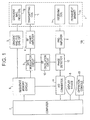
- Fig. 1 is a block diagram of an MRI apparatus in accordance with one embodiment of the present invention.
- a magnet assembly 1 has an empty portion (bore) therein for inserting a subject, and surrounding the empty portion are disposed a permanent magnet 1p for applying a constant main magnetic field to the subject; a gradient magnetic field coil 1g for generating gradient magnetic fields along X-, Y- and Z-axes; a transmitting coil 1t for supplying an RF pulse to excite spins of atomic nuclei within the subject; and a receiving coil 1r for detecting an NMR signal from the subject.
- the gradient magnetic field coil 1g, transmitting coil 1t and receiving coil 1r are connected to a gradient magnetic field driving circuit 3, an RF power amplifier 4 and a preamplifier 5, respectively.
- a superconductive magnet may be employed instead of the permanent magnet 1p.
- a sequence memory circuit 8 operates the gradient magnetic field driving circuit 3 based on a stored pulse sequence in response to instructions from a computer 7 to thereby generate the gradient magnetic fields from the gradient magnetic field coil 1g in the magnet assembly 1.
- the sequence memory circuit 8 also operates a gate modulation circuit 9 to modulate a carrier output signal from an RF oscillation circuit 10 into a pulsed signal having a predefined timing and envelope shape.
- the pulsed signal is applied to the RF power amplifier 4 as an RF pulse, power-amplified in the RF power amplifier 4, and applied to the transmitting coil 1t in the magnet assembly 1 to selectively excite a desired imaging plane.
- the preamplifier 5 amplifies an NMR signal from the subject detected at the receiving coil 1r in the magnet assembly 1, and inputs the signal to a phase detector 12.
- the phase detector 12 phase-detects the NMR signal from the preamplifier 5 with reference to the carrier output signal from the RF oscillation circuit 10, and supplies the phase-detected signal to an A/D converter 11.
- the A/D converter 11 converts the phase-detected analog signal into digital data, and inputs it to the computer 7.
- the computer 7 reads the digital data from the A/D converter 11, and performs an image reconstruction operation to produce an MR image of the imaging plane.
- the computer 7 is also responsible for overall control such as receiving information input from an operating console 13.
- a display device 6 displays the MR image.
- Fig. 2 is a flow chart of residual magnetization amount measuring processing in accordance with the present invention.
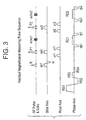
- Step E1 data of first and second echoes echo1 and echo2 are collected by a residual magnetization measuring pulse sequence shown in Fig. 3.
- first through fourth gradient pulses RS1 ⁇ RS4 are consecutively applied to the phase axis.
- the first through fourth gradient pulses RS1 ⁇ RS4 have trapezoidal waveforms, alternately inverting polarity and pulse heights halved in order.
- the pulse height of the first gradient pulse RS1 is such that it saturates the residual magnetization.
- the pulse widths of the first through fourth gradient pulses RS1 ⁇ RS4 are substantially the same.
- an excitation pulse R is transmitted and a slice gradient ss1 is applied to the slice axis.
- a first inversion pulse P1 is transmitted and a slice gradient ss2 is applied to the slice axis, and further first crusher gradients cr1 are applied to the read axis before and after the first inversion pulse P1.
- a dephaser gradient dp1 is applied to the phase axis, and an NMR signal of the first echo echo1 is then received while applying a read gradient RD1 to the phase axis, whereafter a rephaser gradient rp1 equal to the dephaser gradient dp1 is applied to the phase axis.
- a second inversion pulse P2 is transmitted and a slice gradient ss3 is applied to the slice axis, and further second crusher gradients cr2 are applied to the read axis before and after the second inversion pulse P2.
- a dephaser gradient dp2 is applied to the phase axis, and an NMR signal of the second echo echo2 is then received while applying a read gradient RD2 to the phase axis, whereafter a rephaser gradient rp2 equal to the dephaser gradient dp2 is applied to the phase axis.
- the crusher gradients cr1 and cr2 are applied in order to eliminate a stimulated echo and FID (free induction decay) signal, which disturb the measurement of phase error, they may be omitted.
- Step E2 an offset of an echo peak is determined from the data of the first and second echoes echo1 and echo2, and a residual magnetization amount ⁇ is determined from the offset of an echo peak.
- the residual magnetization amount ⁇ measured by the above process represents the magnitude of residual magnetization caused by the first through fourth gradient pulses RS1 ⁇ RS4.
- the residual magnetization amount ⁇ is greater than the allowed value, the residual magnetization amount ⁇ is repeatedly measured after modifying the pulse heights of the second through fourth gradient pulses RS2 ⁇ RS4.
- the first through fourth gradient pulses RS1 ⁇ RS4 at that time are determined as a demagnetizing gradient pulse sequence.
- the pulse width is preferably optimized in a way similar to the above-described process.
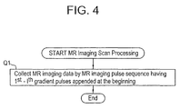
- Fig. 4 is a flow chart of MR imaging scan processing.
- Step Q1 the demagnetizing gradient pulse sequence of the first through fourth gradient pulses RS1 ⁇ RS4 determined as above are first applied, and subsequently MR imaging data are collected by an MR imaging pulse sequence that executes an ordinary MR imaging pulse sequence.
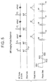
- Fig. 5 exemplarily shows an MR imaging pulse sequence in which the present invention is applied to the fast spin echo technique.
- the first through fourth gradient pulses RS1 ⁇ RS4 are consecutively applied to the phase axis.
- an ordinary MR imaging pulse sequence according to the fast spin echo technique is executed. Specifically, an excitation pulse R and a slice gradient ss1 are applied. Next, a first inversion pulse P1 and a slice gradient ss2 are applied. Next, a phase encoder gradient pe is applied to the phase axis. Next, an NMR signal of a first echo echo1 is received while applying a read gradient rd to the phase axis. Next, a rewinder gradient rw is applied to the phase axis. Subsequently, a second inversion pulse P2 and a slice gradient ss3 are applied. Next, a phase encoder gradient pe is applied to the phase axis.
- an NMR signal of a second echo echo2 is received while applying a read gradient rd to the phase axis.
- a rewinder gradient rw is applied to the phase axis.
- NMR signals are received in a similar way with the phase encoding amount varied. This MR imaging pulse sequence is repeated to collect data filling the k-space.
- a demagnetizing gradient pulse sequence of the first through fourth gradient pulses RS1 ⁇ RS4 are consecutively applied at the beginning of an MR imaging pulse sequence, residual magnetization due to a previous MR imaging pulse sequence can be removed out. Thereafter, an ordinary MR imaging pulse sequence is executed, and therefore data can be collected without being affected by the residual magnetization of the previous MR imaging pulse sequence, thereby improving the image quality of an MR image.
- the present invention is not limited to an MR imaging pulse sequence according to the fast spin echo technique but may be applied to any MR imaging pulse sequence.
Landscapes
- Physics & Mathematics (AREA)
- Health & Medical Sciences (AREA)
- Nuclear Medicine, Radiotherapy & Molecular Imaging (AREA)
- Life Sciences & Earth Sciences (AREA)
- General Health & Medical Sciences (AREA)
- Radiology & Medical Imaging (AREA)
- Engineering & Computer Science (AREA)
- High Energy & Nuclear Physics (AREA)
- Signal Processing (AREA)
- General Physics & Mathematics (AREA)
- Condensed Matter Physics & Semiconductors (AREA)
- Medical Informatics (AREA)
- Pathology (AREA)
- Biomedical Technology (AREA)
- Heart & Thoracic Surgery (AREA)
- Biophysics (AREA)
- Molecular Biology (AREA)
- Surgery (AREA)
- Animal Behavior & Ethology (AREA)
- Public Health (AREA)
- Veterinary Medicine (AREA)
- Magnetic Resonance Imaging Apparatus (AREA)
Abstract
Description
- The present invention relates to an MR imaging method, residual magnetization amount measuring method and MRI (magnetic resonance imaging) apparatus, and more particularly to an MR imaging method capable of restraining residual magnetization caused by a previous pulse sequence from affecting a current pulse sequence, a residual magnetization amount measuring method for verifying a demagnetizing effect, and an MRI apparatus for implementing such methods.
- In the publications of Japanese Patent Application Laid Open Nos. H8-322817 and H10-75940, MR imaging methods are disclosed in which a corrective component is appended to a phase encoder gradient or rewind gradient for restraining residual magnetization caused by a phase encoder gradient from affecting an echo next to an echo that corresponds to the phase encoder gradient.
- In MR imaging, a pulse sequence involving transmitting an RF pulse, applying a phase encoder gradient and receiving an NMR signal from a subject is repeated with the phase encoding amount varied to thereby collect data for filling the k-space.
- The aforementioned conventional techniques restrain the effect of residual magnetization within one pulse sequence, and do not restrain residual magnetization caused by a previous pulse sequence from affecting the current pulse sequence.
- The present invention therefore seeks to provide an MR imaging method capable of restraining residual magnetization caused by a previous pulse sequence from affecting the current pulse sequence, a residual magnetization amount measuring method for verifying a demagnetizing effect, and an MRI apparatus for implementing such methods.
- In its first aspect, the present invention provides an MR imaging method for transmitting an RF pulse, applying a phase encoder gradient, receiving an NMR signal from a subject and producing an MR image based on said NMR signal, characterized in: prior to transmitting the RF pulse, consecutively applying first through I-th (≥ 2) gradient pulses having alternately inverting polarity and pulse heights reduced in order.
- In accordance with the MR imaging method of the first aspect, since first through I-th gradient pulses having alternately inverting polarity and pulse heights reduced in order are consecutively applied prior to substantially beginning a pulse sequence for acquiring data, residual magnetization of a previous pulse sequence is demagnetized, and thereafter the pulse sequence for acquiring data is substantially begun. Therefore, residual magnetization caused by the previous pulse sequence can be restrained from affecting the current pulse sequence.
- In its second aspect, the present invention provides the MR imaging method of the aforementioned configuration, characterized in that said first gradient pulse has a pulse height such as to saturate residual magnetization.
- In accordance with the MR imaging method of the second aspect, since a first gradient pulse having a pulse height such as to saturate residual magnetization is applied, even if residual magnetization remains after applying the I-th gradient pulse, the amount of the residual magnetization is always constant. For example, in a pulse sequence according to a spin echo technique, while a varying amount of residual magnetization causes artifacts on an MR image, an always constant amount of residual magnetization does not generate artifacts on an MR image. On the other hand, in a pulse sequence according to a fast spin echo technique, even a constant amount of residual magnetization causes artifacts on an MR image as it stands because an offset in an odd-numbered echo and an offset in an even-numbered echo are in opposite directions; however, the offset amounts are constant and therefore it is possible to correct data. Thus, residual magnetization caused by the previous pulse sequence can be restrained from affecting the current pulse sequence.
- In its third aspect, the present invention provides the MR imaging method of the aforementioned configuration, characterized in that I = 4.
- If I is increased, residual magnetization can be further reduced but this processing is time consuming. On the other hand, if I is decreased, the processing time can be reduced but the effect of decreasing residual magnetization is also reduced.
- Therefore, in accordance with the MR imaging method of the third aspect, I = 4. Thus, tradeoff between the effect of decreasing residual magnetization and the processing time can be optimized.
- In its fourth aspect, the present invention provides the MR imaging method of the aforementioned configuration, characterized in that the first through I-th gradient pulses have trapezoidal pulse waveforms.
- In accordance with the MR imaging method of the fourth aspect, by shaping the pulse waveforms as trapezoids, they can be raised at the maximum slew rate possible with the hardware.
- In its fifth aspect, the present invention provides a residual magnetization amount measuring method characterized in: consecutively applying first through I-th (≥ 2) gradient pulses having alternately inverting polarity and pulse heights reduced in order; applying a 90° RF pulse; applying a 180° RF pulse; observing a first echo while applying a read gradient; transmitting a 180° RF pulse; observing a second echo while applying a read gradient; and measuring a residual magnetization amount from offsets of echo peaks of said first and second echoes.
- The effect of residual magnetization after applying the gradient pulses appears as an offset of an echo peak from an echo center. The offset of an echo peak from an echo center is, however, difficult to measure because the echo center is difficult to identify when a single echo is taken.
- Therefore, in accordance with the residual magnetization amount measuring method of the fifth aspect, an echo peak of a first echo and that of a second echo are compared. Since an offset of the echo peak from the echo center of the first echo and an offset of the echo peak from the echo center of the second echo are in opposite directions, half of the offsets of the echo peaks of the first and second echoes gives the offset of an echo peak from an echo center. Hence, the residual magnetization amount can be determined from the offset. That is, the effect of applying the gradient pulses can be evaluated.
- In its sixth aspect, the present invention provides the MR imaging method of the aforementioned configuration, characterized in adjusting at least one of the pulse height and the pulse width of the second through I-th gradient pulses based on the residual magnetization amount measured by the residual magnetization amount measuring method of the aforementioned configuration.
- In accordance with the MR imaging method of the sixth aspect, the pulse width and the pulse height of the gradient pulses can be optimized.
- In its seventh aspect, the present invention provides the MR imaging method of the aforementioned configuration, characterized in that the pulse height of an i-th gradient pulse is half the pulse height of an (i - 1)-th gradient pulse.
- In accordance with the MR imaging method of the seventh aspect, since the pulse heights of the gradient pulses are halved in order, the processing can be simplified.
- In its eighth aspect, the present invention provides the MR imaging method of the aforementioned configuration, characterized in that the pulse widths of the first through I-th gradient pulses are substantially the same.
- In accordance with the MR imaging method of the eighth aspect, since the pulse width is not varied among the gradient pulses, the processing can be simplified.
- In its ninth aspect, the present invention provides the MR imaging method of the aforementioned configuration, characterized in applying the first through I-th gradient pulses to a gradient axis to which a phase encoder gradient is applied.
- It is the residual magnetization caused by a phase encoder gradient that especially becomes an issue in MR imaging.
- Therefore, in accordance with the MR imaging method of the ninth aspect, the effect of residual magnetization caused by a phase encoder gradient is particularly reduced by applying the aforementioned gradient pulses to a gradient axis to which the phase encoder gradient is applied. In some pulse sequences having a plurality of gradient axes to which the phase encoder gradient is applied, the above gradient pulses are applied to those gradient axes.
- In its tenth aspect, the present invention provides an MRI apparatus comprising RF pulse transmitting means, gradient pulse applying means and NMR signal receiving means, said apparatus controlling said means to transmit an RF pulse, apply a phase encoder gradient, receive an NMR signal from a subject and produce an MR image based on said NMR signal, characterized in comprising: residual magnetization demagnetizing means for, prior to transmitting the RF pulse, consecutively applying first through I-th (≥ 2) gradient pulses having alternately inverting polarity and pulse heights reduced in order.
- In accordance with the MRI apparatus of the tenth aspect, the MR imaging method of the first aspect can be suitably implemented.
- In its eleventh aspect, the present invention provides the MRI apparatus of the aforementioned configuration, characterized in that said first gradient pulse has a pulse height such as to saturate residual magnetization.
- In accordance with the MRI apparatus of the eleventh aspect, the MR imaging method of the second aspect can be suitably implemented.
- In its twelfth aspect, the present invention provides the MRI apparatus of the aforementioned configuration, characterized in that I = 4.
- In accordance with the MRI apparatus of the twelfth aspect, the MR imaging method of the third aspect can be suitably implemented.
- In its thirteenth aspect, the present invention provides the MRI apparatus of the aforementioned configuration, characterized in that the first through I-th gradient pulses have trapezoidal pulse waveforms.
- In accordance with the MRI apparatus of the thirteenth aspect, the MR imaging method of the fourth aspect can be suitably implemented.
- In its fourteenth aspect, the present invention provides an MRI apparatus comprising RF pulse transmitting means, gradient pulse applying means and NMR signal receiving means, said apparatus controlling said means to transmit an RF pulse, apply a phase encoder gradient, receive an NMR signal from a subject and produce an MR image based on said NMR signal, characterized in comprising: residual magnetization amount measuring means for consecutively applying first through I-th (≥ 2) gradient pulses having alternately inverting polarity and pulse heights reduced in order; applying a 90° RF pulse; applying a 180° RF pulse; observing a first echo while applying a read gradient; transmitting a 180° RF pulse; observing a second echo while applying a read gradient; and measuring a residual magnetization amount from offsets of echo peaks of said first and second echoes.
- In accordance with the MRI apparatus of the fourteenth aspect, the MR imaging method of the fifth aspect can be suitably implemented.
- In its fifteenth aspect, the present invention provides the MRI apparatus of the aforementioned configuration, characterized in adjusting at least one of the pulse height and the pulse width of the second through I-th gradient pulses based on the residual magnetization amount measured by the residual magnetization amount measuring means of the aforementioned configuration.
- In accordance with the MRI apparatus of the fifteenth aspect, the MR imaging method of the sixth aspect can be suitably implemented.
- In its sixteenth aspect, the present invention provides the MRI apparatus of the aforementioned configuration, characterized in that the pulse height of an i-th gradient pulse is half the pulse height of an (i - 1)-th gradient pulse.
- In accordance with the MRI apparatus of the sixteenth aspect, the MR imaging method of the seventh aspect can be suitably implemented.
- In its seventeenth aspect, the present invention provides the MRI apparatus of the aforementioned configuration, characterized in that the pulse widths of the first through I-th gradient pulses are substantially the same.
- In accordance with the MRI apparatus of the seventeenth aspect, the MR imaging method of the eighth aspect can be suitably implemented.
- In its eighteenth aspect, the present invention provides the MRI apparatus of the aforementioned configuration, characterized in applying the first through I-th gradient pulses to a gradient axis to which a phase encoder gradient is applied.
- In accordance with the MRI apparatus of the eighteenth aspect, the MR imaging method of the ninth aspect can be suitably implemented.
- According to the MR imaging method and MRI apparatus of the present invention, a demagnetizing gradient pulse sequence is applied prior to an MR imaging pulse sequence to cancel residual magnetization caused by a previous MR imaging pulse sequence and reduce the residual magnetization. Thus, the residual magnetization caused by the previous MR imaging pulse sequence can be restrained from affecting an MR image, and the image quality of MR images can be improved.
- Moreover, according to the residual magnetization amount measuring method and MRI apparatus of the present invention, the residual magnetization amount caused by the demagnetizing gradient pulse sequence can be measured. Thus, the demagnetizing effect of the demagnetizing gradient pulse sequence can be evaluated.
- The invention will now be described in greater detail, by way of example, with reference to the drawings, in which:-
- Fig. 1 is a block diagram showing an MRI apparatus in accordance with one embodiment of the present invention.
- Fig. 2 is a flow chart showing residual magnetization amount measuring processing in accordance with the present invention.
- Fig. 3 is an explanatory diagram illustrating a residual magnetization measuring pulse sequence in accordance with the present invention.
- Fig. 4 is a flow chart showing MR imaging scan processing in accordance with one embodiment of the present invention.
- Fig. 5 is an explanatory diagram showing an example of an MR imaging pulse sequence in accordance with the present invention.
-
- The present invention will now be described in more detail with reference to embodiments shown in the accompanying drawings. It should be noted that the present invention is not limited to these embodiments.
- Fig. 1 is a block diagram of an MRI apparatus in accordance with one embodiment of the present invention.
- In the
MRI apparatus 100, amagnet assembly 1 has an empty portion (bore) therein for inserting a subject, and surrounding the empty portion are disposed a permanent magnet 1p for applying a constant main magnetic field to the subject; a gradientmagnetic field coil 1g for generating gradient magnetic fields along X-, Y- and Z-axes; a transmittingcoil 1t for supplying an RF pulse to excite spins of atomic nuclei within the subject; and a receiving coil 1r for detecting an NMR signal from the subject. The gradientmagnetic field coil 1g, transmittingcoil 1t and receiving coil 1r are connected to a gradient magneticfield driving circuit 3, anRF power amplifier 4 and apreamplifier 5, respectively. - It should be noted that a superconductive magnet may be employed instead of the permanent magnet 1p.
- A
sequence memory circuit 8 operates the gradient magneticfield driving circuit 3 based on a stored pulse sequence in response to instructions from acomputer 7 to thereby generate the gradient magnetic fields from the gradientmagnetic field coil 1g in themagnet assembly 1. Thesequence memory circuit 8 also operates agate modulation circuit 9 to modulate a carrier output signal from anRF oscillation circuit 10 into a pulsed signal having a predefined timing and envelope shape. The pulsed signal is applied to theRF power amplifier 4 as an RF pulse, power-amplified in theRF power amplifier 4, and applied to the transmittingcoil 1t in themagnet assembly 1 to selectively excite a desired imaging plane. - The
preamplifier 5 amplifies an NMR signal from the subject detected at the receiving coil 1r in themagnet assembly 1, and inputs the signal to aphase detector 12. Thephase detector 12 phase-detects the NMR signal from thepreamplifier 5 with reference to the carrier output signal from theRF oscillation circuit 10, and supplies the phase-detected signal to an A/D converter 11. The A/D converter 11 converts the phase-detected analog signal into digital data, and inputs it to thecomputer 7. - The
computer 7 reads the digital data from the A/D converter 11, and performs an image reconstruction operation to produce an MR image of the imaging plane. Thecomputer 7 is also responsible for overall control such as receiving information input from an operatingconsole 13. - A
display device 6 displays the MR image. - Fig. 2 is a flow chart of residual magnetization amount measuring processing in accordance with the present invention.
- In Step E1, data of first and second echoes echo1 and echo2 are collected by a residual magnetization measuring pulse sequence shown in Fig. 3.
- In the residual magnetization measuring pulse sequence of Fig. 3, first through fourth gradient pulses RS1 ― RS4 are consecutively applied to the phase axis. The first through fourth gradient pulses RS1 ― RS4 have trapezoidal waveforms, alternately inverting polarity and pulse heights halved in order. The pulse height of the first gradient pulse RS1 is such that it saturates the residual magnetization. Moreover, the pulse widths of the first through fourth gradient pulses RS1 ― RS4 are substantially the same.
- Next, an excitation pulse R is transmitted and a slice gradient ss1 is applied to the slice axis. Next, a first inversion pulse P1 is transmitted and a slice gradient ss2 is applied to the slice axis, and further first crusher gradients cr1 are applied to the read axis before and after the first inversion pulse P1. Next, a dephaser gradient dp1 is applied to the phase axis, and an NMR signal of the first echo echo1 is then received while applying a read gradient RD1 to the phase axis, whereafter a rephaser gradient rp1 equal to the dephaser gradient dp1 is applied to the phase axis.
- Next, a second inversion pulse P2 is transmitted and a slice gradient ss3 is applied to the slice axis, and further second crusher gradients cr2 are applied to the read axis before and after the second inversion pulse P2. Next, a dephaser gradient dp2 is applied to the phase axis, and an NMR signal of the second echo echo2 is then received while applying a read gradient RD2 to the phase axis, whereafter a rephaser gradient rp2 equal to the dephaser gradient dp2 is applied to the phase axis.
- Although the crusher gradients cr1 and cr2 are applied in order to eliminate a stimulated echo and FID (free induction decay) signal, which disturb the measurement of phase error, they may be omitted.
- Returning to Fig. 2, in Step E2, an offset of an echo peak is determined from the data of the first and second echoes echo1 and echo2, and a residual magnetization amount Δ is determined from the offset of an echo peak.
- The residual magnetization amount Δ measured by the above process represents the magnitude of residual magnetization caused by the first through fourth gradient pulses RS1 ― RS4.
- Then, an appropriate allowed value is defined, and if the residual magnetization amount Δ is greater than the allowed value, the residual magnetization amount Δ is repeatedly measured after modifying the pulse heights of the second through fourth gradient pulses RS2 ― RS4. When the residual magnetization amount Δ has become less than the allowed value, the first through fourth gradient pulses RS1 ― RS4 at that time are determined as a demagnetizing gradient pulse sequence.
- From the viewpoint of reducing processing time, it is more favorable that the pulse width be small. However, since a too small pulse width leads to an insufficient demagnetizing effect, the pulse width is preferably optimized in a way similar to the above-described process.
- Fig. 4 is a flow chart of MR imaging scan processing.
- In Step Q1, the demagnetizing gradient pulse sequence of the first through fourth gradient pulses RS1 ― RS4 determined as above are first applied, and subsequently MR imaging data are collected by an MR imaging pulse sequence that executes an ordinary MR imaging pulse sequence.
- The process is then terminated.
- Fig. 5 exemplarily shows an MR imaging pulse sequence in which the present invention is applied to the fast spin echo technique.
- In the MR imaging pulse sequence, the first through fourth gradient pulses RS1 ― RS4 are consecutively applied to the phase axis.
- Next, an ordinary MR imaging pulse sequence according to the fast spin echo technique is executed. Specifically, an excitation pulse R and a slice gradient ss1 are applied. Next, a first inversion pulse P1 and a slice gradient ss2 are applied. Next, a phase encoder gradient pe is applied to the phase axis. Next, an NMR signal of a first echo echo1 is received while applying a read gradient rd to the phase axis. Next, a rewinder gradient rw is applied to the phase axis. Subsequently, a second inversion pulse P2 and a slice gradient ss3 are applied. Next, a phase encoder gradient pe is applied to the phase axis. Next, an NMR signal of a second echo echo2 is received while applying a read gradient rd to the phase axis. Next, a rewinder gradient rw is applied to the phase axis. Thereafter, NMR signals are received in a similar way with the phase encoding amount varied. This MR imaging pulse sequence is repeated to collect data filling the k-space.
- According to the
MRI apparatus 100, since a demagnetizing gradient pulse sequence of the first through fourth gradient pulses RS1 ― RS4 are consecutively applied at the beginning of an MR imaging pulse sequence, residual magnetization due to a previous MR imaging pulse sequence can be removed out. Thereafter, an ordinary MR imaging pulse sequence is executed, and therefore data can be collected without being affected by the residual magnetization of the previous MR imaging pulse sequence, thereby improving the image quality of an MR image. - Although I = 4 in the preceding description, it is possible that I ≥ 5. Alternatively, I = 2 or I = 3 are possible.
- The present invention is not limited to an MR imaging pulse sequence according to the fast spin echo technique but may be applied to any MR imaging pulse sequence.
- For the sake of good order, various aspects of the invention are set out in the following clauses:-
- 1. An MR imaging method for transmitting an RF pulse, applying a phase encoder gradient, receiving an NMR signal from a subject and producing an MR image based on said NMR signal, further comprising the step of: prior to transmitting the RF pulse, consecutively applying first through I-th (≥ 2) gradient pulses having alternately inverting polarity and pulse heights reduced in order.
- 2. The MR imaging method of
clause 1, wherein said first gradient pulse has a pulse height such as to saturate residual magnetization. - 3. The MR imaging method of
clause 1, wherein I = 4. - 4. The MR imaging method of
clause 1, wherein the first through I-th gradient pulses have trapezoidal pulse waveforms. - 5. A residual magnetization amount measuring method comprising the
steps of:
- consecutively applying first through I-th (≥ 2) gradient pulses having alternately inverting polarity and pulse heights reduced in order;
- applying a 90° RF pulse;
- applying a 180° RF pulse;
- observing a first echo while applying a read gradient;
- transmitting a 180° RF pulse;
- observing a second echo while applying a read gradient; and
- measuring a residual magnetization amount from offsets of echo peaks of said first and second echoes.
- 6. The MR imaging method of
clause 1, further comprising the step of: adjusting at least one of the pulse height and the pulse width of the second through I-th gradient pulses based on the residual magnetization amount measured by the residual magnetization amount measuring method ofclause 5. - 7. The MR imaging method of
clause 1, wherein the pulse height of an i-th gradient pulse is half the pulse height of an (i ― 1)-th gradient pulse. - 8. The MR imaging method of
clauses - 9. The MR imaging method of
clauses - 10. An MRI apparatus comprising an RF pulse transmitting device, a gradient pulse applying device and an NMR signal receiving device, said apparatus controlling said device to transmit an RF pulse, apply a phase encoder gradient, receive an NMR signal from a subject and produce an MR image based on said NMR signal, comprising: a residual magnetization demagnetizing device for, prior to transmitting the RF pulse, consecutively applying first through I-th (≥ 2) gradient pulses having alternately inverting polarity and pulse heights reduced in order.
- 11. The MRI apparatus of
clause 10, wherein said first gradient pulse has a pulse height such as to saturate residual magnetization. - 12. The MRI apparatus of
clause 10, wherein that I = 4. - 13. The MRI apparatus of
clause 10, wherein the first through I-th gradient pulses have trapezoidal pulse waveforms. - 14. An MRI apparatus comprising RF pulse transmitting device, gradient
pulse applying device and NMR signal receiving device, said apparatus
controlling said device to transmit an RF pulse, apply a phase encoder
gradient, receive an NMR signal from a subject and produce an MR image
based on said NMR signal, further comprising:
- a residual magnetization amount measuring device for consecutively applying first through I-th (≥ 2) gradient pulses having alternately inverting polarity and pulse heights reduced in order;
- applying a 90° RF pulse;
- applying a 180° RF pulse;
- observing a first echo while applying a read gradient;
- transmitting a 180° RF pulse;
- observing a second echo while applying a read gradient; and
- measuring a residual magnetization amount from offsets of echo peaks of said first and second echoes.
- 15. The MRI apparatus of
clause 10, comprising the step of adjusting at least one of the pulse height and the pulse width of the second through I-th gradient pulses based on the residual magnetization amount measured by the residual magnetization amount measuring device of clause 14. - 16. The MRI apparatus of
clause 10, wherein the pulse height of an i-th gradient pulse is half the pulse height of an (i ― 1)-th gradient pulse. - 17. The MRI apparatus of
clauses 10 and 16, wherein the pulse widths of the first through I-th gradient pulses are substantially the same. - 18. The MRI apparatus of
clauses 10 and 16, comprising the step of applying the first through I-th gradient pulses to a gradient axis to which a phase encoder gradient is applied. -
Claims (10)
- An MR imaging method for transmitting an RF pulse, applying a phase encoder gradient, receiving an NMR signal from a subject and producing an MR image based on said NMR signal, further comprising the step of: prior to transmitting the RF pulse, consecutively applying first through I-th (≥ 2) gradient pulses having alternately inverting polarity and pulse heights reduced in order.
- A residual magnetization amount measuring method comprising the steps of:consecutively applying first through I-th (≥ 2) gradient pulses having alternately inverting polarity and pulse heights reduced in order;applying a 90° RF pulse;applying a 180° RF pulse;observing a first echo while applying a read gradient;transmitting a 180° RF pulse;observing a second echo while applying a read gradient; andmeasuring a residual magnetization amount from offsets of echo peaks of said first and second echoes.
- The MR imaging method of claim 1, further comprising the step of: adjusting at least one of the pulse height and the pulse width of the second through I-th gradient pulses based on the residual magnetization amount measured by the residual magnetization amount measuring method of claim 2.
- The MR imaging method of claim 1, wherein the pulse height of an i-th gradient pulse is half the pulse height of an (i - 1)-th gradient pulse.
- The MR imaging method of claims 1 and 4, wherein the pulse widths of the first through I-th gradient pulses are substantially the same.
- An MRI apparatus comprising an RF pulse transmitting device, a gradient pulse applying device and an NMR signal receiving device, said apparatus controlling said device to transmit an RF pulse, apply a phase encoder gradient, receive an NMR signal from a subject and produce an MR image based on said NMR signal, comprising: a residual magnetization demagnetizing device for, prior to transmitting the RF pulse, consecutively applying first through I-th (≥ 2) gradient pulses having alternately inverting polarity and pulse heights reduced in order.
- An MRI apparatus comprising RF pulse transmitting device, gradient pulse applying device and NMR signal receiving device, said apparatus controlling said device to transmit an RF pulse, apply a phase encoder gradient, receive an NMR signal from a subject and produce an MR image based on said NMR signal, further comprising:a residual magnetization amount measuring device for consecutively applying first through I-th (≥ 2) gradient pulses having alternately inverting polarity and pulse heights reduced in order;means applying a 90° RF pulse;means applying a 180° RF pulse;means observing a first echo while applying a read gradient;means transmitting a 180° RF pulse;means observing a second echo while applying a read gradient; andmeans measuring a residual magnetization amount from offsets of echo peaks of said first and second echoes.
- The MRI apparatus of claim 6, comprising means adjusting at least one of the pulse height and the pulse width of the second through I-th gradient pulses based on the residual magnetization amount measured by the residual magnetization amount measuring device of claim 7.
- The MRI apparatus of claim 6, wherein the pulse height of an i-th gradient pulse is half the pulse height of an (i ― 1)-th gradient pulse.
- The MRI apparatus of claims 6 and 9, wherein the pulse widths of the first through I-th gradient pulses are substantially the same.
Applications Claiming Priority (2)
| Application Number | Priority Date | Filing Date | Title |
|---|---|---|---|
| JP2000331798 | 2000-10-31 | ||
| JP2000331798A JP3858191B2 (en) | 2000-10-31 | 2000-10-31 | MRI equipment |
Publications (2)
| Publication Number | Publication Date |
|---|---|
| EP1207401A2 true EP1207401A2 (en) | 2002-05-22 |
| EP1207401A3 EP1207401A3 (en) | 2003-09-03 |
Family
ID=18808093
Family Applications (1)
| Application Number | Title | Priority Date | Filing Date |
|---|---|---|---|
| EP01309249A Ceased EP1207401A3 (en) | 2000-10-31 | 2001-10-31 | MR imaging method, residual magnetization amount measuring method and MRI apparatus |
Country Status (5)
| Country | Link |
|---|---|
| US (1) | US6559643B2 (en) |
| EP (1) | EP1207401A3 (en) |
| JP (1) | JP3858191B2 (en) |
| KR (1) | KR100459097B1 (en) |
| CN (1) | CN1194231C (en) |
Cited By (1)
| Publication number | Priority date | Publication date | Assignee | Title |
|---|---|---|---|---|
| EP1647224A4 (en) * | 2003-07-17 | 2009-06-24 | Hitachi Medical Corp | Magnetic resonance imaging method and system |
Families Citing this family (14)
| Publication number | Priority date | Publication date | Assignee | Title |
|---|---|---|---|---|
| US6628116B1 (en) * | 2001-09-06 | 2003-09-30 | Ge Medical Systems Global Technology Co., Llc | Process and apparatus to remove stimulated echo artifacts caused by interactions of a preparation sequence with a gradient echo sequence in MR imaging |
| US7369887B2 (en) * | 2003-06-26 | 2008-05-06 | Mount Sinai School Of Medicine | Rapid multislice black blood double-inversion recovery technique for blood vessel imaging |
| EP1695419A4 (en) * | 2003-11-21 | 2008-02-20 | Leviton Manufacturing Co | WIRING PANEL WITH CROSSTALK REDUCTION SYSTEM AND METHOD THEREOF |
| JP3968352B2 (en) * | 2004-02-03 | 2007-08-29 | ジーイー・メディカル・システムズ・グローバル・テクノロジー・カンパニー・エルエルシー | MRI equipment |
| JP3968353B2 (en) * | 2004-02-18 | 2007-08-29 | ジーイー・メディカル・システムズ・グローバル・テクノロジー・カンパニー・エルエルシー | MRI equipment |
| US7480527B2 (en) * | 2006-02-15 | 2009-01-20 | Siemens Aktiengesellschaft | Magnetic resonance imaging method and apparatus with non-selective excitation of the examination subject |
| GB0619269D0 (en) * | 2006-09-29 | 2006-11-08 | King S College London | Method of mapping a magnetic field for use in magnetic resonance imaging |
| JP5100242B2 (en) * | 2007-08-02 | 2012-12-19 | 株式会社日立メディコ | Magnetic resonance imaging system |
| JP5416960B2 (en) * | 2008-12-17 | 2014-02-12 | 株式会社東芝 | Magnetic resonance imaging system |
| IL196487A (en) * | 2009-01-13 | 2016-03-31 | Aspect Imaging Ltd | Means for buying sharp resolution mri |
| CN103105594B (en) * | 2013-01-24 | 2014-07-16 | 江苏省电力公司电力科学研究院 | Current mutual inductor residual magnetism detection method based on small-signal gradient mapping |
| CN109946632B (en) * | 2019-03-06 | 2023-10-20 | 佛山瑞加图医疗科技有限公司 | Residual magnetism phase difference measuring method and residual magnetism measuring method |
| CN113933769B (en) * | 2021-10-18 | 2024-08-09 | 上海复旦数字医疗科技股份有限公司 | Method for measuring residual magnetism in magnetic resonance imaging system |
| CN115754853B (en) * | 2022-12-19 | 2026-04-14 | 华东师范大学 | Method for optimizing remanence measurement process in magnetic resonance imaging system |
Citations (5)
| Publication number | Priority date | Publication date | Assignee | Title |
|---|---|---|---|---|
| JPS6475940A (en) | 1987-09-18 | 1989-03-22 | Dainippon Printing Co Ltd | Method for measuring transparency of container made of synthetic resin |
| US5450010A (en) | 1992-06-29 | 1995-09-12 | U.S. Philips Corporation | Magnetic resonance imaging method and apparatus employing eddy current compensation by modification of gradient size |
| JPH08322817A (en) | 1995-03-28 | 1996-12-10 | Ge Yokogawa Medical Syst Ltd | Mri equipment |
| US6043656A (en) | 1998-11-23 | 2000-03-28 | General Electric Company | Method for compensating an MRI system for residual magnetization |
| EP1004892A1 (en) | 1998-11-23 | 2000-05-31 | General Electric Company | Compensating an MRI system for residual magnetization |
Family Cites Families (15)
| Publication number | Priority date | Publication date | Assignee | Title |
|---|---|---|---|---|
| US4910460A (en) * | 1988-12-05 | 1990-03-20 | University Of Medicine & Dentistry Of New Jersey | Method and apparatus for mapping eddy currents in magnetic resonance imaging |
| DE4018683A1 (en) * | 1989-06-23 | 1991-01-10 | Siemens Ag | LAYERING PROFILE OPTIMIZATION FOR A NUCLEAR SPIN TOMOGRAPHER USED WITH A GRADIENT ECHOSE SEQUENCE |
| US5133357A (en) * | 1991-02-07 | 1992-07-28 | General Electric Company | Quantitative measurement of blood flow using cylindrically localized fourier velocity encoding |
| JPH04343833A (en) * | 1991-05-21 | 1992-11-30 | Hitachi Medical Corp | Magnetic resonance imaging device capable of correcting primary item of ununiformity of static magnetic field |
| DE69225564T2 (en) * | 1991-11-29 | 1998-11-26 | Philips Electronics N.V., Eindhoven | Magnetic resonance arrangement |
| JPH06197833A (en) * | 1992-12-28 | 1994-07-19 | Sekisui Plastics Co Ltd | Pillow filling material |
| JP3343392B2 (en) * | 1993-04-16 | 2002-11-11 | ジーイー横河メディカルシステム株式会社 | MR angiography device |
| US5378985A (en) * | 1993-07-15 | 1995-01-03 | General Electric Company | Fast spin echo prescan for MRI system |
| US5592085A (en) * | 1994-10-19 | 1997-01-07 | Mayo Foundation For Medical Education And Research | MR imaging of synchronous spin motion and strain waves |
| JP3384944B2 (en) | 1996-07-11 | 2003-03-10 | ジーイー横河メディカルシステム株式会社 | MRI equipment |
| US5899858A (en) * | 1997-04-10 | 1999-05-04 | Mayo Foundation For Medical Education And Research | MR imaging with enhanced sensitivity of specific spin motion |
| DE19859501C1 (en) * | 1998-12-22 | 2000-06-15 | Siemens Ag | Method for detecting eddy currents produced by magnetic field gradients of magnetic resonance imaging device |
| JP3365983B2 (en) * | 1999-09-28 | 2003-01-14 | ジーイー横河メディカルシステム株式会社 | MRI equipment |
| KR100331449B1 (en) * | 1999-11-12 | 2002-04-09 | 윤종용 | Phase error compensation method of phase encoding gradient pulse in fast spin echo pulse sequence |
| US6452387B1 (en) * | 2001-03-07 | 2002-09-17 | Board Of Trustees Of The Leland Stanford Junior University | Catalyzing the transient response in steady-state MRI sequences |
-
2000
- 2000-10-31 JP JP2000331798A patent/JP3858191B2/en not_active Expired - Fee Related
-
2001
- 2001-09-04 US US09/945,947 patent/US6559643B2/en not_active Expired - Fee Related
- 2001-10-31 CN CNB011431881A patent/CN1194231C/en not_active Expired - Fee Related
- 2001-10-31 EP EP01309249A patent/EP1207401A3/en not_active Ceased
- 2001-10-31 KR KR10-2001-0067368A patent/KR100459097B1/en not_active Expired - Fee Related
Patent Citations (5)
| Publication number | Priority date | Publication date | Assignee | Title |
|---|---|---|---|---|
| JPS6475940A (en) | 1987-09-18 | 1989-03-22 | Dainippon Printing Co Ltd | Method for measuring transparency of container made of synthetic resin |
| US5450010A (en) | 1992-06-29 | 1995-09-12 | U.S. Philips Corporation | Magnetic resonance imaging method and apparatus employing eddy current compensation by modification of gradient size |
| JPH08322817A (en) | 1995-03-28 | 1996-12-10 | Ge Yokogawa Medical Syst Ltd | Mri equipment |
| US6043656A (en) | 1998-11-23 | 2000-03-28 | General Electric Company | Method for compensating an MRI system for residual magnetization |
| EP1004892A1 (en) | 1998-11-23 | 2000-05-31 | General Electric Company | Compensating an MRI system for residual magnetization |
Cited By (1)
| Publication number | Priority date | Publication date | Assignee | Title |
|---|---|---|---|---|
| EP1647224A4 (en) * | 2003-07-17 | 2009-06-24 | Hitachi Medical Corp | Magnetic resonance imaging method and system |
Also Published As
| Publication number | Publication date |
|---|---|
| US20020050817A1 (en) | 2002-05-02 |
| CN1373369A (en) | 2002-10-09 |
| KR20020033585A (en) | 2002-05-07 |
| EP1207401A3 (en) | 2003-09-03 |
| KR100459097B1 (en) | 2004-12-03 |
| US6559643B2 (en) | 2003-05-06 |
| CN1194231C (en) | 2005-03-23 |
| JP3858191B2 (en) | 2006-12-13 |
| JP2002143116A (en) | 2002-05-21 |
Similar Documents
| Publication | Publication Date | Title |
|---|---|---|
| EP1089087B1 (en) | Reduction of ghost artifacts due to a Maxwell term phase error caused by a data acquisition read gradient in MRI | |
| US6559643B2 (en) | Magnetic resonance method and apparatus which measures residual magnetization from two or more orderly height reduce gradient pulses, of alternately inverted polarity, applied prior to the transmitting of rf pulses | |
| JP4519967B2 (en) | Method for compensating residual magnetism in a magnetic resonance imaging system and magnetic resonance imaging system | |
| JP3796455B2 (en) | MRI equipment | |
| US6483305B1 (en) | Magnetic resonance method for reducing residual magnetization and adjusting the amplitude of gradient pulses | |
| JP2755125B2 (en) | MR imaging device | |
| US6456073B2 (en) | Data acquisition method of compensation for magnetic field drift, method of compensation for magnetic field drift, and MRI apparatus | |
| EP1004892A1 (en) | Compensating an MRI system for residual magnetization | |
| US6470203B2 (en) | MR imaging method, phase error measuring method and MRI system | |
| EP1653244B1 (en) | Ghost artifact reduction in fast spin echo MRI sequences | |
| US20020050816A1 (en) | MR imaging method, phase error measuring method, and MRI apparatus | |
| US6392411B1 (en) | MR imaging method, phase shift measuring method and MR imaging system | |
| JP3576641B2 (en) | MRI equipment | |
| JP3382868B2 (en) | Phase shift measuring method and MR imaging apparatus | |
| CN115754853B (en) | Method for optimizing remanence measurement process in magnetic resonance imaging system | |
| JPH04327834A (en) | magnetic resonance imaging device | |
| JPS628046A (en) | Method for measuring nuclear magnetic resonance signal |
Legal Events
| Date | Code | Title | Description |
|---|---|---|---|
| PUAI | Public reference made under article 153(3) epc to a published international application that has entered the european phase |
Free format text: ORIGINAL CODE: 0009012 |
|
| AX | Request for extension of the european patent |
Free format text: AL;LT;LV;MK;RO;SI |
|
| PUAL | Search report despatched |
Free format text: ORIGINAL CODE: 0009013 |
|
| AK | Designated contracting states |
Kind code of ref document: A3 Designated state(s): AT BE CH CY DE DK ES FI FR GB GR IE IT LI LU MC NL PT SE TR |
|
| AX | Request for extension of the european patent |
Extension state: AL LT LV MK RO SI |
|
| 17P | Request for examination filed |
Effective date: 20040303 |
|
| AKX | Designation fees paid |
Designated state(s): DE FR GB |
|
| 17Q | First examination report despatched |
Effective date: 20081209 |
|
| STAA | Information on the status of an ep patent application or granted ep patent |
Free format text: STATUS: THE APPLICATION HAS BEEN REFUSED |
|
| 18R | Application refused |
Effective date: 20111110 |