EP1207344A2 - Combustor - Google Patents
Combustor Download PDFInfo
- Publication number
- EP1207344A2 EP1207344A2 EP01126536A EP01126536A EP1207344A2 EP 1207344 A2 EP1207344 A2 EP 1207344A2 EP 01126536 A EP01126536 A EP 01126536A EP 01126536 A EP01126536 A EP 01126536A EP 1207344 A2 EP1207344 A2 EP 1207344A2
- Authority
- EP
- European Patent Office
- Prior art keywords
- combustor
- fuel
- nozzle
- cooling water
- discharged
- Prior art date
- Legal status (The legal status is an assumption and is not a legal conclusion. Google has not performed a legal analysis and makes no representation as to the accuracy of the status listed.)
- Granted
Links
Images


Classifications
-
- F—MECHANICAL ENGINEERING; LIGHTING; HEATING; WEAPONS; BLASTING
- F23—COMBUSTION APPARATUS; COMBUSTION PROCESSES
- F23L—SUPPLYING AIR OR NON-COMBUSTIBLE LIQUIDS OR GASES TO COMBUSTION APPARATUS IN GENERAL ; VALVES OR DAMPERS SPECIALLY ADAPTED FOR CONTROLLING AIR SUPPLY OR DRAUGHT IN COMBUSTION APPARATUS; INDUCING DRAUGHT IN COMBUSTION APPARATUS; TOPS FOR CHIMNEYS OR VENTILATING SHAFTS; TERMINALS FOR FLUES
- F23L7/00—Supplying non-combustible liquids or gases, other than air, to the fire, e.g. oxygen, steam
- F23L7/002—Supplying water
-
- F—MECHANICAL ENGINEERING; LIGHTING; HEATING; WEAPONS; BLASTING
- F23—COMBUSTION APPARATUS; COMBUSTION PROCESSES
- F23D—BURNERS
- F23D11/00—Burners using a direct spraying action of liquid droplets or vaporised liquid into the combustion space
- F23D11/36—Details, e.g. burner cooling means, noise reduction means
- F23D11/38—Nozzles; Cleaning devices therefor
-
- F—MECHANICAL ENGINEERING; LIGHTING; HEATING; WEAPONS; BLASTING
- F23—COMBUSTION APPARATUS; COMBUSTION PROCESSES
- F23R—GENERATING COMBUSTION PRODUCTS OF HIGH PRESSURE OR HIGH VELOCITY, e.g. GAS-TURBINE COMBUSTION CHAMBERS
- F23R3/00—Continuous combustion chambers using liquid or gaseous fuel
- F23R3/28—Continuous combustion chambers using liquid or gaseous fuel characterised by the fuel supply
- F23R3/34—Feeding into different combustion zones
- F23R3/343—Pilot flames, i.e. fuel nozzles or injectors using only a very small proportion of the total fuel to insure continuous combustion
-
- F—MECHANICAL ENGINEERING; LIGHTING; HEATING; WEAPONS; BLASTING
- F23—COMBUSTION APPARATUS; COMBUSTION PROCESSES
- F23D—BURNERS
- F23D2206/00—Burners for specific applications
- F23D2206/10—Turbines
-
- F—MECHANICAL ENGINEERING; LIGHTING; HEATING; WEAPONS; BLASTING
- F23—COMBUSTION APPARATUS; COMBUSTION PROCESSES
- F23D—BURNERS
- F23D2214/00—Cooling
Landscapes
- Engineering & Computer Science (AREA)
- Chemical & Material Sciences (AREA)
- Combustion & Propulsion (AREA)
- Mechanical Engineering (AREA)
- General Engineering & Computer Science (AREA)
- Nozzles For Spraying Of Liquid Fuel (AREA)
- Turbine Rotor Nozzle Sealing (AREA)
- Gas Burners (AREA)
Abstract
Description
- The present invention relates to a combustor. More specifically, the present invention relates to a combustor, such as a gas turbine combustor, which transfers a combustion gas from a burner to a combustion chamber and actuates a turbine by using the combustion gas.
- In general, a gas turbine includes a compressor, a combustor, and a turbine as its main constituents, and the compressor and the turbine are directly connected to each other by a main shaft. The combustor is connected to a discharge opening of the compressor, and a working fluid discharged from the compressor is heated to predetermined turbine inlet temperature by the combustor. The working fluid of high temperature and high pressure supplied to the turbine passes between a stationary blade and a moving blade, which is attached to the main shaft side, and expands. In this manner, the main shaft is rotated and an output is obtained. For the case where a gas turbine is used, since a brake power from which power consumed by a compressor is subtracted is obtained, it may be used as a good driving source by connecting a generator, etc., to the other end of the main shaft.
- A schematic structure of a gas turbine combustor will be explained as follows by using an oil firing combustor as an example.
- In FIG. 10, the
numeral 10 indicates an oil firing combustor. In thecombustor 10, apremix nozzle 12 is provided along the central axis of aheat chamber 11. Apilot burner 13 is disposed at the center portion of thepremix nozzle 12, and a plurality ofmain burners 1 are disposed with an equal interval between each other so as to surround thepilot burner 13. Accordingly, the central axis of thepilot burner 13 coincides with the central axis of theheat chamber 11. - Fuel is supplied to the
pilot burner 13 via apilot fuel pipe 14, and a pilot fuel discharged from apilot fuel nozzle 14a, which is disposed at an end portion of thepilot burner 13, is combusted in acombustion chamber 10a in theheat chamber 11 using a swirling air flow as combusible air. The flame of thepilot burner 13 thus generated is used as an ignition source for amain burner 1 which will be described below. - Each of the
main burners 1 for thepremix nozzle 12 includes a mainfuel supply duct 2, which is connected to a fuel supply source not shown in the figure, and amain swirler 5, which swirls an air flow passing through an outer periphery portion of the mainfuel supply duct 2. - The
main burner 1 discharges the fuel, which is introduced via the mainfuel supply duct 2, from a fuel discharge outlet so that a premixed gas may be produced by premixing the fuel with the air flow. The premixed gas is discharged from each of themain burners 1 and flows around thepilot burner 13 as a swirling flow. The premixed gas is ignited by the above-mentioned flame of thepilot burner 13 used as the flaming source. - Also, the
heat chamber 11, which forms thecombustion chamber 10a of thecombustor 10, has a structure in which a plurality of rings 15 are coupled, each of the rings 15 being formed by plate fins having a passage for introducing air at the outer periphery side into the inside along the inner surface as cooling air. A combustion process is carried out in thecombustion chamber 10a, which is formed by the plurality of rings 15, and the generated combustion gas is transferred to a downstream side as a swirling flow to actuates a turbine, etc. - In the figure, the rings 15 forming the
heat chamber 11 includes a first ring 15a, a second ring 15b, and a third ring 15c in order from thepremix nozzle 12. - In the gas turbine having the above-mentioned
combustor 10, when the output thereof is increased, an amount of the fuel supplied is also increased. In such a case, the temperature of thecombustion chamber 10a is also increased due to the combustion of the larger amount of the fuel. For this reason, spraying a cooling water into thecombustion chamber 10a is conventionally carried out in accordance with the amount of fuel supplied in order to control the temperature of the combustion gas, which is transferred to the turbine located at the downstream side, and increase the output thereof. - That is, the output of a gas turbine is determined by the turbine inlet temperature and the amount of gas supplied. Thus, when an output larger than possible at the temperature at that time is required, for instance, in summer, the amount of fuel supplied is increased. However, since the allowable temperature for a combustor or a turbine is already determined, the turbine inlet temperature is decreased to a design temperature by supplying water or water vapor into the air. In other words, the temperature of a combustion gas is decreased by increasing an amount of gas by water or water vapor injection so as to maintain a constant temperature, and the output is increased by supplying a large amount of fuel.
- As mentioned above, although in the above-mentioned
combustor 10, the temperature of the combustion gas transferred to the turbine is controlled by introducing the cooling water into thecombustion chamber 10a in order to increase the output of the turbine, the temperature of the rings 15 forming theheat chamber 11 becomes high, particularly in case of an oil firing combustor, due to, for instance, the difference in the vaporizing rate between the fuel and the cooling water. - That is, for instance, in a low NOx combustor for a 1400 °C-level gas turbine, the ratio of air used for combustion is high in order to decrease a main flame temperature to achieve a low NOx level. For this reason, it is necessary to cool down the surfaces thereof using a very small amount of air, for instance, only about 3.5%. Although the temperature of the surfaces may be decreased to an allowable temperature using such a low amount of cooling air if a gaseous fuel is used, the temperature of the surfaces is increased when the load of the gas turbine exceeds a certain level, if a liquid fuel is used due to an insufficient uniformity between the air and the fuel, a high radiation, etc., and the life of the turbine is shortened. This is because when a liquid fuel is used, a mixing state of the fuel which is the same level as that of a liquid fuel cannot be obtained because of its large density which increases penetration and the wide range of particle size distribution when sprayed.
- Accordingly, it is insufficient to carry out a cooling process using only a film cooling or a convection cooling, and there is a danger that the temperature will be drastically increased, particularly for the second ring 15b and the third ring 15c forming the downstream section of the
heat chamber 11. - The present invention takes into consideration the above-mentioned circumstances, and has as an object providing a combustor which is capable of preventing heat from damaging a heat chamber of a combustor while enabling to increase an output thereof.
- In order to achieve the above object, the present invention provides a combustor, including: a burner; and a combustion chamber including a heat chamber to which fuel is supplied from the burner, wherein the burner includes a nozzle having a fuel discharge outlet from which the fuel is discharged into the combustion chamber; and the nozzle includes a plurality of discharge openings around the fuel discharge outlet, from which cooling water is discharged toward inside surfaces of the heat chamber.
- In accordance with another aspect of the invention, the fuel discharge outlet is formed at the center of the nozzle.
- According to the above combustor, since the cooling water is discharged from the discharge openings disposed around the fuel discharge outlet which is formed at the center of the nozzle and the cooling water is sprayed onto the inside surfaces of the heat chamber, it becomes possible to reliably cool down the heat chamber.
- For this reason, the heat damaging the heat chamber due to an increase in the combustion temperature may be reliably prevented even if an amount of fuel supplied is increased in order to increase the output of a turbine. Accordingly, this technique is suitable applied to an oil firing combustor whose temperature at the downstream side of the heat chamber is easily increased if cooling water is simply sprayed into the combustion chamber due the difference in the vaporization rate between the fuel and the cooling water.
- In yet another aspect of the invention, the plurality of discharge openings are disposed so that the directions of the cooling water discharged from the discharge openings differ in the radial direction.
- According to the above combustor, since the directions of the cooling water discharged from the discharge openings differ in the radial direction, the cooling water may be directed to various places in the axial direction of the inside surfaces of the heat chamber. Accordingly, it becomes possible to thoroughly cool down the heat chamber.
- In yet another aspect of the invention, the plurality of discharge openings comprises an outer circumferential discharge opening which is formed toward the peripheral portion of the nozzle, a central discharge opening which is formed along the axial direction of the nozzle, and an inner circumferential discharge opening which is formed toward the center of the nozzle.
- According to the above combustor, since the discharge openings include the outer circumferential discharge openings which are formed toward the peripheral portion of the nozzle, the central discharge openings which are formed along the axial direction of the nozzle, and the inner circumferential discharge openings which are formed toward the inside of the nozzle, the cooling water discharged from the outer circumferential discharge opening is not affected by the fuel discharged from the discharge outlet at the center of the nozzle of the burner and reaches positions at the inside of the combustion chamber further away from the burner, the cooling water discharged from the central discharge opening is more or less affected by the fuel discharged from the discharge outlet and the course of the cooling water is curved toward the periphery of the nozzle so that the cooling water reaches positions at the inside of the combustion chamber closer to the burner, and the cooling water discharged from the inner circumferential discharge opening is most affected by the fuel discharged from the discharge outlet and reaches positions at the inside of the combustion chamber closest to the burner. Accordingly, it becomes possible to thoroughly spray the cooling water, which is discharged from the discharge openings, onto the inside surfaces of the heat chamber so that the heat damaging the heat chamber by heat may be reliably prevented.
- In yet another aspect of the invention, the directions of the cooling water discharged from the discharge openings differ by using swirling angles of the discharge openings.
- According to the above combustor, if a discharge opening is formed towards the inside with respect to an axial direction so as to have a large swirling angle taking into account envelopes, the cooling water is discharged in an inward direction at first and then changes to an outward. Accordingly, by changing combinations of the axial directions, swirling angles, etc., of the discharge openings, it becomes possible to design the discharging directions of cooling water so as to be suitable for a particular system used.
- In yet another aspect of the invention, the combustor further includes: a water discharging device which discharges cooling water toward the outside surfaces of the combustor, the water discharging device being disposed at the outside of the combustor.
- According to the above combustor, since the water discharging device which discharges cooling water toward outside surfaces of the combustor is provided, the temperature of gas and that of the surfaces of the heat chamber may be decreased and the output of the turbine may be increased.
- In yet another aspect of the invention, a part of the water discharged from the water discharging device is mixed in air used for cooling the surfaces of the heat chamber, and a part of the water discharged from the water discharging device is mixed with air used for combustion so that the temperature of gas and that of the surfaces of the heat chamber may be decreased.
- According to the above combustor, since a part of the water discharged from the water discharging device is mixed with the air used for cooling the surfaces of the heat chamber, and a part of the water discharged from the water discharging device is mixed with the air used for combustion, the temperature of gas and that of the surfaces of the heat chamber may be decreased, and hence, the output of the turbine may be increased.
- In yet another aspect of the invention, the water discharging device discharges water into air used for combustion so that the water is vaporized in the air to decrease the temperature of gas, and a part of the water which is not vaporized flows along a swirling air flow to be adheres to surfaces of the combustor to decrease the temperature thereof.
- According to the above combustor, the water discharged from the water discharging device is used for combustion so that the water is vaporized in the air to decrease the temperature of the gas. Also, a part of the water which is not vaporized flows along the swirling air flow and attached to the surfaces of the combustor to decrease the temperature thereof. In this manner, the temperature of gas and that of the surfaces of the heat chamber are decreased and the output of the turbine may be increased. Accordingly, it becomes possible to prevent reliably the heat from damaging the heat chamber due to an increase in the combustion temperature even if an amount of fuel is increased in order to increase the output of the system.
- In yet another aspect of the invention, the combustor is an oil firing combustor.
- The structure of a combustor explained above is suitable, particularly, for an oil firing combustor whose temperature at the downstream side of the heat chamber tends to be increased, if cooling water is simply sprayed into the combustion chamber, due to the difference in the vaporization speed between the fuel and the cooling water.
- Some of the features and advantages of the invention have been described, and others will become apparent from the detailed description which follows and from the accompanying drawings, in which:
- FIG. 1 is a diagram showing a schematic cross-sectional view of a combustor according to an embodiment of the present invention for explaining a structure and elements thereof;
- FIG. 2 is a diagram showing a cross-sectional view of a pilot fuel nozzle provided with the combustor according to the embodiment of the present invention for explaining the structure thereof;
- FIG. 3 is a diagram showing a front view of the pilot fuel nozzle provided with the combustor according to the embodiment of the present invention for explaining the structure thereof;
- FIG. 4 is a diagram showing a partial cross-sectional view of the pilot fuel nozzle provided with the combustor according to the embodiment of the present invention for explaining directions of cooling water discharged from the nozzle;
- FIG. 5 is a diagram also showing a partial cross-sectional view of the pilot fuel nozzle provided with the combustor according to the embodiment of the present invention for explaining directions of cooling water discharged from the nozzle;
- FIG. 6 is a diagram also showing a partial cross-sectional view of the pilot fuel nozzle provided with the combustor according to the embodiment of the present invention for explaining directions of cooling water discharged from the nozzle;
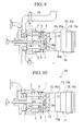
- FIG. 7 is a diagram showing a schematic cross-sectional view of a combustor according to another embodiment of the present invention provided with a water discharging device;
- FIG. 8 is a diagram showing a schematic cross-sectional view of a combustor according to yet another embodiment of the present invention provided with the water discharging device;
- FIG. 9 is a diagram showing a schematic cross-sectional view of a combustor according to yet another embodiment of the present invention provided with the water discharging device; and
- FIG. 10 is a diagram showing a schematic cross-sectional view of a conventional combustor for explaining a structure and elements thereof.
-
- The invention summarized above and defined by the enumerated claims may be better understood by referring to the following detailed description, which should be read with reference to the accompanying drawings. This detailed description of particular preferred embodiments, set out below to enable one to build and use particular implementations of the invention, is not intended to limit the enumerated claims, but to serve as particular examples thereof.
- Note that in the following figures, elements which are the same as the ones described in the prior art are enumerated using the same numerals and the explanation thereof is omitted.
- In FIG. 1, the numeral 21 indicates a pilot burner having a cooling water discharging function. In the
pilot burner 21, cooling water is discharged from apilot fuel nozzle 22 which is disposed at the end portion of thepilot burner 21 at the same time fuel is discharged. - Next, a structure of the
pilot fuel nozzle 22 will be described in detail. - As shown in FIGS. 2 and 3, a
fuel discharge outlet 23 is formed at the center of thepilot fuel nozzle 22 so that the fuel is discharged from thefuel discharge outlet 23. - An
annular flow path 24 is formed around thefuel discharge outlet 23 of thepilot fuel nozzle 22, and cooling water is transferred to theannular flow path 24 via a supply passage which is not shown in the figure. - Also, a plurality of
discharge openings 25 which communicate with theannular flow path 24 are formed at the end face of thepilot fuel nozzle 22 so that the cooling water introduced into theannular flow path 24 is discharged from thedischarge openings 25. - In this embodiment, the
discharge openings 25 include outercircumferential discharge openings 25a,central discharge openings 25b, and innercircumferential discharge openings 25c. The outercircumferential discharge openings 25a are formed toward the peripheral portion of thepilot fuel nozzle 22. Thecentral discharge openings 25b are formed along the axial direction of thenozzle 22, and the innercircumferential discharge openings 25c are formed toward the center of thenozzle 22. - Next, an explanation is made for discharging cooling water from the
discharge openings 25. - When cooling water is introduced in a state where the fuel is discharged from the
discharge outlet 23 at the center of thenozzle 22, the cooling water is discharged from each of thedischarge openings 25 into thecombustion chamber 10a. - As shown in FIG. 4, the cooling water discharged from the outer
circumferential discharge openings 25a is not affected by the fuel discharged from thedischarge outlet 23, and reaches a position at the inside of thecombustion chamber 10a further away from thepilot burner 21 and themain burner 1. - Also, as shown in FIG. 5, the cooling water discharged from the
central discharge openings 25b is slightly affected by the fuel discharged from thedischarge outlet 23 and the course of the cooling water is curved toward the periphery of thenozzle 22. Accordingly, the cooling water reaches a position at the inside of thecombustion chamber 10a closer to thepilot burner 21 and themain burner 1, as compared with the position of cooling water discharged from the outercircumferential discharge opening 25a. - Moreover, as shown in FIG. 6, the cooling water discharged from the inner
circumferential discharge openings 25c is most affected by the fuel discharged from thedischarge outlet 23 and the course of the cooling water curves strongly toward the periphery of thenozzle 22. Accordingly, the cooling water reaches a position at the inside of thecombustion chamber 10a closest to thepilot burner 21 and themain burner 1. - In this manner, it becomes possible to thoroughly spray the cooling water discharged from each of the
discharge openings 25 directly onto the first ring 15a, the second ring 15b, and the third ring 15c forming theheat chamber 11 shown in FIG. 1. - Note that although the directions of cooling water discharged from the
discharge openings 25 are varied by providing three different types of discharge openings, namely, the outercircumferential discharge openings 25a, thecentral discharge openings 25b, and the innercircumferential discharge openings 25c in the above embodiment, it is possible to change the discharging directions of cooling water by using swirling angles of thedischarge openings 25. - For example, if a discharge opening is formed towards inside with respect to an axial direction so as to have a large swirling angle taking into account envelopes, the cooling water is discharged in an inward direction at first and then changes to an outward. Accordingly, by changing combinations of the axial directions, swirling angles, etc., of the discharge openings, it becomes possible to design the discharging directions of cooling water so as to be suitable for a particular system used.
- As explained above, according to the
combustor 10 including thepilot fuel nozzle 22 having the above-mentioned structure, it becomes possible to cool down theheat chamber 11 reliably by spraying the cooling water onto the inside surfaces of theheat chamber 11 from thedischarge openings 25 which are provided around thefuel discharge outlet 23 disposed at the center of thepilot fuel nozzle 22 of thepilot burner 21. - Next, another embodiment according to the present invention will be explained with reference to FIGS. 7 through 9.
- In FIG. 7, the combustor is provided with a
water discharging device 16. Thewater discharging device 16 is disposed at the outside of the combustor and discharges water toward the outside surface of the combustor. Also, a part of the water discharged from thewater discharging device 16 is mixed in air used for cooling the surfaces of theheat chamber 11. Moreover, a part of the water discharged from thewater discharging device 16 is mixed with air used for combustion. In this manner, the temperature of gas and that of the surfaces of theheat chamber 11 are decreased and the output of the turbine may be increased. - In FIGS. 8 and 9, the
water discharging device 16 discharges water into air used for combustion so that the water is vaporized in the air to decrease the temperature of the gas. Also, a part of the water which is not vaporized flows along the swirling air flow and adheres to the surfaces of the combustor to decrease the temperature thereof. In this manner, the temperature of gas and that of the surfaces of theheat chamber 11 are decreased and the output of the turbine may be increased. - Accordingly, it becomes possible to prevent reliably heat from damaging the
heat chamber 11 due to an increase in the combustion temperature even if an amount of fuel is increased in order to increase the output of the system. Thus, the structures explained above are suitable, particularly, for theoil firing combustor 10 whose temperature at the downstream side of theheat chamber 11 tends to be increased, if cooling water is simply sprayed into thecombustion chamber 10, due to the difference in the vaporization speed between the fuel and the cooling water. - Also, since the direction of the
discharge openings 25 differs in the radial direction in accordance with the needs, the cooling water discharged from each of thedischarge openings 25 can be directed to various places of the inside surfaces of theheat chamber 11. Accordingly, it becomes possible to cool down theheat chamber 11 thoroughly. - More specifically, as mentioned above, since the
discharge openings 25 include the outercircumferential discharge openings 25a which are formed toward the peripheral portion of thepilot fuel nozzle 22, thecentral discharge openings 25b which are formed along the axial direction of thenozzle 22, and the innercircumferential discharge openings 25c which are formed toward the inside of thenozzle 22, the cooling water discharged from the outercircumferential discharge opening 25a is not affected by the fuel discharged from thedischarge outlet 23 at the center of thepilot fuel nozzle 22 of thepilot burner 21 and reaches positions at the inside of thecombustion chamber 10a further away from thepilot burner 21 and themain burner 1, the cooling water discharged from thecentral discharge opening 25b is more or less affected by the fuel discharged from thedischarge outlet 23 and the course of the cooling water curves toward the periphery of thenozzle 22 so that the cooling water reaches positions at the inside of thecombustion chamber 10a closer to thepilot burner 21 and themain burner 1, and the cooling water discharged from the innercircumferential discharge opening 25c is most affected by the fuel discharged from thedischarge outlet 23 and reaches positions at the inside of thecombustion chamber 10a closest to thepilot burner 21 and themain burner 1. Accordingly, it becomes possible to spray the cooling water, which is discharged from thedischarge openings 25, thoroughly onto the inside surfaces of theheat chamber 11 so that the heat damaging theheat chamber 11 may be reliably prevented. - As explained above, according to the present invention, the following effects may be obtained.
- According to a first aspect of the invention, since the cooling water is discharged from the discharge openings disposed around the fuel discharge outlet which is formed at the center of the nozzle and the cooling water is sprayed onto the inside surfaces of the heat chamber, it becomes possible to reliably cool down the heat chamber. For this reason, the heat damaging the heat chamber due to an increase in the combustion temperature may be reliably prevented even if an amount of fuel supplied is increased in order to increase the output of a turbine. Accordingly, this technique is suitable applied to an oil firing combustor whose temperature at the downstream side of the heat chamber is easily increased if cooling water is simply sprayed into the combustion chamber due the difference in the vaporization rate between the fuel and the cooling water.
- According to another aspect of the invention, since the directions of the cooling water discharged from the discharge openings differ in the radial direction, the cooling water may be directed to various places in the axial direction of the inside surfaces of the heat chamber. Accordingly, it becomes possible to thoroughly cool down the heat chamber.
- According to yet another aspect of the invention, since the discharge openings include the outer circumferential discharge openings which are formed toward the peripheral portion of the nozzle, the central discharge openings which are formed along the axial direction of the nozzle, and the inner circumferential discharge openings which are formed toward the inside of the nozzle, the cooling water discharged from the outer circumferential discharge opening is not affected by the fuel discharged from the discharge outlet at the center of the nozzle of the burner and reaches positions at the inside of the combustion chamber further away from the burner, the cooling water discharged from the central discharge opening is more or less affected by the fuel discharged from the discharge outlet and the course of the cooling water is curved toward the periphery of the nozzle so that the cooling water reaches positions at the inside of the combustion chamber closer to the burner, and the cooling water discharged from the inner circumferential discharge opening is most affected by the fuel discharged from the discharge outlet and reaches positions at the inside of the combustion chamber closest to the burner. Accordingly, it becomes possible to thoroughly spray the cooling water, which is discharged from the discharge openings, onto the inside surfaces of the heat chamber so that damage given to the heat chamber by heat may be reliably prevented.
- Having thus described example embodiments of the invention, it will be apparent that various alterations, modifications, and improvements will readily occur to those skilled in the art. Such alterations, modifications, and improvements, though not expressly described above, are nonetheless intended and implied to be within the spirit and scope of the invention. Accordingly, the foregoing discussion is intended to be illustrative only; the invention is limited and defined only by the following claims and equivalents thereto.
Claims (9)
- A combustor (10), comprising:a burner (21); anda combustion chamber (10a) including a heat chamber (11) to which fuel is supplied from said burner, whereinsaid burner includes a nozzle (22) having a fuel discharge outlet (23) from which the fuel is discharged into said combustion chamber; andsaid nozzle includes a plurality of discharge openings (25, 25a, 25b, 25c) around said fuel discharge outlet, from which cooling water is discharged toward inside surfaces of said heat chamber.
- A combustor as set forth in claim 1, wherein said fuel discharge outlet is formed at the center of said nozzle.
- A combustor as set forth in claim 1, wherein
said plurality of discharge openings are disposed so that the directions of the cooling water discharged from said discharge openings differ in the radial direction. - A combustor as set forth in claim 3, wherein
said plurality of discharge openings comprises an outer circumferential discharge opening (25a) which is formed toward the peripheral portion of said nozzle, a central discharge opening (25b) which is formed along the axial direction of said nozzle, and an inner circumferential discharge opening (25c) which is formed toward the center of said nozzle. - A combustor as set forth in claim 3, wherein the directions of the cooling water discharged from said discharge openings differ by using swirling angles of said discharge openings.
- A combustor according to any of the preceding claims, further comprising
a water discharging device (16) which discharges cooling water toward the outside surfaces of said combustor, said water discharging device being disposed at the outside of the combustor. - A combustor as set forth in claim 6, wherein
a part of the water discharged from said water discharging device is mixed in air used for cooling the surfaces of said heat chamber, and a part of the water discharged from said water discharging device is mixed with air used for combustion so that the temperature of gas and that of the surfaces of said heat chamber may be decreased. - A combustor as set forth in claim 6, wherein
said water discharging device discharges water into air used for combustion so that the water is vaporized in the air to decrease the temperature of gas, and a part of the water which is not vaporized flows along a swirling air flow to be adheres to surfaces of said combustor to decrease the temperature thereof. - A combustor according to any of the preceding claims,
wherein said combustor is an oil firing combustor.
Applications Claiming Priority (2)
| Application Number | Priority Date | Filing Date | Title |
|---|---|---|---|
| JP2000351027 | 2000-11-17 | ||
| JP2000351027A JP2002156115A (en) | 2000-11-17 | 2000-11-17 | Combustor |
Publications (3)
| Publication Number | Publication Date |
|---|---|
| EP1207344A2 true EP1207344A2 (en) | 2002-05-22 |
| EP1207344A3 EP1207344A3 (en) | 2003-04-02 |
| EP1207344B1 EP1207344B1 (en) | 2007-01-10 |
Family
ID=18824153
Family Applications (1)
| Application Number | Title | Priority Date | Filing Date |
|---|---|---|---|
| EP01126536A Expired - Lifetime EP1207344B1 (en) | 2000-11-17 | 2001-11-14 | Combustor |
Country Status (5)
| Country | Link |
|---|---|
| US (1) | US6662547B2 (en) |
| EP (1) | EP1207344B1 (en) |
| JP (1) | JP2002156115A (en) |
| CA (1) | CA2361962C (en) |
| DE (1) | DE60125892T2 (en) |
Cited By (3)
| Publication number | Priority date | Publication date | Assignee | Title |
|---|---|---|---|---|
| US7694521B2 (en) | 2004-03-03 | 2010-04-13 | Mitsubishi Heavy Industries, Ltd. | Installation structure of pilot nozzle of combustor |
| EP2188570A4 (en) * | 2007-09-13 | 2015-11-11 | Maxon Corp | Burner apparatus |
| EP3076077A4 (en) * | 2013-11-29 | 2017-07-12 | Mitsubishi Hitachi Power Systems, Ltd. | Nozzle, combustion apparatus, and gas turbine |
Families Citing this family (13)
| Publication number | Priority date | Publication date | Assignee | Title |
|---|---|---|---|---|
| JP3986348B2 (en) * | 2001-06-29 | 2007-10-03 | 三菱重工業株式会社 | Fuel supply nozzle of gas turbine combustor, gas turbine combustor, and gas turbine |
| US7065955B2 (en) * | 2003-06-18 | 2006-06-27 | General Electric Company | Methods and apparatus for injecting cleaning fluids into combustors |
| CN102261270A (en) * | 2010-05-25 | 2011-11-30 | 谢海洋 | High-efficiency gas-steam combined type turbine engine |
| US20110314831A1 (en) * | 2010-06-23 | 2011-12-29 | Abou-Jaoude Khalil F | Secondary water injection for diffusion combustion systems |
| JP5631223B2 (en) * | 2011-01-14 | 2014-11-26 | 三菱重工業株式会社 | Fuel nozzle, gas turbine combustor including the same, and gas turbine including the same |
| US9243803B2 (en) | 2011-10-06 | 2016-01-26 | General Electric Company | System for cooling a multi-tube fuel nozzle |
| US9709271B2 (en) | 2013-02-20 | 2017-07-18 | Fluor Technologies Corporation | Thermally controlled combustion system |
| WO2014130027A1 (en) * | 2013-02-20 | 2014-08-28 | Fluor Technologies Corporation | Thermally controlled combustion system |
| US9958152B2 (en) | 2014-08-14 | 2018-05-01 | Siemens Aktiengesellschaft | Multi-functional fuel nozzle with an atomizer array |
| EP3180565B1 (en) | 2014-08-14 | 2019-04-17 | Siemens Aktiengesellschaft | Multi-functional fuel nozzle with a dual-orifice atomizer |
| US10837642B2 (en) | 2015-07-03 | 2020-11-17 | Mitsubishi Hitachi Power Systems, Ltd. | Combustor nozzle, gas turbine combustor, gas turbine, cover ring, and combustor nozzle manufacturing method |
| US10371048B2 (en) * | 2016-02-22 | 2019-08-06 | Mitsubishi Hitachi Power Systems, Ltd. | Combustor and gas turbine |
| KR101932857B1 (en) * | 2017-08-31 | 2018-12-31 | 한국전력공사 | Control Device and Control Method for Gas Turbine |
Citations (6)
| Publication number | Priority date | Publication date | Assignee | Title |
|---|---|---|---|---|
| GB644719A (en) * | 1947-05-14 | 1950-10-18 | Bataafsche Petroleum | Method of and apparatus for temporarily increasing the output of propulsive gases from a combustion chamber |
| US4425755A (en) * | 1980-09-16 | 1984-01-17 | Rolls-Royce Limited | Gas turbine dual fuel burners |
| EP0314112A1 (en) * | 1987-10-27 | 1989-05-03 | Kabushiki Kaisha Toshiba | Combustor for gas turbine |
| US5224851A (en) * | 1992-05-08 | 1993-07-06 | Shell Oil Company | Low NOx burner |
| US5408830A (en) * | 1994-02-10 | 1995-04-25 | General Electric Company | Multi-stage fuel nozzle for reducing combustion instabilities in low NOX gas turbines |
| US5690039A (en) * | 1996-06-17 | 1997-11-25 | Rjm Corporation | Method and apparatus for reducing nitrogen oxides using spatially selective cooling |
Family Cites Families (9)
| Publication number | Priority date | Publication date | Assignee | Title |
|---|---|---|---|---|
| US2168313A (en) * | 1936-08-28 | 1939-08-08 | Bichowsky Francis Russell | Combustion means |
| US2453378A (en) * | 1941-11-07 | 1948-11-09 | Asiatic Petroleum Co Ltd | Liquid-cooled nozzle arrangement for combustion chambers of jet propulsion apparatus |
| US3747336A (en) * | 1972-03-29 | 1973-07-24 | Gen Electric | Steam injection system for a gas turbine |
| JPS5239007A (en) * | 1975-09-22 | 1977-03-26 | Hitachi Ltd | Combustor used for a gas turbine |
| JPS59203826A (en) | 1983-05-04 | 1984-11-19 | Hitachi Ltd | Liner for gas-turbine combustor |
| US4533314A (en) * | 1983-11-03 | 1985-08-06 | General Electric Company | Method for reducing nitric oxide emissions from a gaseous fuel combustor |
| JPS60149828A (en) * | 1984-01-13 | 1985-08-07 | Hitachi Ltd | Combustion device |
| JP3174634B2 (en) * | 1992-08-11 | 2001-06-11 | 三菱重工業株式会社 | Gas turbine fuel injection system |
| JP4246874B2 (en) * | 2000-03-10 | 2009-04-02 | 三菱重工業株式会社 | Multifunctional water injection manifold and operation method thereof |
-
2000
- 2000-11-17 JP JP2000351027A patent/JP2002156115A/en active Pending
-
2001
- 2001-11-14 EP EP01126536A patent/EP1207344B1/en not_active Expired - Lifetime
- 2001-11-14 DE DE60125892T patent/DE60125892T2/en not_active Expired - Fee Related
- 2001-11-14 CA CA002361962A patent/CA2361962C/en not_active Expired - Fee Related
- 2001-11-15 US US09/987,519 patent/US6662547B2/en not_active Expired - Lifetime
Patent Citations (6)
| Publication number | Priority date | Publication date | Assignee | Title |
|---|---|---|---|---|
| GB644719A (en) * | 1947-05-14 | 1950-10-18 | Bataafsche Petroleum | Method of and apparatus for temporarily increasing the output of propulsive gases from a combustion chamber |
| US4425755A (en) * | 1980-09-16 | 1984-01-17 | Rolls-Royce Limited | Gas turbine dual fuel burners |
| EP0314112A1 (en) * | 1987-10-27 | 1989-05-03 | Kabushiki Kaisha Toshiba | Combustor for gas turbine |
| US5224851A (en) * | 1992-05-08 | 1993-07-06 | Shell Oil Company | Low NOx burner |
| US5408830A (en) * | 1994-02-10 | 1995-04-25 | General Electric Company | Multi-stage fuel nozzle for reducing combustion instabilities in low NOX gas turbines |
| US5690039A (en) * | 1996-06-17 | 1997-11-25 | Rjm Corporation | Method and apparatus for reducing nitrogen oxides using spatially selective cooling |
Cited By (5)
| Publication number | Priority date | Publication date | Assignee | Title |
|---|---|---|---|---|
| US7694521B2 (en) | 2004-03-03 | 2010-04-13 | Mitsubishi Heavy Industries, Ltd. | Installation structure of pilot nozzle of combustor |
| DE112004002704B4 (en) * | 2004-03-03 | 2011-04-07 | Mitsubishi Heavy Industries, Ltd. | incinerator |
| EP2188570A4 (en) * | 2007-09-13 | 2015-11-11 | Maxon Corp | Burner apparatus |
| EP3076077A4 (en) * | 2013-11-29 | 2017-07-12 | Mitsubishi Hitachi Power Systems, Ltd. | Nozzle, combustion apparatus, and gas turbine |
| US10570820B2 (en) | 2013-11-29 | 2020-02-25 | Mitsubishi Hitachi Power Systems, Ltd. | Nozzle, combustion apparatus, and gas turbine |
Also Published As
| Publication number | Publication date |
|---|---|
| DE60125892T2 (en) | 2007-10-25 |
| CA2361962C (en) | 2008-02-19 |
| JP2002156115A (en) | 2002-05-31 |
| US20020061485A1 (en) | 2002-05-23 |
| CA2361962A1 (en) | 2002-05-17 |
| EP1207344A3 (en) | 2003-04-02 |
| DE60125892D1 (en) | 2007-02-22 |
| EP1207344B1 (en) | 2007-01-10 |
| US6662547B2 (en) | 2003-12-16 |
Similar Documents
| Publication | Publication Date | Title |
|---|---|---|
| US6662547B2 (en) | Combustor | |
| US8656699B2 (en) | Combustion burner | |
| US4991398A (en) | Combustor fuel nozzle arrangement | |
| CN1707080B (en) | Methods and apparatus for low emission gas turbine energy generation | |
| JP2839777B2 (en) | Fuel injection nozzle for gas turbine combustor | |
| KR100247097B1 (en) | Single stage dual mode combustor for gas turbine | |
| US5289685A (en) | Fuel supply system for a gas turbine engine | |
| CN102330978B (en) | Flame tolerant secondary fuel nozzle | |
| US6374615B1 (en) | Low cost, low emissions natural gas combustor | |
| US7891191B2 (en) | Combustor, gas turbine combustor, and air supply method for same | |
| US8607571B2 (en) | Lean burn injectors having a main fuel circuit and one of multiple pilot fuel circuits with prefiliming air-blast atomizers | |
| EP0692083B1 (en) | Injector having low tip temperature | |
| US6189314B1 (en) | Premix combustor for gas turbine engine | |
| JP5591408B2 (en) | Low calorific value fuel combustor for gas turbines. | |
| US6834506B2 (en) | Main liquid fuel injection device for a single combustion chamber, having a premixing chamber, of a gas turbine with low emission of pollutants | |
| JPH06235519A (en) | Combustion apparatus for gas turbine | |
| US20050016177A1 (en) | Improved combination of a premixing chamber and a combustion chamber, with low emission of pollutants, for gas turbines running on liquid and/or gas fuel | |
| CN103930723A (en) | Tangential annular combustor with premixed fuel and air for use on gas turbine engines | |
| US20030051480A1 (en) | Fuel nozzle producing skewed spray pattern | |
| EP0831275B1 (en) | Annular type gas turbine combustor | |
| WO1990000677A1 (en) | Assuring reliable starting of turbine engines | |
| JP2004012039A (en) | Gas turbine combustor | |
| US20200018232A1 (en) | Independently controlled three stage water injection in a diffusion burner | |
| JP2886844B2 (en) | Gas turbine with premixed combustor | |
| JP2000314526A (en) | Pre-evaporation/premixing burner and premixing burner for gas turbine combustor |
Legal Events
| Date | Code | Title | Description |
|---|---|---|---|
| PUAI | Public reference made under article 153(3) epc to a published international application that has entered the european phase |
Free format text: ORIGINAL CODE: 0009012 |
|
| 17P | Request for examination filed |
Effective date: 20011114 |
|
| AX | Request for extension of the european patent |
Free format text: AL;LT;LV;MK;RO;SI |
|
| PUAL | Search report despatched |
Free format text: ORIGINAL CODE: 0009013 |
|
| AK | Designated contracting states |
Kind code of ref document: A3 Designated state(s): AT BE CH CY DE DK ES FI FR GB GR IE IT LI LU MC NL PT SE TR |
|
| AX | Request for extension of the european patent |
Extension state: AL LT LV MK RO SI |
|
| AKX | Designation fees paid |
Designated state(s): CH DE FR GB IT LI |
|
| GRAP | Despatch of communication of intention to grant a patent |
Free format text: ORIGINAL CODE: EPIDOSNIGR1 |
|
| GRAS | Grant fee paid |
Free format text: ORIGINAL CODE: EPIDOSNIGR3 |
|
| GRAA | (expected) grant |
Free format text: ORIGINAL CODE: 0009210 |
|
| AK | Designated contracting states |
Kind code of ref document: B1 Designated state(s): CH DE FR GB IT LI |
|
| PG25 | Lapsed in a contracting state [announced via postgrant information from national office to epo] |
Ref country code: CH Free format text: LAPSE BECAUSE OF FAILURE TO SUBMIT A TRANSLATION OF THE DESCRIPTION OR TO PAY THE FEE WITHIN THE PRESCRIBED TIME-LIMIT Effective date: 20070110 Ref country code: LI Free format text: LAPSE BECAUSE OF FAILURE TO SUBMIT A TRANSLATION OF THE DESCRIPTION OR TO PAY THE FEE WITHIN THE PRESCRIBED TIME-LIMIT Effective date: 20070110 |
|
| REG | Reference to a national code |
Ref country code: GB Ref legal event code: FG4D |
|
| REF | Corresponds to: |
Ref document number: 60125892 Country of ref document: DE Date of ref document: 20070222 Kind code of ref document: P |
|
| REG | Reference to a national code |
Ref country code: CH Ref legal event code: PL |
|
| EN | Fr: translation not filed | ||
| PLBE | No opposition filed within time limit |
Free format text: ORIGINAL CODE: 0009261 |
|
| STAA | Information on the status of an ep patent application or granted ep patent |
Free format text: STATUS: NO OPPOSITION FILED WITHIN TIME LIMIT |
|
| 26N | No opposition filed |
Effective date: 20071011 |
|
| PG25 | Lapsed in a contracting state [announced via postgrant information from national office to epo] |
Ref country code: IT Free format text: LAPSE BECAUSE OF FAILURE TO SUBMIT A TRANSLATION OF THE DESCRIPTION OR TO PAY THE FEE WITHIN THE PRESCRIBED TIME-LIMIT Effective date: 20070110 Ref country code: FR Free format text: LAPSE BECAUSE OF FAILURE TO SUBMIT A TRANSLATION OF THE DESCRIPTION OR TO PAY THE FEE WITHIN THE PRESCRIBED TIME-LIMIT Effective date: 20070831 |
|
| GBPC | Gb: european patent ceased through non-payment of renewal fee |
Effective date: 20071114 |
|
| PG25 | Lapsed in a contracting state [announced via postgrant information from national office to epo] |
Ref country code: FR Free format text: LAPSE BECAUSE OF FAILURE TO SUBMIT A TRANSLATION OF THE DESCRIPTION OR TO PAY THE FEE WITHIN THE PRESCRIBED TIME-LIMIT Effective date: 20070110 |
|
| PG25 | Lapsed in a contracting state [announced via postgrant information from national office to epo] |
Ref country code: GB Free format text: LAPSE BECAUSE OF NON-PAYMENT OF DUE FEES Effective date: 20071114 |
|
| PGFP | Annual fee paid to national office [announced via postgrant information from national office to epo] |
Ref country code: DE Payment date: 20081107 Year of fee payment: 8 |
|
| PG25 | Lapsed in a contracting state [announced via postgrant information from national office to epo] |
Ref country code: DE Free format text: LAPSE BECAUSE OF NON-PAYMENT OF DUE FEES Effective date: 20100601 |