EP1206997A2 - Laser machining device with observation system - Google Patents
Laser machining device with observation system Download PDFInfo
- Publication number
- EP1206997A2 EP1206997A2 EP01127214A EP01127214A EP1206997A2 EP 1206997 A2 EP1206997 A2 EP 1206997A2 EP 01127214 A EP01127214 A EP 01127214A EP 01127214 A EP01127214 A EP 01127214A EP 1206997 A2 EP1206997 A2 EP 1206997A2
- Authority
- EP
- European Patent Office
- Prior art keywords
- laser beam
- laser
- focusing unit
- mirror
- workpiece
- Prior art date
- Legal status (The legal status is an assumption and is not a legal conclusion. Google has not performed a legal analysis and makes no representation as to the accuracy of the status listed.)
- Granted
Links
Images
Classifications
-
- B—PERFORMING OPERATIONS; TRANSPORTING
- B23—MACHINE TOOLS; METAL-WORKING NOT OTHERWISE PROVIDED FOR
- B23K—SOLDERING OR UNSOLDERING; WELDING; CLADDING OR PLATING BY SOLDERING OR WELDING; CUTTING BY APPLYING HEAT LOCALLY, e.g. FLAME CUTTING; WORKING BY LASER BEAM
- B23K26/00—Working by laser beam, e.g. welding, cutting or boring
- B23K26/02—Positioning or observing the workpiece, e.g. with respect to the point of impact; Aligning, aiming or focusing the laser beam
- B23K26/03—Observing, e.g. monitoring, the workpiece
- B23K26/032—Observing, e.g. monitoring, the workpiece using optical means
Definitions
- the invention relates to a laser processing device, in particular a laser welding device with an observation device to observe the working point.
- DE 38 07 471 A1 describes a device for guiding a Laser beam known in which the laser beam with a pivotable deflecting mirror around two mutually perpendicular axes can be swiveled around when processing non-planes Workpieces with a correct alignment of the angle to which the laser beam hits the workpiece. In this way, the direction of propagation of the laser beam at the respective working point perpendicular to the surface of the workpiece are aligned without this entire workpiece must be pivoted.
- the use of a optical aids to check the correct positioning of the laser beam on the workpiece is in the known However, the device is not provided.
- a laser processing device with an observation microscope is known for example from US 5,449,882 A.
- This Laser processing device is behind a dichroic mirror a fixed observation microscope arranged that an observation of the workpiece in the working area of the laser beam allows.
- Using a fixed microscope is sufficient because this is just a linear shift of the laser beam in one allows relatively small work area, so the focus the fixed field of view of the observation microscope does not leave.
- the location of the focus of the laser beam is also only recognizable if this on the Workpiece hits, so that a correction of the focus position can only be done after the start of processing.
- the invention is based on the object, a laser processing device, in particular to specify a laser welding device, that with a compact structure and with a relatively large, from Laser beam detectable work area precise positioning and alignment of the laser beam on the workpiece enabled before the start of editing.
- a dichroic Mirror is arranged to which an observation device such is assigned that their optical axis with the axis seen in the direction of propagation of the laser beam laser beam propagating behind or behind the dichroic mirror coincides is correct and precise positioning of the workpiece in the working point and alignment of the laser beam possible.
- an observation device such is assigned that their optical axis with the axis seen in the direction of propagation of the laser beam laser beam propagating behind or behind the dichroic mirror coincides is correct and precise positioning of the workpiece in the working point and alignment of the laser beam possible.
- Through entanglement or overlay the beam path of the laser beam and the observation device ensures that the focus of the laser beam, i.e. the correct working point, even with a Always change the orientation of the laser beam in the Middle of the field of view of the observation device, for example congruent with a displayed crosshair, lies.
- the middle of the field of view automatically and automatically gives the point of impact of the Laser beam on the workpiece again.
- the correct position of the workpiece is given when the selected working point on the workpiece surface in the observation device is centered and in focus.
- the position of the focus can thus be exactly the desired working point can be set.
- the dichroic mirror in front of the pivotable focusing unit, i.e. in the section of the Beam path of the laser beam from the laser beam source to Focusing unit inside the laser processing device is spatially fixed, the swiveling laser beam observed with a fixed observation device be, which can be detected by the pivoting movement
- Working area of the laser beam can be larger than that Field of vision of the observation device. Because the visual field the observation device automatically and inevitably the Panning movement of the laser beam follows, depending on the application can be worked with relatively high magnifications.
- the laser processing device comprises a laser beam source 2, for example an Nd: YAG solid-state laser, which generates a laser beam LS.
- a laser beam source 2 for example an Nd: YAG solid-state laser
- the laser beam LS In the beam path of the laser beam LS is a dichroic (wavelength selective) Arranged mirror 4, which reflects the laser beam LS, so that this via a further deflecting mirror 6 to a pivotable focusing unit 8 is deflected, the laser beam LS focused.
- the beam path of the laser beam LS between the focusing unit 8 and the laser beam source 2 is spatially within the laser processing device established.
- the pivotable focusing unit contains 8 a deflecting mirror 82 and an optically downstream one Focusing optics 84, in the exemplary embodiment a lens, with which the laser beam LS focuses on a workpiece WS becomes.
- the workpiece WS is in for correct positioning a starting position required for laser processing and for the relative movement between the laser beam LS and Workpiece WS during machining on a height adjustable Cross table arranged in the figure by an axis cross 10 is only shown symbolically.
- the pivotable focusing unit 8 is gimbal-suspended and can be pivoted about two axes of rotation, in the exemplary embodiment about two axes of rotation x, y orthogonal to one another, so that the focused laser beam LS can be pivoted about the angles of rotation ⁇ x , ⁇ y .
- One of the axes of rotation x, y, in the exemplary embodiment the axis of rotation x, coincides with the axis of the laser beam LS propagating from the deflection mirror 6 to the focusing unit 8.
- the axis of rotation y is perpendicular to this.
- the axes of rotation x, y intersect at a common intersection S, which is also the point of incidence of the laser beam LS on the deflecting mirror 82.
- a pivoting movement of the focusing unit 8 causes a pivoting movement of the laser beam LS in the working plane through the angles ⁇ x , ⁇ y . So that the laser beam LS follows the pivoting movement of the focusing unit 8 about the axis of rotation y, it is necessary to tilt the deflecting mirror 82 accordingly by the angle ⁇ y / 2. The deflecting mirror 82 must therefore be tilted about the axis of rotation y by an angle which is half as large as the pivoting angle ⁇ y of the focusing unit 8.
- the deflecting mirror 82 is therefore relative to the focusing unit 8 about the axis of rotation y and thus relative to the fixedly installed focusing optics 84 are rotatably mounted within the focusing unit 8. This is illustrated in the figure by the pivot bearing 86 shown schematically.
- Behind the dichroic mirror 4 is a fixed binocular Observing microscope 20 arranged such that whose optical axis 22 with that within the laser processing device fixed optical axis 24 of the dichroic Mirror 4 deflected, d. H. of the spreading direction of the laser beam LS seen behind or behind the dichroic mirror 4 propagating laser beam LS coincides.
- the dichroic mirror 4 is in the embodiment trained such that it has light in the area the wavelength of the laser beam LS, 1064nm in the example, is reflected and lets light through in the visible wavelength range, so using the binocular observation microscope 20 the workpiece WS in the area of the focus or working point A of the laser beam LS can be observed.
- the Beam path of the laser beam LS with the beam path of the observation microscope 20 coincides, it is ensured that with a pivoting movement of the focusing unit 8 with the Deflecting mirror 82 and the focusing optics 84 the middle of the field of view F of the observation microscope 20, which is preferably is marked by a crosshair, and the Focus area (object plane that is in focus) always coincides with the working point A.
- the working point A is then correctly in the focus of the laser beam LS positioned when in the middle of the field of view F of the observation microscope 20 is in focus is.
- the focusing unit 8 is pivoted about the axes of rotation x, y manually in order to enable an individual setting of the angle of incidence and point of incidence of the laser beam LS on the workpiece WS.
- the deflecting mirror 82 automatically follows the pivoting movement of the focusing unit 8 by the respectively correct angle, x , ⁇ y / 2.
- transparent dichroic mirror for light in the visible Wavelength range of transparent dichroic mirror is basically the use of a dichroic Possible mirror that transmits the laser light and Light reflected in the visible wavelength range.
- a fixed binocular observation microscope a fixed video camera is also provided be, which enables remote control of the swivel optics.
Abstract
Description
Die Erfindung bezieht sich auf ein Laserbearbeitungsgerät, insbesondere ein Laserschweißgerät, mit einer Beobachtungseinrichtung zum Beobachten des Arbeitspunktes.The invention relates to a laser processing device, in particular a laser welding device with an observation device to observe the working point.
Bei der Bearbeitung eines Werkstückes mit einem Laserstrahl ist es erforderlich, den jeweiligen Arbeitspunkt am Werkstück korrekt im Fokus des von einer Fokussiereinheit fokussierten Laserstrahls anzuordnen. Insbesondere bei der manuellen Feinbearbeitung eines Werkstückes mit einem sogenannten Handschweißlasergerät, beispielsweise bei der Nachbearbeitung von Spritzgussformen durch Auftragsschweißen, wird zur korrekten Einstellung des Fokus und des Auftreffpunktes des Laserstrahles auf dem Werkstück ein Beobachtungsmikroskop verwendet. Die korrekte Positionierung des Werkstücks wird mit Hilfe eines höhenverstellbaren x-y-Tisches vorgenommen. Um auch Kanten bearbeiten zu können oder Arbeitspunkte auf Werkstückflächen zu erreichen, die senkrecht zur x-y-Ebene orientiert sind, muss auch die Ausbreitungsrichtung des fokussierten Laserstrahls relativ zum Werkstück, d. h. der Winkel, unter dem der Laserstrahl auf das Werkstück auftrifft, der jeweiligen Lage des Arbeitspunktes angepasst werden, so dass es zusätzlich erforderlich sein kann, das Werkstück relativ zur Fokussiereinheit zu verkippen.When processing a workpiece with a laser beam it is necessary to determine the respective working point on the workpiece correctly in the focus of that focused by a focusing unit Arrange laser beam. Especially with manual finishing a workpiece with a so-called manual welding laser device, for example when postprocessing Injection molding by cladding becomes the correct one Setting the focus and the point of impact of the laser beam an observation microscope is used on the workpiece. The correct positioning of the workpiece is checked using a height-adjustable x-y table. Around edges too to be able to edit or work points on workpiece surfaces to achieve that is oriented perpendicular to the x-y plane the direction of propagation of the focused laser beam relative to the workpiece, d. H. the angle at which the laser beam hits the workpiece, the respective one Position of the working point can be adjusted so that it is additional may be necessary, the workpiece relative to the focusing unit to tilt.
Aus der DE 38 07 471 A1 ist eine Vorrichtung zum Führen eines Laserstrahles bekannt, bei der der Laserstrahl mit einem schwenkbaren Umlenkspiegel um zwei zueinander senkrechte Achsen geschwenkt werden kann, um bei der Bearbeitung von nichtebenen Werkstücken eine korrekte Ausrichtung des Winkels, mit dem der Laserstrahl auf das Werkstück auftrifft, zu ermöglichen. Auf diese Weise kann die Ausbreitungsrichtung des Laserstrahls im jeweiligen Arbeitspunkt senkrecht zur Oberfläche des Werkstücks ausgerichtet werden, ohne dass hierzu das gesamte Werkstück geschwenkt werden muss. Die Verwendung eines optischen Hilfsmittels zur Kontrolle der korrekten Positionierung des Laserstrahls auf dem Werkstück ist bei der bekannten Vorrichtung jedoch nicht vorgesehen.DE 38 07 471 A1 describes a device for guiding a Laser beam known in which the laser beam with a pivotable deflecting mirror around two mutually perpendicular axes can be swiveled around when processing non-planes Workpieces with a correct alignment of the angle to which the laser beam hits the workpiece. In this way, the direction of propagation of the laser beam at the respective working point perpendicular to the surface of the workpiece are aligned without this entire workpiece must be pivoted. The use of a optical aids to check the correct positioning of the laser beam on the workpiece is in the known However, the device is not provided.
Ein Laserbearbeitungsgerät mit einem Beobachtungsmikroskop ist beispielsweise aus der US 5,449,882 A bekannt. Bei diesem Laserbearbeitungsgerät ist hinter einem dichroitischen Spiegel ein feststehendes Beobachtungsmikroskop angeordnet, das eine Beobachtung des Werkstückes im Arbeitsbereich des Laserstrahls ermöglicht. Bei der bekannten Vorrichtung ist die Verwendung eines feststehenden Mikroskops ausreichend, da diese nur eine Linearverschiebung des Laserstrahls in einem relativ kleinen Arbeitsbereich ermöglicht, so dass der Fokus des Laserstrahls das feststehende Gesichtsfeld des Beobachtungsmikroskops nicht verlässt. Die Lage des Fokus des Laserstrahls ist außerdem erst dann erkennbar, wenn dieser auf das Werkstück auftrifft, so dass eine Korrektur der Fokuslage erst nach dem Beginn der Bearbeitung erfolgen kann.A laser processing device with an observation microscope is known for example from US 5,449,882 A. With this Laser processing device is behind a dichroic mirror a fixed observation microscope arranged that an observation of the workpiece in the working area of the laser beam allows. In the known device Using a fixed microscope is sufficient because this is just a linear shift of the laser beam in one allows relatively small work area, so the focus the fixed field of view of the observation microscope does not leave. The location of the focus of the laser beam is also only recognizable if this on the Workpiece hits, so that a correction of the focus position can only be done after the start of processing.
Der Erfindung liegt nun die Aufgabe zugrunde, ein Laserbearbeitungsgerät, insbesondere ein Laserschweißgerät, anzugeben, das bei kompaktem Aufbau und mit einem relativ großen, vom Laserstrahl erfassbaren Arbeitsbereich eine präzise Positionierung und Ausrichtung des Laserstrahls auf das Werkstück noch vor dem Beginn der Bearbeitung ermöglicht.The invention is based on the object, a laser processing device, in particular to specify a laser welding device, that with a compact structure and with a relatively large, from Laser beam detectable work area precise positioning and alignment of the laser beam on the workpiece enabled before the start of editing.
Die genannte Aufgabe wird gemäß der Erfindung gelöst mit einem Laserbearbeitungsgerät mit den Merkmalen des Patentanspruches 1.The stated object is achieved according to the invention with a Laser processing device with the features of the claim 1.
Da eine schwenkbare Fokussiereinheit vorgesehen ist, ist in einer Vielzahl von Anwendungsfällen ein Verkippen oder Schwenken des Werkstückes nicht mehr erforderlich. Vielmehr erfolgt die Ausrichtung des Laserstrahls durch Schwenken der Fokussiereinheit, die aufgrund der geringen bewegten Massen mechanisch unaufwendiger und präziser positioniert werden kann. Durch die Verwendung einer schwenkbaren Fokussiereinheit kann außerdem mit einer kleinen Fokussierlinse oder einem kleinen Fokussierspiegel ein großer Ablenkwinkel verwirklicht werden.Since a pivotable focusing unit is provided, in a tilting or a variety of applications Swiveling of the workpiece is no longer necessary. Much more the laser beam is aligned by swiveling the Focusing unit due to the small moving masses be positioned mechanically less complex and more precise can. By using a swiveling focusing unit can also be used with a small focusing lens or a small focusing mirror realizes a large deflection angle become.
Da außerdem im Strahlengang des Laserstrahls zwischen der Laserstrahlquelle und der Fokussiereinheit ein dichroitischer Spiegel angeordnet ist, dem eine Beobachtungseinrichtung derart zugeordnet ist, dass deren optische Achse mit der Achse des sich in Ausbreitungsrichtung des Laserstrahls gesehen nach oder hinter dem dichroitischen Spiegel ausbreitenden Laserstrahls zusammenfällt, ist eine korrekte und präzise Positionierung des Werkstückes im Arbeitspunkt und Ausrichtung des Laserstrahls möglich. Durch die Verschränkung oder Überlagerung des Strahlenganges des Laserstrahls und der Beobachtungseinrichtung ist sichergestellt, dass der Fokus des Laserstrahls, d.h. der korrekte Arbeitspunkt, auch bei einer Veränderung der Ausrichtung des Laserstrahls stets in der Mitte des Gesichtsfeldes der Beobachtungseinrichtung, beispielsweise deckungsgleich mit einem eingeblendeten Fadenkreuz, liegt. Mit anderen Worten: Die Mitte des Gesichtsfeldes gibt zwangsläufig und automatisch den Auftreffpunkt des Laserstrahls auf dem Werkstück wieder. Die korrekte Position des Werkstückes ist dann gegeben, wenn der angewählte Arbeitspunkt auf der Werkstückoberfläche in der Beobachtungseinrichtung mittig und scharf eingestellt ist. Bereits vor dem Beginn der Bearbeitung, d. h. vor dem Einschalten der Laserstrahlquelle kann somit die Position des Fokus exakt auf den gewünschten Arbeitspunkt eingestellt werden. Since also in the beam path of the laser beam between the laser beam source and the focusing unit is a dichroic Mirror is arranged to which an observation device such is assigned that their optical axis with the axis seen in the direction of propagation of the laser beam laser beam propagating behind or behind the dichroic mirror coincides is correct and precise positioning of the workpiece in the working point and alignment of the laser beam possible. Through entanglement or overlay the beam path of the laser beam and the observation device ensures that the focus of the laser beam, i.e. the correct working point, even with a Always change the orientation of the laser beam in the Middle of the field of view of the observation device, for example congruent with a displayed crosshair, lies. In other words, the middle of the field of view automatically and automatically gives the point of impact of the Laser beam on the workpiece again. The correct position of the workpiece is given when the selected working point on the workpiece surface in the observation device is centered and in focus. Already before the start of processing, d. H. before switching on the laser beam source the position of the focus can thus be exactly the desired working point can be set.
Durch die Anordnung des dichroitischen Spiegels vor der schwenkbaren Fokussiereinheit, also in dem Abschnitt des Strahlenganges des Laserstrahls von der Laserstrahlquelle zur Fokussiereinheit, der innerhalb des Laserbearbeitungsgerätes räumlich feststehend ist, kann der schwenkbare Laserstrahl mit einer ebenfalls feststehenden Beobachtungseinrichtung beobachtet werden, wobei der durch die Schwenkbewegung erfassbare Arbeitsbereich des Laserstrahls größer sein kann als das Gesichtsfeld der Beobachtungseinrichtung. Da das Gesichtsfeld der Beobachtungseinrichtung automatisch und zwangsläufig der Schwenkbewegung des Laserstrahls folgt, kann je nach Anwendungsfall mit relativ hohen Vergrößerungen gearbeitet werden.By arranging the dichroic mirror in front of the pivotable focusing unit, i.e. in the section of the Beam path of the laser beam from the laser beam source to Focusing unit inside the laser processing device is spatially fixed, the swiveling laser beam observed with a fixed observation device be, which can be detected by the pivoting movement Working area of the laser beam can be larger than that Field of vision of the observation device. Because the visual field the observation device automatically and inevitably the Panning movement of the laser beam follows, depending on the application can be worked with relatively high magnifications.
Weitere vorteilhafte Ausgestaltungen der Erfindung ergeben sich gemäß der Unteransprüche.Further advantageous embodiments of the invention result themselves according to the subclaims.
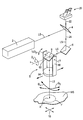
Zur weiteren Erläuterungen der Erfindung wird auf das Ausführungsbeispiel der Zeichnung verwiesen, deren einzige Figur ein erfindungsgemäßes Laserbearbeitungsgerät in einer schematischen perspektivischen Darstellung zeigt.To further explain the invention, reference is made to the embodiment referred to the drawing, its only figure an inventive laser processing device in a schematic shows perspective view.
Gemäß der Figur umfasst das Laserbearbeitungsgerät eine Laserstrahlquelle
2, beispielsweise ein Nd:YAG-Festkörperlaser,
die einen Laserstrahl LS erzeugt. Im Strahlengang des Laserstrahls
LS ist ein dichroitischer (wellenlängenselektiver)
Spiegel 4 angeordnet, der den Laserstrahl LS reflektiert, so
dass dieser über einen weiteren Umlenkspiegel 6 zu einer
schwenkbaren Fokussiereinheit 8 umgelenkt wird, die den Laserstrahl
LS fokussiert. Der Strahlengang des Laserstrahles
LS zwischen der Fokussiereinheit 8 und der Laserstrahlquelle
2 ist innerhalb des Laserbearbeitungsgerätes räumlich
festgelegt.According to the figure, the laser processing device comprises a
Im Ausführungsbeispiel enthält die schwenkbare Fokussiereinheit
8 einen Umlenkspiegel 82 sowie eine optisch nachgeschaltete
Fokussieroptik 84, im Ausführungsbeispiel eine Linse,
mit der der Laserstrahl LS auf einem Werkstück WS fokussiert
wird. Das Werkstück WS ist zur korrekten Positionierung in
einer für die Laserbearbeitung erforderlichen Ausgangsstellung
und zur Relativbewegung zwischen Laserstrahl LS und
Werkstück WS während der Bearbeitung auf einem höhenverstellbaren
Kreuztisch angeordnet, der in der Figur durch ein Achsenkreuz
10 nur symbolisch dargestellt ist.In the exemplary embodiment, the pivotable focusing unit contains
8 a
Die schwenkbare Fokussiereinheit 8 ist kardanisch aufgehängt
und um zwei Drehachsen, im Ausführungsbeispiel um zwei zueinander
orthogonale Drehachsen x,y schwenkbar, so dass der fokussierte
Laserstrahl LS um die Drehwinkel x,y geschwenkt
werden kann. Eine der Drehachsen x,y, im Ausführungsbeispiel
die Drehachse x, fällt mit der Achse des sich vom Umlenkspiegel
6 zur Fokussiereinheit 8 fortpflanzenden Laserstrahls LS
zusammen. Die Drehachse y verläuft senkrecht hierzu. Die
Drehachsen x,y schneiden sich in einem gemeinsamen Schnittpunkt
S, der zugleich auch der Auftreffpunkt des Laserstrahles
LS auf dem Umlenkspiegel 82 ist.The pivotable focusing unit 8 is gimbal-suspended and can be pivoted about two axes of rotation, in the exemplary embodiment about two axes of rotation x, y orthogonal to one another, so that the focused laser beam LS can be pivoted about the angles of rotation x , y . One of the axes of rotation x, y, in the exemplary embodiment the axis of rotation x, coincides with the axis of the laser beam LS propagating from the
Eine Schwenkbewegung der Fokussiereinheit 8 bewirkt eine
Schwenkbewegung des Laserstrahls LS in der Bearbeitungsebene
um die Winkel x,y. Damit der Laserstrahl LS der Schwenkbewegung
der Fokussiereinheit 8 um die Drehachse y folgt, ist
es erforderlich, den Umlenkspiegel 82 entsprechend um den
Winkel y/2 zu kippen. Der Umlenkspiegel 82 muss somit um die
Drehachse y um einen Winkel gekippt werden, der halb so groß
ist wie der Schwenkwinkel y der Fokussiereinheit 8. Innerhalb
der Fokussiereinheit 8 ist deshalb der Umlenkspiegel 82
um die Drehachse y relativ zur Fokussiereinheit 8 und somit
relativ zur innerhalb der Fokussiereinheit 8 feststehend eingebauten
Fokussieroptik 84 drehbar gelagert. Dies ist in der
Figur durch das schematisch dargestellte Schwenklager 86
veranschaulicht. A pivoting movement of the focusing unit 8 causes a pivoting movement of the laser beam LS in the working plane through the angles x , y . So that the laser beam LS follows the pivoting movement of the focusing unit 8 about the axis of rotation y, it is necessary to tilt the
Hinter dem dichroitischen Spiegel 4 ist ein feststehendes binokulares
Beobachtungsmikroskop 20 derart angeordnet, dass
dessen optische Achse 22 mit der innerhalb des Laserbearbeitungsgerätes
feststehenden optischen Achse 24 des vom dichroitischen
Spiegel 4 umgelenkten, d. h. des sich in Ausbreitungsrichtung
des Laserstrahls LS gesehen nach oder hinter
dem dichroitischen Spiegel 4 ausbreitenden Laserstrahls LS
zusammenfällt. Der dichroitische Spiegel 4 ist im Ausführungsbeispiel
derart ausgebildet, dass er Licht im Bereich
der Wellenlänge des Laserstrahls LS, im Beispiel 1064nm, reflektiert
und Licht im sichtbaren Wellenlängenbereich durchlässt,
so dass mit Hilfe des binokularen Beobachtungsmikroskops
20 das Werkstück WS im Bereich des Fokus oder Arbeitspunktes
A des Laserstrahles LS beobachtet werden kann. Da der
Strahlengang des Laserstrahls LS mit dem Strahlengang des Beobachtungsmikroskops
20 zusammenfällt, ist sichergestellt,
dass bei einer Schwenkbewegung der Fokussiereinheit 8 mit dem
Umlenkspiegel 82 und der Fokussieroptik 84 die Mitte des Gesichtsfeldes
F des Beobachtungsmikroskops 20, die vorzugsweise
durch ein eingeblendetes Fadenkreuz markiert ist, und der
Schärfenbereich (Objektebene, die scharf abgebildet wird)
stets mit dem Arbeitspunkt A zusammenfällt. Mit anderen Worten:
Der Arbeitspunkt A ist dann korrekt im Fokus des Laserstrahls
LS positioniert, wenn er in der Mitte des Gesichtsfeldes
F des Beobachtungsmikroskops 20 scharf eingestellt
ist.Behind the
Das Schwenken der Fokussiereinheit 8 um die Drehachsen x,y
erfolgt manuell, um eine individuelle Einstellung des Auftreffwinkels
und Auftreffpunktes des Laserstrahls LS auf dem
Werkstück WS zu ermöglichen. Durch eine mit der Fokussiereinheit
8 gekoppelte Antriebsmechanik folgt der Umlenkspiegel 82
automatisch der Schwenkbewegung der Fokussiereinheit 8 um den
jeweils korrekten Winkel x, y/2. Grundsätzlich ist es aber
auch möglich, für das Schwenken der Fokussiereinheit motorische
Antriebe zu verwenden und bei der Bearbeitung von Serien,
d.h. einer Mehrzahl identischer Werkstücke WS, eine automatisierte
Steuerung vorzunehmen. In diesem Fall dient das
Beobachtungsmikroskop 20 lediglich zur Verfahrenskontrolle.The focusing unit 8 is pivoted about the axes of rotation x, y manually in order to enable an individual setting of the angle of incidence and point of incidence of the laser beam LS on the workpiece WS. By means of a drive mechanism coupled to the focusing unit 8, the
Anstelle des in der Figur dargestellten, für Licht im sichtbaren Wellenlängenbereich transparenten dichroitischen Spiegels ist grundsätzlich auch die Verwendung eines dichroitischen Spiegels möglich, der das Laserlicht transmittiert und Licht im sichtbaren Wellenlängenbereich reflektiert.Instead of that shown in the figure, for light in the visible Wavelength range of transparent dichroic mirror is basically the use of a dichroic Possible mirror that transmits the laser light and Light reflected in the visible wavelength range.
Ebenso kann anstelle eines feststehenden binokularen Beobachtungsmikroskops auch eine feststehende Videokamera vorgesehen sein, die eine Fernbedienung der Schwenkoptik ermöglicht. Likewise, instead of a fixed binocular observation microscope a fixed video camera is also provided be, which enables remote control of the swivel optics.
- 22
- Laserstrahlquellelaser beam source
- 44
- dichroitischer Spiegeldichroic mirror
- 66
- Umlenkspiegeldeflecting
- 88th
- schwenkbare Fokussiereinheitswiveling focusing unit
- 1010
- Achsenkreuzaxis cross
- 2020
- Beobachtungsmikroskopobservation microscope
- 22,2422.24
- optische Achseoptical axis
- 8282
- Umlenkspiegeldeflecting
- 8484
- Fokussieroptikfocusing optics
- 8686
- Schwenklagerpivot bearing
- LSLS
- Laserstrahllaser beam
- WSWS
- Werkstückworkpiece
- FF
- GesichtsfeldFacial field
- SS
- Schnittpunktintersection
- AA
- Arbeitspunktworking
- x,yx, y
- Drehachsenrotational axes
- x,y x , y
- Schwenkwinkelswivel angle
Claims (3)
Applications Claiming Priority (2)
| Application Number | Priority Date | Filing Date | Title |
|---|---|---|---|
| DE10057298 | 2000-11-17 | ||
| DE10057298A DE10057298A1 (en) | 2000-11-17 | 2000-11-17 | Laser processing equipment with observation device |
Publications (3)
| Publication Number | Publication Date |
|---|---|
| EP1206997A2 true EP1206997A2 (en) | 2002-05-22 |
| EP1206997A3 EP1206997A3 (en) | 2003-11-05 |
| EP1206997B1 EP1206997B1 (en) | 2006-03-29 |
Family
ID=7663824
Family Applications (1)
| Application Number | Title | Priority Date | Filing Date |
|---|---|---|---|
| EP01127214A Revoked EP1206997B1 (en) | 2000-11-17 | 2001-11-16 | Laser machining device with observation system |
Country Status (5)
| Country | Link |
|---|---|
| US (1) | US6552299B2 (en) |
| EP (1) | EP1206997B1 (en) |
| AT (1) | ATE321623T1 (en) |
| DE (2) | DE10057298A1 (en) |
| ES (1) | ES2261320T3 (en) |
Families Citing this family (2)
| Publication number | Priority date | Publication date | Assignee | Title |
|---|---|---|---|---|
| DE202011104216U1 (en) | 2011-08-10 | 2012-01-16 | Rofin-Baasel Lasertech Gmbh & Co. Kg | Laser processing device |
| EP2758998A2 (en) * | 2011-09-22 | 2014-07-30 | Dow Global Technologies LLC | Photovoltaic devices with improved thermal management features |
Citations (4)
| Publication number | Priority date | Publication date | Assignee | Title |
|---|---|---|---|---|
| EP0491192A2 (en) * | 1990-12-19 | 1992-06-24 | Ntn Corporation | Laser processing apparatus and laser processing method |
| EP0593783A1 (en) * | 1992-04-20 | 1994-04-27 | Fanuc Ltd. | Composite machine tool capable of laser machining |
| US5670068A (en) * | 1994-04-26 | 1997-09-23 | Matsushita Electric Industrial Co., Ltd. | Apparatus for laser processing and monitoring |
| DE19828723A1 (en) * | 1998-06-29 | 2000-01-05 | Rofin Sinar Laser Gmbh | Laser machining unit, in particular, laser marking/lettering unit |
Family Cites Families (9)
| Publication number | Priority date | Publication date | Assignee | Title |
|---|---|---|---|---|
| US449882A (en) * | 1891-04-07 | Method of outer-soling welted boots or shoes | ||
| US4396285A (en) | 1980-08-25 | 1983-08-02 | Coherent, Inc. | Laser system and its method of use |
| DE3807471A1 (en) * | 1987-04-02 | 1988-10-20 | Man Technologie Gmbh | DEVICE FOR GUIDING OPTICAL RAYS |
| DE3805053A1 (en) * | 1988-02-18 | 1989-08-31 | Heinrich Prof Dr Ing Reents | Method and the corresponding devices for guiding a laser beam by means of a flexible mirror surface |
| US5449882A (en) | 1993-03-15 | 1995-09-12 | Reliant Laser Corporation | Mirror-based laser-processing system with temperature and position control of moving laser spot |
| DE4426384C1 (en) * | 1994-07-26 | 1995-08-17 | Bernd Toebke | Laser cutting apparatus |
| JP3453972B2 (en) * | 1995-12-27 | 2003-10-06 | トヨタ自動車株式会社 | Laser welding method and apparatus |
| GB9611942D0 (en) * | 1996-06-07 | 1996-08-07 | Lumonics Ltd | Focus control of lasers in material processing operations |
| US5578227A (en) * | 1996-11-22 | 1996-11-26 | Rabinovich; Joshua E. | Rapid prototyping system |
-
2000
- 2000-11-17 DE DE10057298A patent/DE10057298A1/en not_active Ceased
-
2001
- 2001-11-16 EP EP01127214A patent/EP1206997B1/en not_active Revoked
- 2001-11-16 DE DE50109365T patent/DE50109365D1/en not_active Expired - Lifetime
- 2001-11-16 AT AT01127214T patent/ATE321623T1/en not_active IP Right Cessation
- 2001-11-16 ES ES01127214T patent/ES2261320T3/en not_active Expired - Lifetime
- 2001-11-19 US US09/992,340 patent/US6552299B2/en not_active Expired - Fee Related
Patent Citations (4)
| Publication number | Priority date | Publication date | Assignee | Title |
|---|---|---|---|---|
| EP0491192A2 (en) * | 1990-12-19 | 1992-06-24 | Ntn Corporation | Laser processing apparatus and laser processing method |
| EP0593783A1 (en) * | 1992-04-20 | 1994-04-27 | Fanuc Ltd. | Composite machine tool capable of laser machining |
| US5670068A (en) * | 1994-04-26 | 1997-09-23 | Matsushita Electric Industrial Co., Ltd. | Apparatus for laser processing and monitoring |
| DE19828723A1 (en) * | 1998-06-29 | 2000-01-05 | Rofin Sinar Laser Gmbh | Laser machining unit, in particular, laser marking/lettering unit |
Also Published As
| Publication number | Publication date |
|---|---|
| DE10057298A1 (en) | 2002-05-29 |
| ATE321623T1 (en) | 2006-04-15 |
| ES2261320T3 (en) | 2006-11-16 |
| EP1206997A3 (en) | 2003-11-05 |
| US6552299B2 (en) | 2003-04-22 |
| US20020066721A1 (en) | 2002-06-06 |
| EP1206997B1 (en) | 2006-03-29 |
| DE50109365D1 (en) | 2006-05-18 |
Similar Documents
| Publication | Publication Date | Title |
|---|---|---|
| EP1276586B1 (en) | Laser microdissection device | |
| DE102017010055A1 (en) | Laser beam welding of geometric figures with OCT seam guide | |
| WO2007006444A1 (en) | Laser scanner ii | |
| EP2065117A1 (en) | Method and machine tool for process visualisation of machining process of a workpiece | |
| DE3714807A1 (en) | STEREOSCOPIC OPTICAL VIEWING SYSTEM | |
| EP1206997B1 (en) | Laser machining device with observation system | |
| DE102019103211A1 (en) | Method and system for machining a workpiece with a machining steel as well as a device for determining the position of a workpiece to be machined relative to a machining steel and using such a tool | |
| DE102022129569A1 (en) | LASER PROCESSING HEAD WITH WIDE RANGE ZOOM AND ITS USE IN A LASER MATERIAL PROCESSING PROCESS | |
| DE10157895B4 (en) | Method for relative positioning and orientation of a laser processing head and a workpiece | |
| EP2056990B1 (en) | Method and device for processing workpieces with the help of a laser beam | |
| DE10157890B4 (en) | Laser processing device | |
| DE102004007178A1 (en) | Laser shaping tool head has housing with convex focusing mirror mounted on focusing tilt pivot | |
| DE10130199B4 (en) | Scanner device for a power laser | |
| EP3030375B1 (en) | Device for machining material by means of a laser beam | |
| DE19828723A1 (en) | Laser machining unit, in particular, laser marking/lettering unit | |
| DE102004051225A1 (en) | Robot for laser beam welding comprises a laser and a hand with an integrated scanner having independently moving scanner mirrors so that the rear scanner mirror is arranged in the hand axle located behind the scanner | |
| DE102011119620B4 (en) | Device for processing workpieces with a laser | |
| DE102011117454A1 (en) | Laser processing apparatus for welding e.g. workpiece, has mirror that is arranged rotatably in working optical path so that focal position of laser beam is displaced into interaction zone transversely to optical axis of focusing lens | |
| DE10157891A1 (en) | Laser processing device has robot arm with joint arrangement with at least three degrees of freedom, laser processing head, laser in arm, radiation guidance system with deflection element(s) | |
| EP3630461B1 (en) | Quasi-simultaneous laser welding process | |
| DE102004029672B4 (en) | Device for processing workpieces | |
| DE102022109848A1 (en) | Laser processing head and method for processing a workpiece | |
| WO2002011939A1 (en) | Optical device | |
| DE102014101576B4 (en) | Device for processing workpieces | |
| DE102020112635A1 (en) | Laser scanner system and method for processing a workpiece |
Legal Events
| Date | Code | Title | Description |
|---|---|---|---|
| PUAI | Public reference made under article 153(3) epc to a published international application that has entered the european phase |
Free format text: ORIGINAL CODE: 0009012 |
|
| AX | Request for extension of the european patent |
Free format text: AL;LT;LV;MK;RO;SI |
|
| PUAL | Search report despatched |
Free format text: ORIGINAL CODE: 0009013 |
|
| AK | Designated contracting states |
Kind code of ref document: A3 Designated state(s): AT BE CH CY DE DK ES FI FR GB GR IE IT LI LU MC NL PT SE TR |
|
| AX | Request for extension of the european patent |
Extension state: AL LT LV MK RO SI |
|
| 17P | Request for examination filed |
Effective date: 20040207 |
|
| 17Q | First examination report despatched |
Effective date: 20040308 |
|
| AKX | Designation fees paid |
Designated state(s): AT BE CH CY DE DK ES FI FR GB GR IE IT LI LU MC NL PT SE TR |
|
| RIN1 | Information on inventor provided before grant (corrected) |
Inventor name: BAUER, WOLFGANG Inventor name: LANGHANS, LUTZ, DR. Inventor name: RENNER, THOMAS, DR. |
|
| GRAP | Despatch of communication of intention to grant a patent |
Free format text: ORIGINAL CODE: EPIDOSNIGR1 |
|
| RIN1 | Information on inventor provided before grant (corrected) |
Inventor name: LANGHANS, LUTZ, DR. Inventor name: RENNER, THOMAS, DR. Inventor name: BAUER, WOLFGANG |
|
| GRAS | Grant fee paid |
Free format text: ORIGINAL CODE: EPIDOSNIGR3 |
|
| GRAA | (expected) grant |
Free format text: ORIGINAL CODE: 0009210 |
|
| AK | Designated contracting states |
Kind code of ref document: B1 Designated state(s): AT BE CH CY DE DK ES FI FR GB GR IE IT LI LU MC NL PT SE TR |
|
| PG25 | Lapsed in a contracting state [announced via postgrant information from national office to epo] |
Ref country code: IT Free format text: LAPSE BECAUSE OF FAILURE TO SUBMIT A TRANSLATION OF THE DESCRIPTION OR TO PAY THE FEE WITHIN THE PRESCRIBED TIME-LIMIT;WARNING: LAPSES OF ITALIAN PATENTS WITH EFFECTIVE DATE BEFORE 2007 MAY HAVE OCCURRED AT ANY TIME BEFORE 2007. THE CORRECT EFFECTIVE DATE MAY BE DIFFERENT FROM THE ONE RECORDED. Effective date: 20060329 Ref country code: IE Free format text: LAPSE BECAUSE OF FAILURE TO SUBMIT A TRANSLATION OF THE DESCRIPTION OR TO PAY THE FEE WITHIN THE PRESCRIBED TIME-LIMIT Effective date: 20060329 Ref country code: NL Free format text: LAPSE BECAUSE OF FAILURE TO SUBMIT A TRANSLATION OF THE DESCRIPTION OR TO PAY THE FEE WITHIN THE PRESCRIBED TIME-LIMIT Effective date: 20060329 |
|
| REG | Reference to a national code |
Ref country code: GB Ref legal event code: FG4D Free format text: NOT ENGLISH |
|
| REG | Reference to a national code |
Ref country code: CH Ref legal event code: EP |
|
| REG | Reference to a national code |
Ref country code: IE Ref legal event code: FG4D Free format text: LANGUAGE OF EP DOCUMENT: GERMAN |
|
| REF | Corresponds to: |
Ref document number: 50109365 Country of ref document: DE Date of ref document: 20060518 Kind code of ref document: P |
|
| REG | Reference to a national code |
Ref country code: CH Ref legal event code: NV Representative=s name: E. BLUM & CO. PATENTANWAELTE |
|
| PG25 | Lapsed in a contracting state [announced via postgrant information from national office to epo] |
Ref country code: DK Free format text: LAPSE BECAUSE OF FAILURE TO SUBMIT A TRANSLATION OF THE DESCRIPTION OR TO PAY THE FEE WITHIN THE PRESCRIBED TIME-LIMIT Effective date: 20060629 Ref country code: SE Free format text: LAPSE BECAUSE OF FAILURE TO SUBMIT A TRANSLATION OF THE DESCRIPTION OR TO PAY THE FEE WITHIN THE PRESCRIBED TIME-LIMIT Effective date: 20060629 |
|
| GBT | Gb: translation of ep patent filed (gb section 77(6)(a)/1977) |
Effective date: 20060614 |
|
| PG25 | Lapsed in a contracting state [announced via postgrant information from national office to epo] |
Ref country code: PT Free format text: LAPSE BECAUSE OF FAILURE TO SUBMIT A TRANSLATION OF THE DESCRIPTION OR TO PAY THE FEE WITHIN THE PRESCRIBED TIME-LIMIT Effective date: 20060829 |
|
| NLV1 | Nl: lapsed or annulled due to failure to fulfill the requirements of art. 29p and 29m of the patents act | ||
| REG | Reference to a national code |
Ref country code: IE Ref legal event code: FD4D |
|
| REG | Reference to a national code |
Ref country code: ES Ref legal event code: FG2A Ref document number: 2261320 Country of ref document: ES Kind code of ref document: T3 |
|
| PG25 | Lapsed in a contracting state [announced via postgrant information from national office to epo] |
Ref country code: MC Free format text: LAPSE BECAUSE OF NON-PAYMENT OF DUE FEES Effective date: 20061130 Ref country code: BE Free format text: LAPSE BECAUSE OF NON-PAYMENT OF DUE FEES Effective date: 20061130 |
|
| PLBI | Opposition filed |
Free format text: ORIGINAL CODE: 0009260 |
|
| PLAX | Notice of opposition and request to file observation + time limit sent |
Free format text: ORIGINAL CODE: EPIDOSNOBS2 |
|
| 26 | Opposition filed |
Opponent name: ALPHA LASER GMBH Effective date: 20061228 |
|
| EN | Fr: translation not filed | ||
| PLAF | Information modified related to communication of a notice of opposition and request to file observations + time limit |
Free format text: ORIGINAL CODE: EPIDOSCOBS2 |
|
| PLAF | Information modified related to communication of a notice of opposition and request to file observations + time limit |
Free format text: ORIGINAL CODE: EPIDOSCOBS2 |
|
| PLAF | Information modified related to communication of a notice of opposition and request to file observations + time limit |
Free format text: ORIGINAL CODE: EPIDOSCOBS2 |
|
| REG | Reference to a national code |
Ref country code: CH Ref legal event code: PFA Owner name: CARL BAASEL LASERTECHNIK GMBH Free format text: CARL BAASEL LASERTECHNIK GMBH#PETERSBRUNNERSTRASSE 1B#D-82304 STARNBERG (DE) -TRANSFER TO- CARL BAASEL LASERTECHNIK GMBH#PETERSBRUNNERSTRASSE 1B#D-82304 STARNBERG (DE) |
|
| PLBP | Opposition withdrawn |
Free format text: ORIGINAL CODE: 0009264 |
|
| PLAF | Information modified related to communication of a notice of opposition and request to file observations + time limit |
Free format text: ORIGINAL CODE: EPIDOSCOBS2 |
|
| BERE | Be: lapsed |
Owner name: CARL BAASEL LASERTECHNIK G.M.B.H. Effective date: 20061130 |
|
| PLBB | Reply of patent proprietor to notice(s) of opposition received |
Free format text: ORIGINAL CODE: EPIDOSNOBS3 |
|
| PG25 | Lapsed in a contracting state [announced via postgrant information from national office to epo] |
Ref country code: AT Free format text: LAPSE BECAUSE OF NON-PAYMENT OF DUE FEES Effective date: 20061116 |
|
| PG25 | Lapsed in a contracting state [announced via postgrant information from national office to epo] |
Ref country code: FR Free format text: LAPSE BECAUSE OF FAILURE TO SUBMIT A TRANSLATION OF THE DESCRIPTION OR TO PAY THE FEE WITHIN THE PRESCRIBED TIME-LIMIT Effective date: 20070309 Ref country code: GR Free format text: LAPSE BECAUSE OF FAILURE TO SUBMIT A TRANSLATION OF THE DESCRIPTION OR TO PAY THE FEE WITHIN THE PRESCRIBED TIME-LIMIT Effective date: 20060630 |
|
| PG25 | Lapsed in a contracting state [announced via postgrant information from national office to epo] |
Ref country code: FI Free format text: LAPSE BECAUSE OF FAILURE TO SUBMIT A TRANSLATION OF THE DESCRIPTION OR TO PAY THE FEE WITHIN THE PRESCRIBED TIME-LIMIT Effective date: 20060329 |
|
| PG25 | Lapsed in a contracting state [announced via postgrant information from national office to epo] |
Ref country code: TR Free format text: LAPSE BECAUSE OF FAILURE TO SUBMIT A TRANSLATION OF THE DESCRIPTION OR TO PAY THE FEE WITHIN THE PRESCRIBED TIME-LIMIT Effective date: 20060329 Ref country code: LU Free format text: LAPSE BECAUSE OF NON-PAYMENT OF DUE FEES Effective date: 20061116 |
|
| PG25 | Lapsed in a contracting state [announced via postgrant information from national office to epo] |
Ref country code: FR Free format text: LAPSE BECAUSE OF FAILURE TO SUBMIT A TRANSLATION OF THE DESCRIPTION OR TO PAY THE FEE WITHIN THE PRESCRIBED TIME-LIMIT Effective date: 20060329 Ref country code: CY Free format text: LAPSE BECAUSE OF FAILURE TO SUBMIT A TRANSLATION OF THE DESCRIPTION OR TO PAY THE FEE WITHIN THE PRESCRIBED TIME-LIMIT Effective date: 20060329 |
|
| RDAF | Communication despatched that patent is revoked |
Free format text: ORIGINAL CODE: EPIDOSNREV1 |
|
| APBM | Appeal reference recorded |
Free format text: ORIGINAL CODE: EPIDOSNREFNO |
|
| APBP | Date of receipt of notice of appeal recorded |
Free format text: ORIGINAL CODE: EPIDOSNNOA2O |
|
| APAH | Appeal reference modified |
Free format text: ORIGINAL CODE: EPIDOSCREFNO |
|
| APAW | Appeal reference deleted |
Free format text: ORIGINAL CODE: EPIDOSDREFNO |
|
| APAY | Date of receipt of notice of appeal deleted |
Free format text: ORIGINAL CODE: EPIDOSDNOA2O |
|
| APBM | Appeal reference recorded |
Free format text: ORIGINAL CODE: EPIDOSNREFNO |
|
| APBP | Date of receipt of notice of appeal recorded |
Free format text: ORIGINAL CODE: EPIDOSNNOA2O |
|
| APBQ | Date of receipt of statement of grounds of appeal recorded |
Free format text: ORIGINAL CODE: EPIDOSNNOA3O |
|
| APBU | Appeal procedure closed |
Free format text: ORIGINAL CODE: EPIDOSNNOA9O |
|
| PLAY | Examination report in opposition despatched + time limit |
Free format text: ORIGINAL CODE: EPIDOSNORE2 |
|
| PLBC | Reply to examination report in opposition received |
Free format text: ORIGINAL CODE: EPIDOSNORE3 |
|
| PGFP | Annual fee paid to national office [announced via postgrant information from national office to epo] |
Ref country code: CH Payment date: 20101124 Year of fee payment: 10 |
|
| PGFP | Annual fee paid to national office [announced via postgrant information from national office to epo] |
Ref country code: IT Payment date: 20101126 Year of fee payment: 10 Ref country code: GB Payment date: 20101123 Year of fee payment: 10 |
|
| PGFP | Annual fee paid to national office [announced via postgrant information from national office to epo] |
Ref country code: DE Payment date: 20110124 Year of fee payment: 10 |
|
| PGFP | Annual fee paid to national office [announced via postgrant information from national office to epo] |
Ref country code: ES Payment date: 20101123 Year of fee payment: 10 |
|
| RDAD | Information modified related to despatch of communication that patent is revoked |
Free format text: ORIGINAL CODE: EPIDOSCREV1 |
|
| REG | Reference to a national code |
Ref country code: CH Ref legal event code: PL |
|
| GBPC | Gb: european patent ceased through non-payment of renewal fee |
Effective date: 20111116 |
|
| PG25 | Lapsed in a contracting state [announced via postgrant information from national office to epo] |
Ref country code: LI Free format text: LAPSE BECAUSE OF NON-PAYMENT OF DUE FEES Effective date: 20111130 Ref country code: CH Free format text: LAPSE BECAUSE OF NON-PAYMENT OF DUE FEES Effective date: 20111130 |
|
| PG25 | Lapsed in a contracting state [announced via postgrant information from national office to epo] |
Ref country code: IT Free format text: LAPSE BECAUSE OF NON-PAYMENT OF DUE FEES Effective date: 20111116 |
|
| REG | Reference to a national code |
Ref country code: DE Ref legal event code: R119 Ref document number: 50109365 Country of ref document: DE Effective date: 20120601 |
|
| PG25 | Lapsed in a contracting state [announced via postgrant information from national office to epo] |
Ref country code: GB Free format text: LAPSE BECAUSE OF NON-PAYMENT OF DUE FEES Effective date: 20111116 |
|
| RDAG | Patent revoked |
Free format text: ORIGINAL CODE: 0009271 |
|
| STAA | Information on the status of an ep patent application or granted ep patent |
Free format text: STATUS: PATENT REVOKED |
|
| 27W | Patent revoked |
Effective date: 20111124 |
|
| REG | Reference to a national code |
Ref country code: AT Ref legal event code: MA03 Ref document number: 321623 Country of ref document: AT Kind code of ref document: T Effective date: 20111124 |