EP1206608B1 - Method and binder for laying and anchoring pantiles on roof constructions comprising sub roof - Google Patents
Method and binder for laying and anchoring pantiles on roof constructions comprising sub roof Download PDFInfo
- Publication number
- EP1206608B1 EP1206608B1 EP00951268A EP00951268A EP1206608B1 EP 1206608 B1 EP1206608 B1 EP 1206608B1 EP 00951268 A EP00951268 A EP 00951268A EP 00951268 A EP00951268 A EP 00951268A EP 1206608 B1 EP1206608 B1 EP 1206608B1
- Authority
- EP
- European Patent Office
- Prior art keywords
- tile
- binder
- roof
- rafter
- boss
- Prior art date
- Legal status (The legal status is an assumption and is not a legal conclusion. Google has not performed a legal analysis and makes no representation as to the accuracy of the status listed.)
- Expired - Lifetime
Links
Images

Classifications
-
- E—FIXED CONSTRUCTIONS
- E04—BUILDING
- E04D—ROOF COVERINGS; SKY-LIGHTS; GUTTERS; ROOF-WORKING TOOLS
- E04D1/00—Roof covering by making use of tiles, slates, shingles, or other small roofing elements
- E04D1/34—Fastenings for attaching roof-covering elements to the supporting elements
-
- E—FIXED CONSTRUCTIONS
- E04—BUILDING
- E04D—ROOF COVERINGS; SKY-LIGHTS; GUTTERS; ROOF-WORKING TOOLS
- E04D1/00—Roof covering by making use of tiles, slates, shingles, or other small roofing elements
- E04D1/34—Fastenings for attaching roof-covering elements to the supporting elements
- E04D2001/3408—Fastenings for attaching roof-covering elements to the supporting elements characterised by the fastener type or material
- E04D2001/3411—Metal wires or rods
-
- E—FIXED CONSTRUCTIONS
- E04—BUILDING
- E04D—ROOF COVERINGS; SKY-LIGHTS; GUTTERS; ROOF-WORKING TOOLS
- E04D1/00—Roof covering by making use of tiles, slates, shingles, or other small roofing elements
- E04D1/34—Fastenings for attaching roof-covering elements to the supporting elements
- E04D2001/3452—Fastenings for attaching roof-covering elements to the supporting elements characterised by the location of the fastening means
- E04D2001/3455—Fastenings for attaching roof-covering elements to the supporting elements characterised by the location of the fastening means on the internal surface of the roof covering elements
-
- E—FIXED CONSTRUCTIONS
- E04—BUILDING
- E04D—ROOF COVERINGS; SKY-LIGHTS; GUTTERS; ROOF-WORKING TOOLS
- E04D1/00—Roof covering by making use of tiles, slates, shingles, or other small roofing elements
- E04D1/34—Fastenings for attaching roof-covering elements to the supporting elements
- E04D2001/3452—Fastenings for attaching roof-covering elements to the supporting elements characterised by the location of the fastening means
- E04D2001/3467—Fastenings for attaching roof-covering elements to the supporting elements characterised by the location of the fastening means through apertures, holes or slots
-
- E—FIXED CONSTRUCTIONS
- E04—BUILDING
- E04D—ROOF COVERINGS; SKY-LIGHTS; GUTTERS; ROOF-WORKING TOOLS
- E04D1/00—Roof covering by making use of tiles, slates, shingles, or other small roofing elements
- E04D1/34—Fastenings for attaching roof-covering elements to the supporting elements
- E04D2001/347—Fastenings for attaching roof-covering elements to the supporting elements characterised by the fastening pattern
- E04D2001/3473—Fastenings for attaching roof-covering elements to the supporting elements characterised by the fastening pattern fastening single roof elements to the roof structure with or without indirect clamping of neighbouring roof covering elements
Definitions
- the present invention concerns a method for the laying and anchoring of pantiles on rafters on roof constructions with sub roof.
- the invention also concerns a tile binder of stiff material for use in the execution of the method, of the kind which is used for the laying and anchoring of pantiles on roof constructions with sub roof, and comprising an insertion part for insertion in the binding boss on the underside of the tile, and in extension herewith a part standing in connection with a gripping end part.
- Roof-tile binders are used in connection with the laying of roofs consisting of tiles or other materials (in the following mutually called tiles), with the view to achieving a certain anchoring of the tiles to the underlying rafters in the event of outwardly-directed wind forces as a result of the influence by wind on the roof construction.
- the underside of the tile cf. fig. 1, comprises a binding boss 5 and a laying boss 7 at the front edge.
- the binding boss which consists of a projection on the underside of the tile, is provided with a through-going hole 3, cf. fig.
- the laying boss 7 consists of a projection on the underside of the tile at the top 24 (upper end) of the tile.
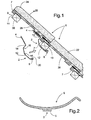
- the known tile binders typically consist of a stiff piece of round wire of steel with a strength of 16-1800 N/mm 2 , and they are shaped as shown in fig. 1.
- the known tile binder 2 comprises a straight free insertion part 4 for insertion from the lower end of the tile into the hole in the boss 5 of a tile 6, and a gripping end part 8 for anchoring in abutment against a rafter 10, and a slightly curved intermediate length 12 in between said parts, beginning with an approximately right-angled bend 14 followed by two consecutive 45° bends 16, 18, and ending with a bending-over 20 of the wire in towards itself to form the gripping end part 8, whereby the tile binder 2 is able to be placed extending around the underlying tile 22 and the rafter 10.
- the obtuse extending end of the bend is not intended to engage with the side of the rafter 10, but serves merely to stabilise the tile binder in the event of possible influence by outwardly-directed, transverse forces on the tile 6, and to prevent damage to the sub roof when the tile binder is mounted.
- the tile binder is secured in its position partly by friction which arises by the abutment pressure of the staggered end part against the rafter 10, and partly due to the fact that the laying boss 7 of the underlying tile prevents the straight insertion part 4 from sliding out of the hole 3 in the binding boss 5, cf. fig. 1.
- the known tile binders have certain disadvantages, e.g. they are very sensitive to incorrect rafter dimensions, which means that the anchoring becomes poor if the rafters are too narrow, and rafters which are too large in dimensions can cause wear damage to arise on the sub roof, and further that the straight free insertion end 4 placed in the boss 5 can give rise to an undesired, outwardly directed force on the upper end 24 of the tile 6 (indicated by the arrow 26 in fig. 1), for the reason that the gripping end part 8 is placed at a greater distance from the underside 28 of the tile.
- the tile binder for use for under-pointed roof constructions, where there is access to the undersides of the tiles after they have been laid.
- the tile binder comprises an upper bent-over end for insertion in the hole in the tile's binding boss from above, and a lower end which is of rectangular U-shape and intended to grip around the whole of the underlying rafter with the free end in between the rafter and the underside of the front end of the underlying tile.
- the tile binder also comprises an intermediate length with a spirally-wound flexible part which makes it possible to stretch the binder during insertion of the upper bent-over end in the tile's binding boss.
- the tile binder is intended for mounting after the tiles have been laid.
- an under-pointing (sealing) of the spaces in between the tiles is carried out with mortar, after which the binders are mounted in that the rectangular U-shaped lower end is led around the rafter, and the bent-over end of the binder is subsequently inserted in the hole in the binding boss, which is possible due to the good possibilities of access to the underside of the tiles.
- the inventor has acknowledged that the anchoring of the tile in accordance with the known technique (disclosed in DK 25298), which has previously been used in connection with under-pointed tiles, is even particularly expedient, in that the binder exercises a resulting downwards-directed force on the tiles, so that these hereby lie in a firmer manner against the underlying roof construction.
- the configuration of this known binder whereby this is secured around the whole of the underlying rafter, results however - due to inadequate space conditions when laying tiles on roof constructions with sub roof, and the lack of possibilities for access to the under side of the tiles for the subsequent mounting of the insertion end of the known tile binder - that this binder can not be used in the laying of tiles on roof constructions with sub roof.
- the object of the invention is thus to provide a method for the laying and anchoring of tiles on roof constructions of the kind disclosed (with sub roof), which ensures an effective and more durable securing of the tiles than with the known method which is used for roof constructions with sub roof, and also a binder for use in the execution of the method.
- This object is achieved by the introduction of the insertion part of a tile binder with a substantially inverted U-shaped insertion part, an intermediate length with a part which provides flexibility, and a gripping end part with a U or V-shaped bend, into the through-going hole in the tile's binding boss or similar insertion opening from the upper end of the binding boss, followed by the placing of the tile on the upper side of the underlying tile, after which the tile is tilted down so that the tile's laying boss is placed on top of the rafter at the top of the tile, whereby the free end of the gripping end part is turned in behind the underside of the rafter at the foot (lower end) of the tile, upon which the tile is pushed upwards, whereby the free end of the gripping end part is brought into abutment with the underside of the rafter at the foot of the tile, and by continued displacement of the tile, stretching (tensioning) of the flexible part of the tile binder, with the laying boss sliding on the outer side of the rafter
- a tile binder for use in the execution of the method according to the invention comprises a body (a length) of stiff but outwardly-flexible material comprising a substantially reversed U-shaped insertion part for insertion from above in a tile's binding boss or similar insertion opening, said insertion part, via an intermediate length comprising a part which provides elasticity in both the tile's longitudinal and transverse directions, standing in connection with an anchoring part, characterised in that the anchoring part comprises a substantially straight length having a free end which is concluded with a U- or V-shaped bend for engagement in the underside of the rafter nearest to the foot (lower end) of the tile extending in substantially the same plane as the reversed U-shaped insertion part.
- the directional deviation of the bend in relation to the straight extent of the anchoring part forms an angle within the interval of 90° - 225°, typically between 110° - 200°, and preferably within the interval 120° - 190°.
- tile binder according to the invention in combination with the method according to the invention, there is hereby achieved a particularly effective anchoring of tiles laid out on roof constructions with sub roof, in that in the correctly laid position on the rafters, by stretching of the elasticity-providing part, the tiles are drawn respectively in against the underlying tile and against the outer side of the rafters which support the front end of the tile.
- tile binder according to the invention there is thus achieved the same effective anchoring of tiles laid out on roof constructions with sub roof, than has hitherto been possible only when using the previously-mentioned tile binders for use with roof constructions with under-pointed tiles, where subsequent mounting of tile binders is possible as a result of unhindered access to the underside of the roof after the laying of the tiles.
- the configuration of the insertion part as the free end of a U-shaped insertion part makes it possible for the insertion part to be inserted from the upper end of the binding boss (unlike the known tile binders which are inserted in the through-going hole in the boss from below), and in combination with the gripping end part which is brought into abutment with the rafter at the foot of the tile, as already mentioned this results in a considerable improvement of the anchoring of the tile to the underlying roof construction.
- the tile binder according to the invention has the further advantage that it can be used together with rafters of different dimensions. Practical tests with the tile binder according to the invention have thus shown that this can be used together with rafters of three different dimensions (30/50, 50/50 and 40/60), which is not possible with the known tile binders where a specific type of binder must be used with rafters of specific dimensions.
- the obtuse end can be flattened so that there is hereby formed a pressure surface with an area which is greater than the cross-sectional area of the obtuse end.
- its middle section in between the insertion part and the gripping end part can extend in a substantially curved manner.
- an advantageous configuration of the curved extent of the middle part can be disclosed as being a bend in the plane of the U-shaped insertion part oriented towards the insertion part, standing in connection with the U-shaped insertion part, followed by an oppositely-directed (outwards-directed) bending of the middle section and thereafter a substantially straight piece continuing over to the elasticity-providing part which is concluded with the gripping end part.
- the elasticity-providing part in the middle section can be configured in different ways, but without waiving other configurations, a preferred embodiment hereof consists of at least one zig-zag bending (W-.shaped bending) of the middle section.
- W-.shaped bending zig-zag bending
- the possibility is hereby provided for an elastic increase in the length of the middle section when placing the gripping end part of the tile binder on the underside of the nearest rafter, in that a pull on the gripping end part will result in a stretching at the angle bends in the zig-zag-bent area.
- angles in the tips of the zig-zag bends when the tile binder is not mounted lie within the range of 60-120°, typically within 80-110° and typically between 90-100°.
- the length of the tile binder can also with advantage be adapted so that the angles of the angle bends in the elasticity-providing part when the tile binder is mounted are greater than 90°. It is hereby achieved that the tile binder according to the invention exercises an adequate downwards-directed force on the tiles, whereby the necessary anchoring of the roof is ensured.
- An adjustment of the flexibility and tractive force of the tile binder can also with advantage be effected by shortening/lengthening the straight section in between the bends in the zig-zag part in the elasticity-providing area.
- the tile binder according to the invention can with advantage consist of a piece of stiff, round wire, with a yield stress within the interval of 1400-1800 N/mm 2 .
- the tile binder can also with advantage consist of a piece of stiff, round wire with a diameter lying within the range of 1.0 - 4.0 mm, typically within the interval 1.5-3.0 mm, and typically within the interval 1.7-2.2 mm.
- the tile binder according to the invention With the tile binder according to the invention, savings can be achieved in wire due to the increased, better anchoring ability which is achieved by changing the engagement point of the tile binder in the boss.
- the presently prescribed wire diameter of 3.0 mm for tile binders of the known type can thus be reduced to a diameter of between 1.8-2.2 mm, whereby a saving in wire right up to 50% could be achieved.
- Fig. 1 shows one of the tile binders which are typically used for anchoring tiles on roof constructions with sub roof (not shown, but cf. fig. 3).
- a binder consists of a piece of stiff, round steel wire with a strength of 16-1800 N/mm 2 , and which typically has the shown configuration.
- the shown, known tile binder 2 comprises a straight, free insertion part 4 for insertion from the lower end of the tile in the hole 3 (cf. fig. 2) in the binding boss 5 of a tile 6, and an end part 8 for anchoring to a rafter 10, and an approximately curved middle section 12 in between said parts, beginning with an approximately right-angled bend 14 followed by two successive 45° bends 16, 18, and terminated with a bending-over 20 of the wire end in against itself to form an end part 8 which will not be able to damage the sub roof by penetration.
- the roof-tile binder 2 can thus be mounted extending around the laying boss 7 on the underlying tile 22 and the rafter 10.
- the laying boss 7 will be able to prevent the tile binder from falling out, in that with a downwards-directed displacement of the binder 2, the right-angle bend 14 will abut up against the front edge of the laying boss 7 before the insertion part is displaced out of the boss 5.
- the shown, known tile binder 2 is very sensitive to incorrect rafter dimensions, which means that the anchoring becomes poor if the rafters are too small, and rafter dimensions which are too great can result in wear damage occurring on the sub roof.
- rafter dimensions which are too great can result in the straight free insertion end 4 of the binder placed in the boss 5 giving rise to an undesired, outwards-directed force being applied to an upper end 24 of the tile 6, indicated by the arrow 26, this being a consequence of the gripping end part 8 being placed at a greater distance from the underside 28 of the tile than the displacement which is provided by the bends 14, 16, 18 in the middle section 12.
- the outwards-directed force 26 arises by the insertion part 4,which is housed in the hole 3 (cf. fig. 2) in the tile's boss 5, being turned so that the outer end of the gripping end part 4 exercises an outwards-directed pressure on the boss 5 and herewith the tile 6, the lower underside 28 of which is hereby pressed more firmly against the underlying tile 22, whereby the contact pressure of the tile's upper end on the overlying rafter 30 is considerably reduced as a result of the outwards-directed influence 26 from the roof-tile binder.
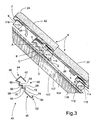
- Fig. 3 shows a roof-tile binder 40 according to the invention, respectively before and after insertion in a roof construction with sub roof 102.
- the roof construction also comprises underlying rafters 100, on the upper side of which the sub roof 102 is laid, for example in the form of a strong plastic foil.
- the sub roof is secured by a spacing batten 104 which is fastened to the outer side of the rafters.
- these components 100, 102, 104 are for the sake of clarity shown with spaces between them, but in practice they will be in abutment with one another.
- Rafters 110 are placed on the outside of the spacing battens at mutual intervals which are selected to suit the tiles 6 which are to be laid on the roof construction.
- the inner sides 112 of the rafters are in abutment with the spacing battens 104, and the outer sides 114 of the rafters are in abutment with the tiles 6.
- the rafters also have an upper side 116 and a lower side 118.
- the roof-tile binder 40 consists of a piece of stiff, round steel wire, typically with a yield stress lying in the range of 1400-1800 N/mm 2 .
- the tile binder 40 comprises an insertion part 42 which consists of the free end of an inverted U-shaped bending 44 of the one end of the middle section 46. It is hereby achieved that the insertion part 42 can be inserted in the hole 3 from the upper end 45 of the boss 5. At least a part of the bottom section 46 of the U-shaped bend 44 is hereby brought into abutment with the upper end surface 45 of the boss.
- the roof-tile binder also comprises a section 48 which comprises an elasticity-providing part 50 which allows an elastic extension of the distance between the bottom section 46 of the U-shaped bend 44 and a gripping end part 52 which preferably consists of a U- or V-shaped bending over of the free end 54 of the section 48.
- the gripping end part 52 is intended for fastening to the underside 118 of the rafter 10 at the foot of the tile.
- the elasticity-providing part 50 of the section 48 can be configured in different ways, but without waiving other configurations, the preferred embodiment shown here can consist of two successive zig-zag bends (W-shaped bending) of the middle section 48.
- the possibility is hereby provided for an elastic increase in the length of the middle section when placing the gripping end part 52 of the tile binder on the underside 118 of the nearest lying rafter 110, in that a pull on the gripping end part will result in a stretching at the angle bends 56, 58, 60 in the zig-zag-bent area.
- the configuration of the insertion part 42 as the free end of a U-shaped insertion part 44 enables the insertion part 42 to be inserted in the through-going hole 3 in the boss from the upper end 45, whereby at least a part of the bottom section 46 of the U-shaped bend 44 abuts up against the upper end surface 45 of the boss.
- This in combination with the gripping end part 52, which when the tile 6 is being laid is brought into engagement with the underside 118 of the rafter 110, results in a considerable improvement of the anchoring of the tile 6 to the underlying roof construction.
- the tile binder 40 according to the invention has the further advantage that it can be used together with rafters of different dimensions. Practical tests with the tile binder according to the invention have thus shown that this can be used together with rafters of three different dimensions (30/50, 50/50 and 40/60), which is not possible with the known tile binders where a specific type of binder must be used with rafters of specific dimensions.
- a tile 6 provided with a binder 40 according to the invention is laid on rafters 110.
- the tile 6 is laid after insertion of the insertion end 42 in the hole 3 in the boss 5, with the binder hanging down under the tile, after which the tile is tilted down so that the laying boss 7 at the upper end of the tile is brought into abutment with the outer side 114 of the overlying rafter 110.
- the obtusely-extending free end 54 of the gripping end part 52 is turned in behind the underside 118 of the rafter 110 at the foot of the tile, after which the tile is pushed slanting upwards in the direction of the arrow 120 until the tile's laying boss 7 passes the edge of the upper side 116 of the rafter, whereby the underside 28 of the tile is brought to rest against the outer side 114 of the rafter 110, and the underside 9 of the laying boss 7 is in abutment with the upper side 116 of the rafter.
- angles A, B, C, D in the zig-zag bends 56, 58, 59, 60 lie within the range of 60-120°, typically within the interval 80-110° and typically between 85-90°.
- the length of the tile binder is selected so that when the binder is mounted, the angles A, B, C and D of the bends 56, 58, 59, 60 in the elasticity-providing part 30 are greater than 90°, whereby it is achieved that the tile binder 40 according to the invention exercises sufficient downwards-directed force 64 on the tiles 6, whereby the necessary anchoring of the roof is ensured.
- the directional deviation of the bend in relation to the straight extent of the anchoring part can form an angle E within the interval of 90° - 225°, typically between 110° - 200° and preferably within the interval of 120° - 190°.
- the free end can also be rounded-off, flattened or pointed with the view to providing a preferred grip in the underside 118 of the rafter.
- a saving in wire can be achieved due to the increased, better anchoring ability which is obtained by changing the point of engagement of the roof-tile binder in the boss 5.
- a reduction will thus be able to be made in the presently prescribed wire diameter of 3.0 mm for tile binder of the known type to a diameter of 1.8-2.2 mm, whereby a saving in wire of right up to 50% will be able to be achieved.
- the inventor has acknowledged that the roof-tile binder according to the invention can assume other configurations.
- the elasticity-providing element 50 could thus be configured as a spirally-wound spring, and the section between the insertion part 42 and the gripping end part 52 could also be of other configurations.
- the binders could be configured in materials other than metal (steel wire), and the material could be of cross-sections other than circular (which is that which the steel wire normally has), but which, however will place requirements on the configuration of the tile where the opening for the insertion of the binder is concerned. Combinations of cross-sectional shapes and materials could also be envisaged.
Abstract
Description
- The present invention concerns a method for the laying and anchoring of pantiles on rafters on roof constructions with sub roof. The invention also concerns a tile binder of stiff material for use in the execution of the method, of the kind which is used for the laying and anchoring of pantiles on roof constructions with sub roof, and comprising an insertion part for insertion in the binding boss on the underside of the tile, and in extension herewith a part standing in connection with a gripping end part.
- Roof-tile binders are used in connection with the laying of roofs consisting of tiles or other materials (in the following mutually called tiles), with the view to achieving a certain anchoring of the tiles to the underlying rafters in the event of outwardly-directed wind forces as a result of the influence by wind on the roof construction.
- The underside of the tile, cf. fig. 1, comprises a
binding boss 5 and alaying boss 7 at the front edge. The binding boss, which consists of a projection on the underside of the tile, is provided with a through-goinghole 3, cf. fig. 3, disposed in the longitudinal direction of the tile for the accommodation of thestraight end part 4 of a wire-formed tile binder, the other end of which is staggered in relation to said end part, and which in the laying of the tile is introduced in behind the rafter closest to the foot (lower part) of the tile, or that rafter (10) on which the upper end of theunderlying tile 22 is supported, where the staggered end of the binder is in contact with that side of said rafter which faces towards the sub roof (not shown). Thelaying boss 7 consists of a projection on the underside of the tile at the top 24 (upper end) of the tile. In the correctly laid out position of the tile, the underedge 9 of the laying boss is in abutment with theupper edge 11 of anunderlying rafter 30, so that the tile is held and secured by the rafter (for the sake of clarity and understanding, in figs. 1 and 3 a clearance is shown in between the under edge of the laying boss and theupper edge 11 of the rafter 30). - The known tile binders typically consist of a stiff piece of round wire of steel with a strength of 16-1800 N/mm2, and they are shaped as shown in fig. 1. The known
tile binder 2 comprises a straightfree insertion part 4 for insertion from the lower end of the tile into the hole in theboss 5 of atile 6, and agripping end part 8 for anchoring in abutment against arafter 10, and a slightly curvedintermediate length 12 in between said parts, beginning with an approximately right-angled bend 14 followed by two consecutive 45°bends gripping end part 8, whereby thetile binder 2 is able to be placed extending around theunderlying tile 22 and therafter 10. It must be noted that in the mounted state, the obtuse extending end of the bend is not intended to engage with the side of therafter 10, but serves merely to stabilise the tile binder in the event of possible influence by outwardly-directed, transverse forces on thetile 6, and to prevent damage to the sub roof when the tile binder is mounted. The tile binder is secured in its position partly by friction which arises by the abutment pressure of the staggered end part against therafter 10, and partly due to the fact that thelaying boss 7 of the underlying tile prevents thestraight insertion part 4 from sliding out of thehole 3 in thebinding boss 5, cf. fig. 1. - The known tile binders, however, have certain disadvantages, e.g. they are very sensitive to incorrect rafter dimensions, which means that the anchoring becomes poor if the rafters are too narrow, and rafters which are too large in dimensions can cause wear damage to arise on the sub roof, and further that the straight
free insertion end 4 placed in theboss 5 can give rise to an undesired, outwardly directed force on theupper end 24 of the tile 6 (indicated by thearrow 26 in fig. 1), for the reason that thegripping end part 8 is placed at a greater distance from theunderside 28 of the tile. This outwardly-directed force arises in that the insertion part placed in the tile's boss is turned, whereby the outer end of the insertion part exercises an outwardly-directed pressure on the boss, and herewith on the tile, which results in a considerable reduction in the abutments pressure of the upper end of the tile on the underlying rafter. All in all, the latter disadvantage can give rise to an inexpedient effect of the tile binders when the rafters and binders do not correspond with each other. The known tile binders are thus delivered in different dimensions, corresponding to a rafter of a given size, which thus means that a craftsman should/must hold a stock of tile binders of different dimensions. - From DK 25298 there is known a tile binder for use for under-pointed roof constructions, where there is access to the undersides of the tiles after they have been laid. The tile binder comprises an upper bent-over end for insertion in the hole in the tile's binding boss from above, and a lower end which is of rectangular U-shape and intended to grip around the whole of the underlying rafter with the free end in between the rafter and the underside of the front end of the underlying tile. The tile binder also comprises an intermediate length with a spirally-wound flexible part which makes it possible to stretch the binder during insertion of the upper bent-over end in the tile's binding boss. The tile binder is intended for mounting after the tiles have been laid. After the tiles have been laid, an under-pointing (sealing) of the spaces in between the tiles is carried out with mortar, after which the binders are mounted in that the rectangular U-shaped lower end is led around the rafter, and the bent-over end of the binder is subsequently inserted in the hole in the binding boss, which is possible due to the good possibilities of access to the underside of the tiles.
- The inventor has acknowledged that the anchoring of the tile in accordance with the known technique (disclosed in DK 25298), which has previously been used in connection with under-pointed tiles, is even particularly expedient, in that the binder exercises a resulting downwards-directed force on the tiles, so that these hereby lie in a firmer manner against the underlying roof construction. The configuration of this known binder, whereby this is secured around the whole of the underlying rafter, results however - due to inadequate space conditions when laying tiles on roof constructions with sub roof, and the lack of possibilities for access to the under side of the tiles for the subsequent mounting of the insertion end of the known tile binder - that this binder can not be used in the laying of tiles on roof constructions with sub roof.
- The object of the invention is thus to provide a method for the laying and anchoring of tiles on roof constructions of the kind disclosed (with sub roof), which ensures an effective and more durable securing of the tiles than with the known method which is used for roof constructions with sub roof, and also a binder for use in the execution of the method.
- This object is achieved by the introduction of the insertion part of a tile binder with a substantially inverted U-shaped insertion part, an intermediate length with a part which provides flexibility, and a gripping end part with a U or V-shaped bend, into the through-going hole in the tile's binding boss or similar insertion opening from the upper end of the binding boss, followed by the placing of the tile on the upper side of the underlying tile, after which the tile is tilted down so that the tile's laying boss is placed on top of the rafter at the top of the tile, whereby the free end of the gripping end part is turned in behind the underside of the rafter at the foot (lower end) of the tile, upon which the tile is pushed upwards, whereby the free end of the gripping end part is brought into abutment with the underside of the rafter at the foot of the tile, and by continued displacement of the tile, stretching (tensioning) of the flexible part of the tile binder, with the laying boss sliding on the outer side of the rafter at the top of the tile, until the front end of the tile falls down on the outer side of the rafter and rests on this with the back of the laying boss in abutment with the upper side of the rafter, whereby the tile is secured.
- There is hereby achieved a considerably improved securing of the tile in comparison with the known method, in that the tile is secured in its correct position by a downwards-directed force brought about by the stretching of the flexible part of the tile binder as a consequence of the anchoring of the gripping end part in the underside of the underlying rafter, which results in both the front edge and the rear edge of the tile being drawn respectively against the foremost rafter and the upper edge of the preceding/underlying tile.
- A tile binder for use in the execution of the method according to the invention comprises a body (a length) of stiff but outwardly-flexible material comprising a substantially reversed U-shaped insertion part for insertion from above in a tile's binding boss or similar insertion opening, said insertion part, via an intermediate length comprising a part which provides elasticity in both the tile's longitudinal and transverse directions, standing in connection with an anchoring part, characterised in that the anchoring part comprises a substantially straight length having a free end which is concluded with a U- or V-shaped bend for engagement in the underside of the rafter nearest to the foot (lower end) of the tile extending in substantially the same plane as the reversed U-shaped insertion part.
- Out of regard for the achieving of an expedient anchoring of the free end of the bent-over part, it can be mentioned that the directional deviation of the bend in relation to the straight extent of the anchoring part forms an angle within the interval of 90° - 225°, typically between 110° - 200°, and preferably within the
interval 120° - 190°. - By use of the tile binder according to the invention in combination with the method according to the invention, there is hereby achieved a particularly effective anchoring of tiles laid out on roof constructions with sub roof, in that in the correctly laid position on the rafters, by stretching of the elasticity-providing part, the tiles are drawn respectively in against the underlying tile and against the outer side of the rafters which support the front end of the tile. With the tile binder according to the invention, there is thus achieved the same effective anchoring of tiles laid out on roof constructions with sub roof, than has hitherto been possible only when using the previously-mentioned tile binders for use with roof constructions with under-pointed tiles, where subsequent mounting of tile binders is possible as a result of unhindered access to the underside of the roof after the laying of the tiles.
- Laboratory tests have also shown that roof constructions with sub roof provided with tiles anchored with tile binders according to the present invention have been considerably more resistant to wind effects than roofs where the tiles are anchored with the commonly-known tile binders for anchoring of tiles laid on roof constructions with sub roof.
- The configuration of the insertion part as the free end of a U-shaped insertion part makes it possible for the insertion part to be inserted from the upper end of the binding boss (unlike the known tile binders which are inserted in the through-going hole in the boss from below), and in combination with the gripping end part which is brought into abutment with the rafter at the foot of the tile, as already mentioned this results in a considerable improvement of the anchoring of the tile to the underlying roof construction. The reason for this is that when the tile binder is mounted, with the altered point of engagement in the boss, an inclined, downwards-directed resulting force on the tile is achieved in relation to the surface of the tile, regardless of deviations in rafter dimensions as well as in the breadth and the height of the rafters and tiles used in the roof construction, in that compensation is made for these deviations by the elasticity-providing part of the binder. With rafters which are too large, it is thus achieved, unlike with the known tile binder cf. the above, that the downwards-directed tractive force on the tile is increased with subsequent increase in the stability of the roof. With rafters which are too small, it is achieved merely that the force is reduced, though not more than the said inclined downwards-directed force can be maintained. Consequently, when use is made of the tile binder according to the invention, no outwardly-directed force which could give rise to the roofing tiles becoming unstable is applied to the upper end of the tile under any positioning/building-in/mounting conditions whatsoever. Moreover, the tile binder according to the invention has the further advantage that it can be used together with rafters of different dimensions. Practical tests with the tile binder according to the invention have thus shown that this can be used together with rafters of three different dimensions (30/50, 50/50 and 40/60), which is not possible with the known tile binders where a specific type of binder must be used with rafters of specific dimensions.
- With the view to achieving an expedient distribution of pressure in between the obtuse end of the bend and the rafter, the obtuse end can be flattened so that there is hereby formed a pressure surface with an area which is greater than the cross-sectional area of the obtuse end.
- With the view to providing the tile binder with additional flexibility, its middle section in between the insertion part and the gripping end part can extend in a substantially curved manner.
- Without waiving any other configurations, an advantageous configuration of the curved extent of the middle part can be disclosed as being a bend in the plane of the U-shaped insertion part oriented towards the insertion part, standing in connection with the U-shaped insertion part, followed by an oppositely-directed (outwards-directed) bending of the middle section and thereafter a substantially straight piece continuing over to the elasticity-providing part which is concluded with the gripping end part.
- The elasticity-providing part in the middle section can be configured in different ways, but without waiving other configurations, a preferred embodiment hereof consists of at least one zig-zag bending (W-.shaped bending) of the middle section. The possibility is hereby provided for an elastic increase in the length of the middle section when placing the gripping end part of the tile binder on the underside of the nearest rafter, in that a pull on the gripping end part will result in a stretching at the angle bends in the zig-zag-bent area.
- The angles in the tips of the zig-zag bends when the tile binder is not mounted lie within the range of 60-120°, typically within 80-110° and typically between 90-100°.
- The length of the tile binder can also with advantage be adapted so that the angles of the angle bends in the elasticity-providing part when the tile binder is mounted are greater than 90°. It is hereby achieved that the tile binder according to the invention exercises an adequate downwards-directed force on the tiles, whereby the necessary anchoring of the roof is ensured.
- An adjustment of the flexibility and tractive force of the tile binder can also with advantage be effected by shortening/lengthening the straight section in between the bends in the zig-zag part in the elasticity-providing area.
- The tile binder according to the invention can with advantage consist of a piece of stiff, round wire, with a yield stress within the interval of 1400-1800 N/mm2.
- The tile binder can also with advantage consist of a piece of stiff, round wire with a diameter lying within the range of 1.0 - 4.0 mm, typically within the interval 1.5-3.0 mm, and typically within the interval 1.7-2.2 mm.
- With the tile binder according to the invention, savings can be achieved in wire due to the increased, better anchoring ability which is achieved by changing the engagement point of the tile binder in the boss. In accordance with future EU standards, the presently prescribed wire diameter of 3.0 mm for tile binders of the known type can thus be reduced to a diameter of between 1.8-2.2 mm, whereby a saving in wire right up to 50% could be achieved.
- In the following, the invention will be explained in more detail with reference to the drawing, where
- Fig. 1 is a side view of a tile binder of the kind used in roof constructions with sub roof, where the same is shown inserted in a roof construction,
- Fig. 2 is an end view of a pantile,
- Fig. 3 is a side view of a tile binder according to the invention, and the same inserted in a roof construction with sub roof, and
- Fig. 4 illustrates the laying of a tile provided with a tile binder according to the invention.
-
- Fig. 1 shows one of the tile binders which are typically used for anchoring tiles on roof constructions with sub roof (not shown, but cf. fig. 3). Such a binder consists of a piece of stiff, round steel wire with a strength of 16-1800 N/mm2, and which typically has the shown configuration.
- The shown, known
tile binder 2 comprises a straight,free insertion part 4 for insertion from the lower end of the tile in the hole 3 (cf. fig. 2) in thebinding boss 5 of atile 6, and anend part 8 for anchoring to arafter 10, and an approximatelycurved middle section 12 in between said parts, beginning with an approximately right-angled bend 14 followed by two successive 45°bends end part 8 which will not be able to damage the sub roof by penetration. With this configuration, the roof-tile binder 2 can thus be mounted extending around thelaying boss 7 on theunderlying tile 22 and therafter 10. Moreover, the layingboss 7 will be able to prevent the tile binder from falling out, in that with a downwards-directed displacement of thebinder 2, the right-angle bend 14 will abut up against the front edge of the layingboss 7 before the insertion part is displaced out of theboss 5. - However, the shown, known
tile binder 2 is very sensitive to incorrect rafter dimensions, which means that the anchoring becomes poor if the rafters are too small, and rafter dimensions which are too great can result in wear damage occurring on the sub roof. Moreover, rafter dimensions which are too great can result in the straightfree insertion end 4 of the binder placed in theboss 5 giving rise to an undesired, outwards-directed force being applied to anupper end 24 of thetile 6, indicated by thearrow 26, this being a consequence of thegripping end part 8 being placed at a greater distance from theunderside 28 of the tile than the displacement which is provided by thebends middle section 12. The outwards-directedforce 26 arises by theinsertion part 4,which is housed in the hole 3 (cf. fig. 2) in the tile'sboss 5, being turned so that the outer end of thegripping end part 4 exercises an outwards-directed pressure on theboss 5 and herewith thetile 6, thelower underside 28 of which is hereby pressed more firmly against the underlyingtile 22, whereby the contact pressure of the tile's upper end on the overlyingrafter 30 is considerably reduced as a result of the outwards-directedinfluence 26 from the roof-tile binder. - Fig. 3 shows a roof-
tile binder 40 according to the invention, respectively before and after insertion in a roof construction withsub roof 102. The roof construction also comprisesunderlying rafters 100, on the upper side of which thesub roof 102 is laid, for example in the form of a strong plastic foil. The sub roof is secured by a spacing batten 104 which is fastened to the outer side of the rafters. In fig. 3, thesecomponents Rafters 110 are placed on the outside of the spacing battens at mutual intervals which are selected to suit thetiles 6 which are to be laid on the roof construction. Theinner sides 112 of the rafters are in abutment with the spacing battens 104, and theouter sides 114 of the rafters are in abutment with thetiles 6. The rafters also have anupper side 116 and alower side 118. - In the shown embodiment, the roof-
tile binder 40 consists of a piece of stiff, round steel wire, typically with a yield stress lying in the range of 1400-1800 N/mm2. Thetile binder 40 comprises aninsertion part 42 which consists of the free end of an inverted U-shaped bending 44 of the one end of themiddle section 46. It is hereby achieved that theinsertion part 42 can be inserted in thehole 3 from the upper end 45 of theboss 5. At least a part of thebottom section 46 of theU-shaped bend 44 is hereby brought into abutment with the upper end surface 45 of the boss. - The roof-tile binder also comprises a
section 48 which comprises an elasticity-providingpart 50 which allows an elastic extension of the distance between thebottom section 46 of theU-shaped bend 44 and agripping end part 52 which preferably consists of a U- or V-shaped bending over of thefree end 54 of thesection 48. Thegripping end part 52 is intended for fastening to theunderside 118 of therafter 10 at the foot of the tile. - The elasticity-providing
part 50 of thesection 48 can be configured in different ways, but without waiving other configurations, the preferred embodiment shown here can consist of two successive zig-zag bends (W-shaped bending) of themiddle section 48. The possibility is hereby provided for an elastic increase in the length of the middle section when placing thegripping end part 52 of the tile binder on theunderside 118 of thenearest lying rafter 110, in that a pull on the gripping end part will result in a stretching at the angle bends 56, 58, 60 in the zig-zag-bent area. - The configuration of the
insertion part 42 as the free end of aU-shaped insertion part 44 enables theinsertion part 42 to be inserted in the through-goinghole 3 in the boss from the upper end 45, whereby at least a part of thebottom section 46 of theU-shaped bend 44 abuts up against the upper end surface 45 of the boss. This, in combination with thegripping end part 52, which when thetile 6 is being laid is brought into engagement with theunderside 118 of therafter 110, results in a considerable improvement of the anchoring of thetile 6 to the underlying roof construction. The reason for this is that when the tile binder is mounted in theboss 5, with the changed point of engagement in the tile's upwardly-facing side 45, there is achieved a resulting force on thetile 6 which in relation to thesurface 62 of the tile is in an inclined downwards direction (indicated by the arrow 64), regardless of deviations in the dimensions of therafter 110, on theunderside 118 of which thegripping end part 52 of the tile binder is anchored, in that compensation is made for these deviations by the elasticity-providingpart 50. With use of the tile binder according to the invention, theupper end 24 of the tile will hereby always be secured by the force directed towards an underlyingrafter 30. - With rafters which are too large, it is thus achieved, unlike with the known tile binder cf. the above, that the downwards-directed tractive force on the tile is increased with subsequent increase in the stability of the roof. With rafters which are too small, it is achieved merely that the force is reduced, though not more than the said inclined downwards-directed force can be maintained. Consequently, when use is made of the tile binder according to the invention, no outwardly-directed force which could give rise to the roofing tiles becoming unstable is applied to the upper end of the tile under any positioning/building-in/mounting conditions whatsoever.
- Moreover, the
tile binder 40 according to the invention has the further advantage that it can be used together with rafters of different dimensions. Practical tests with the tile binder according to the invention have thus shown that this can be used together with rafters of three different dimensions (30/50, 50/50 and 40/60), which is not possible with the known tile binders where a specific type of binder must be used with rafters of specific dimensions. - In fig. 4 it is shown how a
tile 6 provided with abinder 40 according to the invention is laid onrafters 110. Thetile 6 is laid after insertion of theinsertion end 42 in thehole 3 in theboss 5, with the binder hanging down under the tile, after which the tile is tilted down so that the layingboss 7 at the upper end of the tile is brought into abutment with theouter side 114 of theoverlying rafter 110. In the tilting movement, the obtusely-extendingfree end 54 of thegripping end part 52 is turned in behind theunderside 118 of therafter 110 at the foot of the tile, after which the tile is pushed slanting upwards in the direction of thearrow 120 until the tile's layingboss 7 passes the edge of theupper side 116 of the rafter, whereby theunderside 28 of the tile is brought to rest against theouter side 114 of therafter 110, and theunderside 9 of the layingboss 7 is in abutment with theupper side 116 of the rafter. At the same time with said displacement of thetile 6, there occurs a displacement of thebinder 10, whereby thefree end 54 of thegripping end part 52 is now brought into abutment with theunderside 118 of therafter 110 at the foot of the tile. With continued displacement of the tile towards its final position, a tractive force in the longitudinal direction is applied to the elasticity-providingpart 50, which results in a downwards-directed pull on thetile 6. - Before the roof-tile binder is mounted, the angles A, B, C, D in the zig-zag bends 56, 58, 59, 60 lie within the range of 60-120°, typically within the interval 80-110° and typically between 85-90°.
- The length of the tile binder is selected so that when the binder is mounted, the angles A, B, C and D of the
bends part 30 are greater than 90°, whereby it is achieved that thetile binder 40 according to the invention exercises sufficient downwards-directedforce 64 on thetiles 6, whereby the necessary anchoring of the roof is ensured. - Moreover, in the production of the roof-
tile binders 40 according to the invention, it will be possible to effect an adjustment of the flexibility and tractive power of thebinder 40 by shortening/lengthening thesections area 50. - With the view to achieving a suitable anchoring of the bent-over
free end 54 at thegripping end part 52, it can be mentioned that the directional deviation of the bend in relation to the straight extent of the anchoring part can form an angle E within the interval of 90° - 225°, typically between 110° - 200° and preferably within the interval of 120° - 190°. The free end can also be rounded-off, flattened or pointed with the view to providing a preferred grip in theunderside 118 of the rafter. - With the roof-
tile binder 40 according to the invention, a saving in wire can be achieved due to the increased, better anchoring ability which is obtained by changing the point of engagement of the roof-tile binder in theboss 5. In accordance with future EF standards, a reduction will thus be able to be made in the presently prescribed wire diameter of 3.0 mm for tile binder of the known type to a diameter of 1.8-2.2 mm, whereby a saving in wire of right up to 50% will be able to be achieved. - With the invention, there is thus disclosed a new roof-tile binder which, in addition to eliminating the disadvantages connected with the use of roof-tile binders of the known type, is also resource-saving in production and herewith cheaper to produce.
- The inventor has acknowledged that the roof-tile binder according to the invention can assume other configurations. The elasticity-providing
element 50 could thus be configured as a spirally-wound spring, and the section between theinsertion part 42 and thegripping end part 52 could also be of other configurations. Moreover, it is also envisaged that the binders could be configured in materials other than metal (steel wire), and the material could be of cross-sections other than circular (which is that which the steel wire normally has), but which, however will place requirements on the configuration of the tile where the opening for the insertion of the binder is concerned. Combinations of cross-sectional shapes and materials could also be envisaged. - This does not, however, change the basic concept of the invention, which is based on the provision of a roof-tile binder for use in the laying of tiles on roof constructions with sub roof, which has considerably increased the strength of the anchoring of the tiles in comparison to that which has hitherto been possible to achieve with roof-tile binders currently used for roof constructions of this type. This is effected by making use partly of the technique disclosed in DK patent no. 252898, where the insertion of the roof-tile binder's insertion part takes place from the upper side of the boss, combined with the establishing of a suitable
gripping end part 52 with afree end 54 which can easily be brought into engagement in theunderside 118 of the rafter at the foot of the tile, and furthermore by giving the length of the roof-tile binder an elasticity-providing part which, when the tile is laid, is tensioned and herewith subsequently gives rise to a constantly-applied downwards-directed force on the tile in towards therafters 110, hereby achieving a considerably better anchoring of the tile to the underlying supporting roof construction.
Claims (13)
- Method for the laying and anchoring of tiles (6) on roof constructions with sub roof, characterised in that the insertion part (42) of a roof-tile binder (40) with a substantially U-shaped insertion part (44), a section (46) with an elasticity-providing part (50), and a gripping end part (52) with a U- or V-shaped bend, is inserted in the through-going hole in the tile's binding boss (5) or similar insertion opening from the upper end of the binding boss, followed by the placing of the tile (6) with the foot on the upper side of the underlying tile (22), after which the tile is tilted down so that the tile's laying boss (7) is placed on top of the rafter (110) at the top of the tile, whereby the free end (54) of the gripping end part (52) is turned in behind the underside (118) of the rafter (110) at the foot of the tile, whereupon the tile (6) is pushed upwards, whereby the free end (54) of the gripping end part is brought into abutment with the underside 118 of the rafter 110 at the foot of the tile, and whereby a further displacement of the tile (6) gives rise to a stretching of the binder's elasticity-providing part (50), with the laying boss (7) sliding on the outer side (114) of the rafter (110) at the top of the tile until the front end of the tile falls down on the outer side (114) of the rafter, and rests on this with the back (9) of the laying boss (7) in abutment with the upper side (116) of the rafter, whereby the tile is secured.
- Roof-tile binder (40) for use in the execution of the method according to claim 1, and comprising a body of stiff but still outwardly-flexible material, comprising a substantially inverted U-shaped insertion part (42, 44) for insertion from above in the binding boss (5) in a tile (6) or similar insertion opening, said insertion part (42) comprising via a bottom part (46) an elasticity-providing part (50) in both the longitudinal and transverse direction of the tile which stands in connection with an anchoring part (48), characterised in that the anchoring part (48) comprises a substantially straight section with a free end (54) which ends in a U- or V-shaped bend (52) for engagement in the underside (118) of the rafter (110) nearest to the foot (lower end) of the tile, said bend (52) extending in substantially the same plane as the inverted U-shaped insertion part (44).
- Roof-tile binder (40) according to claim 2, characterised in that the directional deviation of the bend (52) in relation to the straight section of the anchoring part (48) forms an angle within the interval 90° - 225°, typically between 110° - 200° and preferably within the interval 120° - 190°.
- Roof-tile binder (40) according to claim 2 or 3, characterised in that the obtuse end (54) of the bend (52) is flattened, thus forming a pressure surface with an area which is greater than the cross-sectional area of the obtuse part.
- Roof-tile binder (40) according to any of the claims 2-4, characterised in that the obtuse end (54) of the bend (52) is pointed.
- Roof-tile binder according to any of the claims 2-5, characterised in that bottom section (46) extends in a substantially curved manner in between the insertion part (42, 44) and the gripping end part (52).
- Roof-tile binder (40) according to any of the claims 2-6, characterised in that the curved extent of the bottom section (46) is given as a bend in the plane of the U-shaped insertion part (44) oriented in towards the insertion part (42), followed by an oppositely-directed bending of the section (46), and thereafter a substantially straight piece leading to an elasticity-providing part (50), which at its end comprises an angle before a straight part (48) which ends in a gripping end part (52) with a bent-over obtuse projecting free end in substantially the same plane as the U-shaped insertion part (44).
- Roof-tile binder (40) according to any of the claims 2-7, characterised in that the elasticity-providing part (50) in the section (46) consists of at least one zig-zag bend (50) and preferably two consecutive zig-zag bends.
- Roof-tile binder (40) according to claim 8, characterised in that the angles in the zig-zag bends in the binder's unmounted state lie within the range of 60-120°, preferably within 80-110° and typically between 90-100°.
- Roof-tile binder (40) according to claim 8 or 9, characterised in that its length is selected so that when the tile binder is mounted, the angles in the angle bends in the elasticity-providing part (50) are greater than 90°.
- Roof-tile binder (40) according to any of the claims 8-10, characterised in that the adjustment of the flexibility and the tractive force of the binder is effected by shortening/lengthening the straight sections in between the bends in the zig-zag section in the elasticity-providing area (50).
- Roof-tile binder (40) according to any of the claims 1-11, characterised in that it consists of a piece of stiff, round wire with a yield stress lying within the interval 1400-1800 N/mm2.
- Roof-tile binder (40) according to any of the claims 12, characterised in that it consists of a piece of stiff, round wire with a diameter lying within the interval 1.0-4.0 mm, typically within the interval 1.5-3.0 mm and typically between 1.7-2.2 mm.
Applications Claiming Priority (3)
| Application Number | Priority Date | Filing Date | Title |
|---|---|---|---|
| DK108599 | 1999-08-03 | ||
| DK199901085A DK199901085A (en) | 1999-08-03 | 1999-08-03 | Roof tiles Binder |
| PCT/DK2000/000434 WO2001009457A2 (en) | 1999-08-03 | 2000-08-03 | Method and binder for laying and anchoring pantiles on roof constructions comprising sub roof |
Publications (2)
| Publication Number | Publication Date |
|---|---|
| EP1206608A2 EP1206608A2 (en) | 2002-05-22 |
| EP1206608B1 true EP1206608B1 (en) | 2005-12-28 |
Family
ID=8100834
Family Applications (1)
| Application Number | Title | Priority Date | Filing Date |
|---|---|---|---|
| EP00951268A Expired - Lifetime EP1206608B1 (en) | 1999-08-03 | 2000-08-03 | Method and binder for laying and anchoring pantiles on roof constructions comprising sub roof |
Country Status (6)
| Country | Link |
|---|---|
| EP (1) | EP1206608B1 (en) |
| AT (1) | ATE314536T1 (en) |
| AU (1) | AU6426400A (en) |
| DE (1) | DE60025220T2 (en) |
| DK (2) | DK199901085A (en) |
| WO (1) | WO2001009457A2 (en) |
Cited By (1)
| Publication number | Priority date | Publication date | Assignee | Title |
|---|---|---|---|---|
| DE202015003114U1 (en) | 2014-10-29 | 2015-05-04 | Marco Rinaldi | Security system for roof tiles |
Families Citing this family (2)
| Publication number | Priority date | Publication date | Assignee | Title |
|---|---|---|---|---|
| FR2838144A1 (en) * | 2002-04-04 | 2003-10-10 | Francis Noirot | Fixing for holding tiles in place during gales comprises traction spring fixed around lath and on tile |
| EP1522649A1 (en) * | 2003-10-07 | 2005-04-13 | Francis Noirot | Storm proof fastening device for roof tiles |
Family Cites Families (5)
| Publication number | Priority date | Publication date | Assignee | Title |
|---|---|---|---|---|
| DK25298C (en) * | 1919-12-08 | Christen Nielsen | Roof tile binder. | |
| SE53556C1 (en) * | ||||
| DE148026C (en) * | ||||
| FR33862E (en) * | 1927-05-18 | 1929-03-26 | Tile fixing system | |
| DE3333937A1 (en) * | 1983-09-20 | 1985-04-04 | Midtjysk Murbinderfabrik A/S, Viborg | Roof tile and bonder |
-
1999
- 1999-08-03 DK DK199901085A patent/DK199901085A/en not_active Application Discontinuation
-
2000
- 2000-08-03 EP EP00951268A patent/EP1206608B1/en not_active Expired - Lifetime
- 2000-08-03 AU AU64264/00A patent/AU6426400A/en not_active Abandoned
- 2000-08-03 DK DK00951268T patent/DK1206608T3/en active
- 2000-08-03 DE DE60025220T patent/DE60025220T2/en not_active Expired - Lifetime
- 2000-08-03 AT AT00951268T patent/ATE314536T1/en not_active IP Right Cessation
- 2000-08-03 WO PCT/DK2000/000434 patent/WO2001009457A2/en active IP Right Grant
Cited By (2)
| Publication number | Priority date | Publication date | Assignee | Title |
|---|---|---|---|---|
| DE202015003114U1 (en) | 2014-10-29 | 2015-05-04 | Marco Rinaldi | Security system for roof tiles |
| DE102014015900A1 (en) | 2014-10-29 | 2016-05-04 | Michael Wille | Security system for roof tiles |
Also Published As
| Publication number | Publication date |
|---|---|
| DK199901085A (en) | 2001-02-04 |
| EP1206608A2 (en) | 2002-05-22 |
| DE60025220D1 (en) | 2006-02-02 |
| WO2001009457A2 (en) | 2001-02-08 |
| DK1206608T3 (en) | 2006-05-15 |
| ATE314536T1 (en) | 2006-01-15 |
| AU6426400A (en) | 2001-02-19 |
| WO2001009457A3 (en) | 2001-08-09 |
| DE60025220T2 (en) | 2006-08-31 |
Similar Documents
| Publication | Publication Date | Title |
|---|---|---|
| EP0687337B1 (en) | Sloping roof provided with roofing tiles and tile hook to be used for a roof of this type | |
| MX2012006871A (en) | Seismic clip. | |
| US7444790B2 (en) | Weather strips | |
| EP1206608B1 (en) | Method and binder for laying and anchoring pantiles on roof constructions comprising sub roof | |
| CA2006701C (en) | Snow guard | |
| GB2101172A (en) | Tile clips | |
| EP1698739B1 (en) | system for fastening roofing tiles provided on a pitched roof surface, assembly for such a system as well as method for fastening roofing tiles to a pitched roof surface | |
| SK281755B6 (en) | Tile retaining storm hook | |
| EP1424454B1 (en) | Binder for interlocking tiles | |
| EP3341536B1 (en) | A roof tile clip | |
| AU2018102155A4 (en) | Roof Tile Anchor | |
| GB2321479A (en) | Roof ridge tiles, and their fixing | |
| CN102884259A (en) | A concealed fixing retaining clip for roof cladding sheets with profiled ribs | |
| EP0851069B1 (en) | A profiled sheet-metal roofing element for buildings | |
| AU778706B2 (en) | Weather strips | |
| EP1905917A1 (en) | Tile hook, pitched roof and method for covering a pitched roof | |
| HK1071176A1 (en) | Weather strips | |
| AU709435B3 (en) | Securing and weatherproofing roof tiles | |
| EP0240510A1 (en) | Tile fixing system. | |
| KR200205643Y1 (en) | The metallic roofing tile provided with the folded portion on it's both sides | |
| HU220926B1 (en) | Weather-proof arrangement for roof sheets | |
| JP3826250B2 (en) | Metal folded plate roof structure and metal folding plate roof presser member | |
| RU2279516C2 (en) | Cover strips | |
| AU638862B2 (en) | An eave and fascia | |
| IES980642A2 (en) | Improvements in and relating to ridge cappings |
Legal Events
| Date | Code | Title | Description |
|---|---|---|---|
| PUAI | Public reference made under article 153(3) epc to a published international application that has entered the european phase |
Free format text: ORIGINAL CODE: 0009012 |
|
| 17P | Request for examination filed |
Effective date: 20020301 |
|
| AX | Request for extension of the european patent |
Free format text: AL;LT PAYMENT 20020301;LV PAYMENT 20020301;MK;RO;SI |
|
| 19A | Proceedings stayed before grant |
Effective date: 20020923 |
|
| 19F | Resumption of proceedings before grant (after stay of proceedings) |
Effective date: 20030926 |
|
| GRAP | Despatch of communication of intention to grant a patent |
Free format text: ORIGINAL CODE: EPIDOSNIGR1 |
|
| GRAS | Grant fee paid |
Free format text: ORIGINAL CODE: EPIDOSNIGR3 |
|
| GRAA | (expected) grant |
Free format text: ORIGINAL CODE: 0009210 |
|
| AK | Designated contracting states |
Kind code of ref document: B1 Designated state(s): AT BE CH CY DE DK ES FI FR GB GR IE IT LI LU MC NL PT SE |
|
| AX | Request for extension of the european patent |
Extension state: LT LV |
|
| PG25 | Lapsed in a contracting state [announced via postgrant information from national office to epo] |
Ref country code: IT Free format text: LAPSE BECAUSE OF FAILURE TO SUBMIT A TRANSLATION OF THE DESCRIPTION OR TO PAY THE FEE WITHIN THE PRESCRIBED TIME-LIMIT;WARNING: LAPSES OF ITALIAN PATENTS WITH EFFECTIVE DATE BEFORE 2007 MAY HAVE OCCURRED AT ANY TIME BEFORE 2007. THE CORRECT EFFECTIVE DATE MAY BE DIFFERENT FROM THE ONE RECORDED. Effective date: 20051228 Ref country code: LI Free format text: LAPSE BECAUSE OF FAILURE TO SUBMIT A TRANSLATION OF THE DESCRIPTION OR TO PAY THE FEE WITHIN THE PRESCRIBED TIME-LIMIT Effective date: 20051228 Ref country code: BE Free format text: LAPSE BECAUSE OF FAILURE TO SUBMIT A TRANSLATION OF THE DESCRIPTION OR TO PAY THE FEE WITHIN THE PRESCRIBED TIME-LIMIT Effective date: 20051228 Ref country code: CH Free format text: LAPSE BECAUSE OF FAILURE TO SUBMIT A TRANSLATION OF THE DESCRIPTION OR TO PAY THE FEE WITHIN THE PRESCRIBED TIME-LIMIT Effective date: 20051228 Ref country code: FI Free format text: LAPSE BECAUSE OF FAILURE TO SUBMIT A TRANSLATION OF THE DESCRIPTION OR TO PAY THE FEE WITHIN THE PRESCRIBED TIME-LIMIT Effective date: 20051228 Ref country code: NL Free format text: LAPSE BECAUSE OF FAILURE TO SUBMIT A TRANSLATION OF THE DESCRIPTION OR TO PAY THE FEE WITHIN THE PRESCRIBED TIME-LIMIT Effective date: 20051228 Ref country code: AT Free format text: LAPSE BECAUSE OF FAILURE TO SUBMIT A TRANSLATION OF THE DESCRIPTION OR TO PAY THE FEE WITHIN THE PRESCRIBED TIME-LIMIT Effective date: 20051228 |
|
| REG | Reference to a national code |
Ref country code: GB Ref legal event code: FG4D |
|
| REG | Reference to a national code |
Ref country code: CH Ref legal event code: EP |
|
| REG | Reference to a national code |
Ref country code: IE Ref legal event code: FG4D |
|
| REF | Corresponds to: |
Ref document number: 60025220 Country of ref document: DE Date of ref document: 20060202 Kind code of ref document: P |
|
| PG25 | Lapsed in a contracting state [announced via postgrant information from national office to epo] |
Ref country code: SE Free format text: LAPSE BECAUSE OF FAILURE TO SUBMIT A TRANSLATION OF THE DESCRIPTION OR TO PAY THE FEE WITHIN THE PRESCRIBED TIME-LIMIT Effective date: 20060328 Ref country code: GR Free format text: LAPSE BECAUSE OF FAILURE TO SUBMIT A TRANSLATION OF THE DESCRIPTION OR TO PAY THE FEE WITHIN THE PRESCRIBED TIME-LIMIT Effective date: 20060328 |
|
| PG25 | Lapsed in a contracting state [announced via postgrant information from national office to epo] |
Ref country code: ES Free format text: LAPSE BECAUSE OF FAILURE TO SUBMIT A TRANSLATION OF THE DESCRIPTION OR TO PAY THE FEE WITHIN THE PRESCRIBED TIME-LIMIT Effective date: 20060408 |
|
| REG | Reference to a national code |
Ref country code: DK Ref legal event code: T3 |
|
| PG25 | Lapsed in a contracting state [announced via postgrant information from national office to epo] |
Ref country code: PT Free format text: LAPSE BECAUSE OF FAILURE TO SUBMIT A TRANSLATION OF THE DESCRIPTION OR TO PAY THE FEE WITHIN THE PRESCRIBED TIME-LIMIT Effective date: 20060529 |
|
| NLV1 | Nl: lapsed or annulled due to failure to fulfill the requirements of art. 29p and 29m of the patents act | ||
| LTIE | Lt: invalidation of european patent or patent extension |
Effective date: 20051228 |
|
| REG | Reference to a national code |
Ref country code: CH Ref legal event code: PL |
|
| PG25 | Lapsed in a contracting state [announced via postgrant information from national office to epo] |
Ref country code: IE Free format text: LAPSE BECAUSE OF NON-PAYMENT OF DUE FEES Effective date: 20060803 |
|
| PG25 | Lapsed in a contracting state [announced via postgrant information from national office to epo] |
Ref country code: MC Free format text: LAPSE BECAUSE OF NON-PAYMENT OF DUE FEES Effective date: 20060831 |
|
| PLBE | No opposition filed within time limit |
Free format text: ORIGINAL CODE: 0009261 |
|
| STAA | Information on the status of an ep patent application or granted ep patent |
Free format text: STATUS: NO OPPOSITION FILED WITHIN TIME LIMIT |
|
| 26N | No opposition filed |
Effective date: 20060929 |
|
| EN | Fr: translation not filed | ||
| GBPC | Gb: european patent ceased through non-payment of renewal fee |
Effective date: 20060803 |
|
| REG | Reference to a national code |
Ref country code: IE Ref legal event code: MM4A |
|
| PG25 | Lapsed in a contracting state [announced via postgrant information from national office to epo] |
Ref country code: GB Free format text: LAPSE BECAUSE OF NON-PAYMENT OF DUE FEES Effective date: 20060803 |
|
| PG25 | Lapsed in a contracting state [announced via postgrant information from national office to epo] |
Ref country code: FR Free format text: LAPSE BECAUSE OF FAILURE TO SUBMIT A TRANSLATION OF THE DESCRIPTION OR TO PAY THE FEE WITHIN THE PRESCRIBED TIME-LIMIT Effective date: 20070216 |
|
| PG25 | Lapsed in a contracting state [announced via postgrant information from national office to epo] |
Ref country code: LU Free format text: LAPSE BECAUSE OF NON-PAYMENT OF DUE FEES Effective date: 20060803 |
|
| PG25 | Lapsed in a contracting state [announced via postgrant information from national office to epo] |
Ref country code: FR Free format text: LAPSE BECAUSE OF FAILURE TO SUBMIT A TRANSLATION OF THE DESCRIPTION OR TO PAY THE FEE WITHIN THE PRESCRIBED TIME-LIMIT Effective date: 20051228 Ref country code: CY Free format text: LAPSE BECAUSE OF FAILURE TO SUBMIT A TRANSLATION OF THE DESCRIPTION OR TO PAY THE FEE WITHIN THE PRESCRIBED TIME-LIMIT Effective date: 20051228 |
|
| PGFP | Annual fee paid to national office [announced via postgrant information from national office to epo] |
Ref country code: DE Payment date: 20120806 Year of fee payment: 13 |
|
| PG25 | Lapsed in a contracting state [announced via postgrant information from national office to epo] |
Ref country code: DE Free format text: LAPSE BECAUSE OF NON-PAYMENT OF DUE FEES Effective date: 20140301 |
|
| REG | Reference to a national code |
Ref country code: DE Ref legal event code: R119 Ref document number: 60025220 Country of ref document: DE Effective date: 20140301 |
|
| PGFP | Annual fee paid to national office [announced via postgrant information from national office to epo] |
Ref country code: DK Payment date: 20170825 Year of fee payment: 18 |
|
| REG | Reference to a national code |
Ref country code: DK Ref legal event code: EBP Effective date: 20180831 |
|
| PG25 | Lapsed in a contracting state [announced via postgrant information from national office to epo] |
Ref country code: DK Free format text: LAPSE BECAUSE OF NON-PAYMENT OF DUE FEES Effective date: 20180831 |