EP1206101A2 - Switching device - Google Patents
Switching device Download PDFInfo
- Publication number
- EP1206101A2 EP1206101A2 EP01309397A EP01309397A EP1206101A2 EP 1206101 A2 EP1206101 A2 EP 1206101A2 EP 01309397 A EP01309397 A EP 01309397A EP 01309397 A EP01309397 A EP 01309397A EP 1206101 A2 EP1206101 A2 EP 1206101A2
- Authority
- EP
- European Patent Office
- Prior art keywords
- actuator
- dial
- actuators
- operating button
- frame
- Prior art date
- Legal status (The legal status is an assumption and is not a legal conclusion. Google has not performed a legal analysis and makes no representation as to the accuracy of the status listed.)
- Granted
Links
Images


Classifications
-
- H—ELECTRICITY
- H01—ELECTRIC ELEMENTS
- H01H—ELECTRIC SWITCHES; RELAYS; SELECTORS; EMERGENCY PROTECTIVE DEVICES
- H01H13/00—Switches having rectilinearly-movable operating part or parts adapted for pushing or pulling in one direction only, e.g. push-button switch
- H01H13/50—Switches having rectilinearly-movable operating part or parts adapted for pushing or pulling in one direction only, e.g. push-button switch having a single operating member
- H01H13/64—Switches having rectilinearly-movable operating part or parts adapted for pushing or pulling in one direction only, e.g. push-button switch having a single operating member wherein the switch has more than two electrically distinguishable positions, e.g. multi-position push-button switches
-
- H—ELECTRICITY
- H01—ELECTRIC ELEMENTS
- H01H—ELECTRIC SWITCHES; RELAYS; SELECTORS; EMERGENCY PROTECTIVE DEVICES
- H01H25/00—Switches with compound movement of handle or other operating part
- H01H25/008—Operating part movable both angularly and rectilinearly, the rectilinear movement being perpendicular to the axis of angular movement
-
- G—PHYSICS
- G06—COMPUTING; CALCULATING OR COUNTING
- G06F—ELECTRIC DIGITAL DATA PROCESSING
- G06F3/00—Input arrangements for transferring data to be processed into a form capable of being handled by the computer; Output arrangements for transferring data from processing unit to output unit, e.g. interface arrangements
- G06F3/01—Input arrangements or combined input and output arrangements for interaction between user and computer
- G06F3/03—Arrangements for converting the position or the displacement of a member into a coded form
- G06F3/033—Pointing devices displaced or positioned by the user, e.g. mice, trackballs, pens or joysticks; Accessories therefor
- G06F3/0362—Pointing devices displaced or positioned by the user, e.g. mice, trackballs, pens or joysticks; Accessories therefor with detection of 1D translations or rotations of an operating part of the device, e.g. scroll wheels, sliders, knobs, rollers or belts
-
- H—ELECTRICITY
- H01—ELECTRIC ELEMENTS
- H01H—ELECTRIC SWITCHES; RELAYS; SELECTORS; EMERGENCY PROTECTIVE DEVICES
- H01H21/00—Switches operated by an operating part in the form of a pivotable member acted upon directly by a solid body, e.g. by a hand
- H01H21/02—Details
- H01H21/18—Movable parts; Contacts mounted thereon
- H01H21/22—Operating parts, e.g. handle
-
- H—ELECTRICITY
- H04—ELECTRIC COMMUNICATION TECHNIQUE
- H04M—TELEPHONIC COMMUNICATION
- H04M1/00—Substation equipment, e.g. for use by subscribers
- H04M1/02—Constructional features of telephone sets
- H04M1/0202—Portable telephone sets, e.g. cordless phones, mobile phones or bar type handsets
- H04M1/0206—Portable telephones comprising a plurality of mechanically joined movable body parts, e.g. hinged housings
- H04M1/0208—Portable telephones comprising a plurality of mechanically joined movable body parts, e.g. hinged housings characterized by the relative motions of the body parts
- H04M1/0214—Foldable telephones, i.e. with body parts pivoting to an open position around an axis parallel to the plane they define in closed position
-
- H—ELECTRICITY
- H01—ELECTRIC ELEMENTS
- H01H—ELECTRIC SWITCHES; RELAYS; SELECTORS; EMERGENCY PROTECTIVE DEVICES
- H01H19/00—Switches operated by an operating part which is rotatable about a longitudinal axis thereof and which is acted upon directly by a solid body external to the switch, e.g. by a hand
- H01H19/02—Details
- H01H19/10—Movable parts; Contacts mounted thereon
- H01H19/14—Operating parts, e.g. turn knob
- H01H2019/146—Roller type actuators
-
- H—ELECTRICITY
- H04—ELECTRIC COMMUNICATION TECHNIQUE
- H04M—TELEPHONIC COMMUNICATION
- H04M1/00—Substation equipment, e.g. for use by subscribers
- H04M1/02—Constructional features of telephone sets
- H04M1/23—Construction or mounting of dials or of equivalent devices; Means for facilitating the use thereof
- H04M1/233—Construction or mounting of dials or of equivalent devices; Means for facilitating the use thereof including a pointing device, e.g. roller key, track ball, rocker switch or joystick
Definitions
- the present invention generally relates to a technology to improve the operability of a switching device, and more particularly, to a switching device with three actuators disposed in an array on the top surface of a body.
- a switching device with a jog dial and two pushbuttons disposed apart from the jog dial on both its sides.
- the two pushbuttons are used to set and carry out a desired one of the options, selected by the jog dial.
- the jog dial and two pushbutton switches are normally operated with the same finger (e.g., thumb). However, the jog dial and the pushbutton switches are not configured and positioned with ingenuity so as to make it possible to move the finger smoothly from the jog dial to the pushbutton switches.
- a switching device including one central actuator and two outer actuators disposed apart from the central actuator on both its sides, wherein the central actuator is a cylindrical dial supported rotatably about a pair of spindle bearings of a base plate and depressibly, the base plate supporting the central actuator is disposed as fitted in a frame, each of the outer actuators is pivotable in a direction generally perpendicularly to a direction in which the three actuators are arrayed and about a pivot generally perpendicular to a direction in which the operating surface thereof is pushed, to press a contact disposed on the frame when the outer actuator is pivoted, and each of the outer actuators has a to-be-supported piece extending to a position where the outer actuator is deviated away from the lateral edge of the dial in the rotating direction as viewed from front, and is pivotally supported at the end of the to-be-supported piece on the frame and thus it has a center axis crossing the spindle bearing of the central actuator.
- the switching device according to the present invention since the outer actuators are operated by pivoting and the pivot is made relatively long, so even if the finger pressing the outer actuator is tilted during operation of the actuator, no "prying" will take place in the pressed outer actuator. Thus the switching device with the three actuators can easily be operated with one finger.
- finger used herein, of course, includes any digit, such as a thumb or a finger.
- the switching device includes a jog dial of a portable telephone and two actuators disposed apart from a dial being the actuator of the jog dial on both its sides as shown in the accompanying drawings.
- the portable telephone is generally indicated with a reference 1.
- the portable telephone 1 includes a body case 2 formed from a synthetic resin and in which various members are housed and installed.
- the body case 2 consists of an upper half (will be referred to as "upper case” hereunder) 3 and lower half (will be referred to as “lower case” hereunder) 4.
- the upper case 3 is hinged (indicated at reference 5) at the lower end thereof to the upper end of the lower case 4.
- the upper and lower cases 3 and 4 are freely pivotable between a closed position where front sides thereof are closed to each other and an opened position where the front sides are externally viewed. Note that when the upper and lower cases 3 and 4 are in the opened position, the front sides thereof define together an angle of about 160°. In this condition, a part of the lower end of the upper case 3 abuts a part of the upper end of the lower case 4 to limit the cases 3 and 4 from being opened to a larger angle between them.
- a telescopic antenna 6 via which the portable telephone 1 transmits and receives radio waves to and from a base station.
- a speaker 7 is also provided in the upper front portion of the upper case 3 a speaker 7 as an electroacoustic transducer which outputs a voice of the user of a destination telephone during conversation.
- the lower case 4 has provided in the lower front portion thereof a microphone 8 which picks up a voice of the user of the portable telephone 1 during conversation.
- a liquid crystal display (LCD) 9 is provided on the upper case 3 to display various pieces of information such as receiving condition of radio waves, remaining battery potential, telephone number of the one the user is talking with, contents of a telephone directory including destinations' phone numbers and names, etc., sending and reception history and other various kinds of registered data.
- LCD liquid crystal display
- a switching device 11 according to the present invention as another input means separately from the operating keys 10.
- Pushbutton switches 12 as still other input means are disposed to the right and left of and slightly away from the switching device 11 on the lower case 4.
- An opening 4a is formed in the bottom end face and lower lateral sides of the lower case 4 and a protective member 13 formed from elastomer is attached to cover the lower opening 4a from below and either lateral side of the lower case 4.
- IF connector interface connector
- An earphone jack 15 is provided to the right lateral side of the lower opening 4a in a position slightly above the lower end of the opening 4a.
- the protective member 13 attached to the lower end of the lower case 4 covers the lower opening 4a of the lower case 4. It is shaped to have a sufficient size to cover the IF connector 14 as well. Also, the protective member 13 has formed integrally therewith a connector cover 13a which closes the IF connector 14 and an earphone jack cover 13b which closes the earphone jack 15.
- the switching device 11 includes a jog dial 20, operating button switches 21 located to the right and left of the jog dial 20, and a rectangular frame 22 to support the jog dial 20 and right and left operating button switches 21 as one unit.
- Operating buttons 24 as actuators for the operating button switches 21 are disposed in a right-left direction (will be referred to as "horizontal direction" hereunder) apart from a dial 23 as an actuator for the jog dial 20 on both its sides.
- the dial 23 of the jog dial 20 corresponds to a central actuator as defined in the scope of claim which will be set forth later while the operating buttons 24 of the operating button switches 21 correspond to the outer actuators defined also in the scope of claim.
- the jog dial 20 includes the above cylindrical dial 23 and a base plate 25 formed from a relatively thick plate and having formed in the middle thereof a concavity in which a lower portion, equivalent to about 1/3 of, the dial 23 laid in horizontal position is received.
- the base plate 25 includes a pair of spindle bearings 26 rotatably supporting the right and left ends of the dial 23, and also a horizontally (rightward and leftward) projecting tongue pieces 27 to fix the jog dial 20 to the frame 22 of the switching device 11. Note that various contacts (not shown) are provided inside the base plate 25 and encoders etc. are built in the spindle bearings 26.
- an option (process) displayed on the LCD 9 can be set or carried out.
- buttons switch 21 By operating the right or left operating buttons switch 21, it is possible to select and carry out a predetermined option. For example, an option once set by pushing the operating button switch 21 can be cleared. By pushing the operating button switch 21, it is possible to raise a menu being displayed by one step in the menu hierarchy or to display a menu caught in the course of a conversation.
- small projections 22a formed on the rear side of the frame 22 are fitted in small holes 27a formed in the tongue pieces 27 of the base plate 25 and joined at the free ends thereof to the frame 22 by heat-welding.
- the frame 22 consists of frame pieces 22u, 22d, 22r and 221 and has a central jog-dial positioning hole 28 defined by these frame pieces.
- Each of the frame pieces 22r and 221 at the right and left of the positioning hole 28 has a relatively wide flat portion 29 having a circular contact 30 disposed thereon in a position slightly deviated upward from the center thereof.
- a projecting pivot 31 is provided to project through each of the right and left end portions (near the flat portions 29, respectively) of the upper and lower frame pieces 22u and 22d of the frame 22.
- the projecting pivot 31 is provided vertically correspondingly in position to each of the spindle bearings 26 of the base plate 25 of the jog dial 20.
- pivot 31 corresponds to a pivot of the outer actuator defined in the scope of claim and "direction in which the three actuators are arrayed" defined in claims 3 and 4 corresponds to horizontal direction in this embodiment while “direction in which the operating surface thereof is pushed” corresponds to a direction towards the inside of the lower case 4 in this embodiment.
- the directions of these pivots 31 are nearly perpendicular to the above horizontal direction and inward direction, namely, vertical directions.
- An outward extending to-be-supported piece 32 shaped like tongue piece is formed on the outer edge of each of the right and left frame pieces 22r and 221 of the frame 22 and in a position slightly deviated downward from the center of the frame piece, and a small hole 32a is formed in the to-be-supported piece 32.
- a small projection (not shown) formed on the rear side of the front half (not indicated with any reference) of the lower case 4 is inserted into the small hole 32a formed in each of the to-be-supported piece 32. Then, the switching device 11 is installed in the lower case 4 by heat-welding, for example, of the free end of the small projection.
- the dial 23 of the jog dial 20 and operating button 24 of each of the right and left operating buttons switches 21 are projected from the front surface of the lower case 4.
- the operating button switch 21 includes an operating button 24 designed to have a semi-cylindrical appearance closed at the top and bottom and right and left thereof, a pressing piece 33 projected to the left from the rear edge of the operating button 24 and positioned in an anterior part of the flat portion 29 of the frame 22, and to-be-supported pieces 34 projected upward and downward, respectively, from the front edge of the operating button 24 and also projected at the front edges thereof towards the rear side of the operating button 24.
- the operating button 24 is also designed to have a sufficient size to cover the front, top and bottom and left side of the spindle bearing 26 of the jog dial 20 from the side opposite to the dial 23.
- the front side, or top, of the operating button 24 is an operating surface 35 which is to be pushed with a finger F as will further be described later.
- the pressing piece 33 has a small convexity 36 formed on the rear side thereof in a position corresponding to the above-mentioned circular contact 30. As will be described later, when the operating button 24 is pushed, the small convexity 36 will press the contact 30 to turn on the operating button switch 21.
- Each of the to-be-supported pieces 34 has provided at the end portion thereof a small piece 34a opposite to a one provided on the mating to-be-supported piece 34.
- the small piece 34a has formed therein a small hole 34b in which each pivot 31 in the frame 22 is fitted, whereby the operating button switch 21 is pivotally supported on the frame 22.
- the present invention is not limited to this manner of pivotal supporting of the operating button switch 21 but the small hole may be formed at the frame 22 while the button spindle may be provided at each to-be-supported piece 34, for such a pivotal supporting.
- the operating button switch 21 is pivotally supported on the frame 22 in a position slightly deviated vertically and outwardly from the width of the dial 23 in the rotating direction (width in a direction perpendicular to the pivot). They are supported by means of each to-be-supported piece 34 to the frame 22.
- the operating button switch 21 can easily be assembled with a reduced number of working steps.
- the operating surface 35 of the operating button 24 is vertically circular, namely, upwardly convex, at the right portion thereof and has a circumference of a curvature equal to or smaller than that of the circumference of the dial 23. It includes a sloped portion 35a rising more to the front as it goes towards the left thereof and a flat portion 35b provided at the left end portion of the operating surface 35 and whose outward projection is not varied from end to end.
- sloped of the sloped portion 35a or “flat” of the flat portion 35b describes the edge line of the operating button 24 as sloped or flat as viewed from below. Actually, the sloped portion 35a of the operating surface 35 is fanned out to the front as it goes leftward.
- the sloped portion 35a has a slope gradually rising more starting at the middle of the operating button 24 in the horizontal direction.
- the present invention is not limited to this structure of the operating button 24 but a sloped surface may be formed starting at the end of the operating button 24 near the side of the jog dial 20.
- the operating button switch 21 covers the spindle bearing 26 of the jog dial 20 in the space inside the operating button 24.
- the right edge of the operating surface 35 is positioned near the left circumferential edge of the dial 23 of the jog dial 20.
- the small convexity 36 formed on the pressing piece 33 of the operating button switch 21 is in contact with or in vicinity of the contact 30.
- the switching device 11 in which the jog dial 20 and operating button switches 21 are unified as in the above is installed to the lower case 4 from inside of the latter, and the dial 23 and right (left) operating button 24 are disposed to project a little from the surface of the lower case 4.
- the dial 23 thereof is rotated up or down with the pad of the finger F or depressed inwardly of the lower case 4.
- the finger F placed on the dial 23 is moved to roll to the right or left and the operating surface 35 of the operating button 24 is pushed with a portion of the finger F, a little deviated to the lateral side from the finger pad.
- the operating button switch 21 thus pushed is pivoted about the pivot 31, the outer portion thereof (pressing piece 33) is pushed inwardly of the lower case 4, and the projecting small convexity 36 provided on the rear side of the pressing piece 33 presses the contact 30 on the frame 22 to turn on the operating button switch 21.
- the operating button switch 21 is pivotally supported on the frame 22 by means of the vertically and outwardly projecting to-be-supported piece 34 in a position deviated vertically and outwardly from the width of the dial 23 in the direction of rotation (width in the direction perpendicular to the pivot), so the central axis of pivoting can be made relatively long and thus even when the finger pushing the operating button switch 21 is inclined, the operating button switch 21 can positively be pushed without occurrence of any "prying". Namely, the switching device 11 according to the present invention can be said to have a good operability.
- the pad of the finger F is in contact with the dial 23 while the portion of the finger F pushing the operating button 24 is moved outwardly to roll on, and in contact with, the sloped portion 35a of the operating surface 35.
- the force applied on the flat portion 35b inwardly to the lower case 4 increases so that the operating button switch 21 will be pivoted and the small convexity 36 press the contact 30. Therefore, the flat portion 35b of the operating surface 35 functions to make easier the operation of the operating button switch 21. Otherwise, the force to pivot the operating button switch 21 will not develop unless the finger F is moved rather long on the sloped portion 35a of the operating surface 35 to the right or left, with the result that the operating button switch 21 cannot be operated very well.
- the outer portion thereof (left end of the left operating button switch 21 or right end of the right operating buttons switch 21) is pushed.
- the dial 23 will not be pushed. Namely, two pushbuttons will not be pushed together.
- each of the actuators should desirably be 15 mm to 25 mm in dimension in the direction in which they are arrayed.
- the reason for the above is that because of the geometry of the switching device 11 according to the present invention in the portable telephone 1, the finger F of the user operating the actuators 23 and 24 is the thumb.
- the male human being's finger is 20 mm to 25 mm wide while the female human being's finger is 15 mm to 20 mm wide.
- the switching device 11 will show an easier operability.
- the switching device 11 is designed to have a size of 20 mm.
- the dial 23 may be 9 mm in length while each of the operating button switches 21 may be 5.2 mm in length, the gap between the dial 23 and operating button switch 21 be 0.3 mm, the sloped portion 35a of the operating surface 35 of the operating button switch 21 be 4.3 mm and the flat portion 35b of the operating surface 35 may be 0.9 mm in length.
- the horizontal dimension of the switching device 11 can be determined according to the above-mentioned width of human being's finger F, but it is desirable to determine it taking the width of the portable telephone 1 in consideration.
- the two operating button switches 21 are disposed apart from the dial 23 on both its sides.
- the switching device 11 can be used with an improved operability and the dimension of the switching device 11 in the direction in which the three actuators are arrayed can be reduced. Therefore, by adopting the switching device 11 according to the present invention, the terminals such as portable telephones can naturally be reduced in horizontal (right-left) dimension and also another switch, for example, the pushbutton switches 12 included in this embodiment can be disposed in the terminal.
Abstract
Description
- The present invention generally relates to a technology to improve the operability of a switching device, and more particularly, to a switching device with three actuators disposed in an array on the top surface of a body.
- Conventional handy electronic devices such as portable telephones use a so-called jog dial as a switching device for selection of a plurality of options (processes).
- Also, there has been proposed a switching device with a jog dial and two pushbuttons disposed apart from the jog dial on both its sides. The two pushbuttons are used to set and carry out a desired one of the options, selected by the jog dial.
- However, the above jog dial and two pushbuttons disposed in the foregoing manner are problematic for their poor operability.
- The jog dial and two pushbutton switches are normally operated with the same finger (e.g., thumb). However, the jog dial and the pushbutton switches are not configured and positioned with ingenuity so as to make it possible to move the finger smoothly from the jog dial to the pushbutton switches.
- It is therefore an object of the present invention to provide a switching device having one actuator and two other actuators adjacently disposed on both sides of the one actuator with an improved operability.
- The above object can be attained by providing a switching device including one central actuator and two outer actuators disposed apart from the central actuator on both its sides, wherein the central actuator is a cylindrical dial supported rotatably about a pair of spindle bearings of a base plate and depressibly, the base plate supporting the central actuator is disposed as fitted in a frame, each of the outer actuators is pivotable in a direction generally perpendicularly to a direction in which the three actuators are arrayed and about a pivot generally perpendicular to a direction in which the operating surface thereof is pushed, to press a contact disposed on the frame when the outer actuator is pivoted, and each of the outer actuators has a to-be-supported piece extending to a position where the outer actuator is deviated away from the lateral edge of the dial in the rotating direction as viewed from front, and is pivotally supported at the end of the to-be-supported piece on the frame and thus it has a center axis crossing the spindle bearing of the central actuator.
- Therefore, in the switching device according to the present invention, since the outer actuators are operated by pivoting and the pivot is made relatively long, so even if the finger pressing the outer actuator is tilted during operation of the actuator, no "prying" will take place in the pressed outer actuator. Thus the switching device with the three actuators can easily be operated with one finger. The term "finger" used herein, of course, includes any digit, such as a thumb or a finger.
- These objects and other objects, features and advantages of the present invention will become more apparent from the following detailed description of the preferred embodiments of the present invention when taken in conjunction with the accompanying drawings.
- Embodiments of the invention will now be described, by way of example only, with reference to the accompanying drawings in which:-
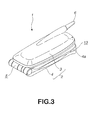
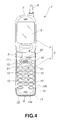
- FIGS. 1 to 4 shows a folding-type portable telephone employing the switching device according to the present invention, in which FIG. 1 is perspective view showing the portable telephone with upper and lower cases thereof being opened from each other, FIG. 2 is a perspective view of the portable telephone in FIG. 1 with the upper and lower cases being closed to each other, FIG. 3 is also a perspective view, from a direction different from that in FIG. 2, of the portable table in FIG. 1 with the upper and lower cases being closed to each other and FIG. 4 is a perspective view of the portable telephone in FIG. 1 with the upper and lower cases being opened from each other;
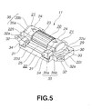
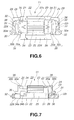
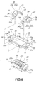
- FIGS. 5 to 9 show the switching device according to the present invention, in which FIG. 5 is a perspective view of the switching device, FIG. 6 is a front view of the switching device, FIG. 7 is a partially fragmentary bottom view of the switching device, FIG. 8 is an exploded perspective view of the switching device and FIG. 9 is an exploded perspective view, from a direction different from that in FIG. 8, of the switching device;
- FIGS. 10 and 11 shows the switching device being operated with a finger, in which FIG. 10 is a bottom view of the switching device, showing the central actuator being operated and FIG. 11 is a bottom view of the switching device, showing the finger being shifted from the central actuator to the outer actuator; and
- FIG. 12 is a bottom view of the switching device, showing the outer actuator being operated.
-
- It should be noted that in the embodiments of the switching device according to the present invention includes a jog dial of a portable telephone and two actuators disposed apart from a dial being the actuator of the jog dial on both its sides as shown in the accompanying drawings.
- First there will briefly be described the portable telephone as a handy electronic device employing the switching device according to the present invention.
- The portable telephone is generally indicated with a
reference 1. As shown, theportable telephone 1 includes abody case 2 formed from a synthetic resin and in which various members are housed and installed. - The
body case 2 consists of an upper half (will be referred to as "upper case" hereunder) 3 and lower half (will be referred to as "lower case" hereunder) 4. Theupper case 3 is hinged (indicated at reference 5) at the lower end thereof to the upper end of thelower case 4. The upper andlower cases lower cases upper case 3 abuts a part of the upper end of thelower case 4 to limit thecases - Provided at the top of the
upper case 3 is atelescopic antenna 6 via which theportable telephone 1 transmits and receives radio waves to and from a base station. - There is also provided in the upper front portion of the upper case 3 a
speaker 7 as an electroacoustic transducer which outputs a voice of the user of a destination telephone during conversation. - The
lower case 4 has provided in the lower front portion thereof amicrophone 8 which picks up a voice of the user of theportable telephone 1 during conversation. - Occupying the majority of the front surface area of the
upper case 3, a liquid crystal display (LCD) 9 is provided on theupper case 3 to display various pieces of information such as receiving condition of radio waves, remaining battery potential, telephone number of the one the user is talking with, contents of a telephone directory including destinations' phone numbers and names, etc., sending and reception history and other various kinds of registered data. - In the most area of the
lower case 4 except for the upper and lower front portions, there are disposedvarious operating keys 10 as input means. By pushing theseoperating keys 10, various commands and characters can be supplied to theportable telephone 1. - In the front upper portion of the
lower case 4, there is provided aswitching device 11 according to the present invention as another input means separately from theoperating keys 10. - Pushbutton switches 12 as still other input means are disposed to the right and left of and slightly away from the
switching device 11 on thelower case 4. - An
opening 4a is formed in the bottom end face and lower lateral sides of thelower case 4 and aprotective member 13 formed from elastomer is attached to cover thelower opening 4a from below and either lateral side of thelower case 4. - There is disposed inside the
lower opening 4a of thelower case 4 an interface connector (IF connector) 14 projecting slightly downward from thelower opening 4a. - An
earphone jack 15 is provided to the right lateral side of thelower opening 4a in a position slightly above the lower end of the opening 4a. - The
protective member 13 attached to the lower end of thelower case 4 covers thelower opening 4a of thelower case 4. It is shaped to have a sufficient size to cover theIF connector 14 as well. Also, theprotective member 13 has formed integrally therewith aconnector cover 13a which closes theIF connector 14 and anearphone jack cover 13b which closes theearphone jack 15. - The
switching device 11 includes ajog dial 20,operating button switches 21 located to the right and left of thejog dial 20, and arectangular frame 22 to support thejog dial 20 and right and leftoperating button switches 21 as one unit.Operating buttons 24 as actuators for theoperating button switches 21 are disposed in a right-left direction (will be referred to as "horizontal direction" hereunder) apart from adial 23 as an actuator for thejog dial 20 on both its sides. Note that thedial 23 of thejog dial 20 corresponds to a central actuator as defined in the scope of claim which will be set forth later while theoperating buttons 24 of theoperating button switches 21 correspond to the outer actuators defined also in the scope of claim. - The
jog dial 20 includes the abovecylindrical dial 23 and abase plate 25 formed from a relatively thick plate and having formed in the middle thereof a concavity in which a lower portion, equivalent to about 1/3 of, thedial 23 laid in horizontal position is received. Thebase plate 25 includes a pair ofspindle bearings 26 rotatably supporting the right and left ends of thedial 23, and also a horizontally (rightward and leftward) projectingtongue pieces 27 to fix thejog dial 20 to theframe 22 of theswitching device 11. Note that various contacts (not shown) are provided inside thebase plate 25 and encoders etc. are built in thespindle bearings 26. - By rotating the
dial 23 of thejog dial 20, it is possible to display, on theLCD 9, various options such as a menu, sending and reception history, telephone numbers list, etc. which can be scrolled for display, and an option selecting cursor, etc. - Also, by depressing the
jog dial 20 inwardly of thelower case 4, an option (process) displayed on theLCD 9 can be set or carried out. - Further, by operating the right or left
operating buttons switch 21, it is possible to select and carry out a predetermined option. For example, an option once set by pushing theoperating button switch 21 can be cleared. By pushing theoperating button switch 21, it is possible to raise a menu being displayed by one step in the menu hierarchy or to display a menu caught in the course of a conversation. - In the
jog dial 20,small projections 22a formed on the rear side of theframe 22 are fitted insmall holes 27a formed in thetongue pieces 27 of thebase plate 25 and joined at the free ends thereof to theframe 22 by heat-welding. - The
frame 22 consists offrame pieces dial positioning hole 28 defined by these frame pieces. Each of theframe pieces 22r and 221 at the right and left of thepositioning hole 28 has a relatively wideflat portion 29 having acircular contact 30 disposed thereon in a position slightly deviated upward from the center thereof. - Also, a projecting
pivot 31 is provided to project through each of the right and left end portions (near theflat portions 29, respectively) of the upper andlower frame pieces frame 22. The projectingpivot 31 is provided vertically correspondingly in position to each of thespindle bearings 26 of thebase plate 25 of thejog dial 20. - Note that the
pivot 31 corresponds to a pivot of the outer actuator defined in the scope of claim and "direction in which the three actuators are arrayed" defined inclaims lower case 4 in this embodiment. In short, the directions of thesepivots 31 are nearly perpendicular to the above horizontal direction and inward direction, namely, vertical directions. - An outward extending to-be-supported
piece 32 shaped like tongue piece is formed on the outer edge of each of the right andleft frame pieces 22r and 221 of theframe 22 and in a position slightly deviated downward from the center of the frame piece, and asmall hole 32a is formed in the to-be-supported piece 32. A small projection (not shown) formed on the rear side of the front half (not indicated with any reference) of thelower case 4 is inserted into thesmall hole 32a formed in each of the to-be-supported piece 32. Then, theswitching device 11 is installed in thelower case 4 by heat-welding, for example, of the free end of the small projection. Thedial 23 of thejog dial 20 andoperating button 24 of each of the right and leftoperating buttons switches 21 are projected from the front surface of thelower case 4. - Since the right and left operating buttons switches 21 of the
switching device 11 are designed similarly in shape to each other except for their horizontal (right-left) symmetry, only the left-sideoperating button switch 21 will be described and referred to simply as "operating button switch 21" hereunder. So, any further description will not be made of the right-sideoperating button switch 21 but the regions and parts of the rightoperating buttons switch 21 will only be indicated with the same references as those for the corresponding regions and parts of the leftoperating button switch 21. - The
operating button switch 21 includes anoperating button 24 designed to have a semi-cylindrical appearance closed at the top and bottom and right and left thereof, apressing piece 33 projected to the left from the rear edge of theoperating button 24 and positioned in an anterior part of theflat portion 29 of theframe 22, and to-be-supported pieces 34 projected upward and downward, respectively, from the front edge of theoperating button 24 and also projected at the front edges thereof towards the rear side of theoperating button 24. - The
operating button 24 is also designed to have a sufficient size to cover the front, top and bottom and left side of the spindle bearing 26 of thejog dial 20 from the side opposite to thedial 23. The front side, or top, of theoperating button 24 is an operatingsurface 35 which is to be pushed with a finger F as will further be described later. - The
pressing piece 33 has asmall convexity 36 formed on the rear side thereof in a position corresponding to the above-mentionedcircular contact 30. As will be described later, when theoperating button 24 is pushed, thesmall convexity 36 will press thecontact 30 to turn on theoperating button switch 21. - Each of the to-
be-supported pieces 34 has provided at the end portion thereof asmall piece 34a opposite to a one provided on the mating to-be-supported piece 34. Thesmall piece 34a has formed therein asmall hole 34b in which eachpivot 31 in theframe 22 is fitted, whereby theoperating button switch 21 is pivotally supported on theframe 22. Note that the present invention is not limited to this manner of pivotal supporting of theoperating button switch 21 but the small hole may be formed at theframe 22 while the button spindle may be provided at each to-be-supported piece 34, for such a pivotal supporting. - That is to say, the
operating button switch 21 is pivotally supported on theframe 22 in a position slightly deviated vertically and outwardly from the width of thedial 23 in the rotating direction (width in a direction perpendicular to the pivot). They are supported by means of each to-be-supported piece 34 to theframe 22. Thus, theoperating button switch 21 can easily be assembled with a reduced number of working steps. - The operating
surface 35 of theoperating button 24 is vertically circular, namely, upwardly convex, at the right portion thereof and has a circumference of a curvature equal to or smaller than that of the circumference of thedial 23. It includes a slopedportion 35a rising more to the front as it goes towards the left thereof and aflat portion 35b provided at the left end portion of the operatingsurface 35 and whose outward projection is not varied from end to end. - The term "sloped" of the sloped
portion 35a or "flat" of theflat portion 35b describes the edge line of theoperating button 24 as sloped or flat as viewed from below. Actually, the slopedportion 35a of the operatingsurface 35 is fanned out to the front as it goes leftward. - In this embodiment, the sloped
portion 35a has a slope gradually rising more starting at the middle of theoperating button 24 in the horizontal direction. However, the present invention is not limited to this structure of theoperating button 24 but a sloped surface may be formed starting at the end of theoperating button 24 near the side of thejog dial 20. - Supported pivotally on the
frame 22 as in the above, theoperating button switch 21 covers the spindle bearing 26 of thejog dial 20 in the space inside theoperating button 24. Thus, the right edge of the operatingsurface 35 is positioned near the left circumferential edge of thedial 23 of thejog dial 20. Also, thesmall convexity 36 formed on thepressing piece 33 of theoperating button switch 21 is in contact with or in vicinity of thecontact 30. - The switching
device 11 in which thejog dial 20 and operating button switches 21 are unified as in the above is installed to thelower case 4 from inside of the latter, and thedial 23 and right (left) operatingbutton 24 are disposed to project a little from the surface of thelower case 4. - Thus, for operating the
jog dial 20, thedial 23 thereof is rotated up or down with the pad of the finger F or depressed inwardly of thelower case 4. - For operating the right or left
operating button switch 21, the finger F placed on thedial 23 is moved to roll to the right or left and the operatingsurface 35 of theoperating button 24 is pushed with a portion of the finger F, a little deviated to the lateral side from the finger pad. Theoperating button switch 21 thus pushed is pivoted about thepivot 31, the outer portion thereof (pressing piece 33) is pushed inwardly of thelower case 4, and the projectingsmall convexity 36 provided on the rear side of thepressing piece 33 presses thecontact 30 on theframe 22 to turn on theoperating button switch 21. - At this time, the central axis of pivoting of the
operating button switch 21 will cross thesmall piece 34a of the to-be-supported piece 34 and the spindle bearing 26 of thedial 23. - As in the above, since the
operating button switch 21 is pivotally supported on theframe 22 by means of the vertically and outwardly projecting to-be-supported piece 34 in a position deviated vertically and outwardly from the width of thedial 23 in the direction of rotation (width in the direction perpendicular to the pivot), so the central axis of pivoting can be made relatively long and thus even when the finger pushing theoperating button switch 21 is inclined, theoperating button switch 21 can positively be pushed without occurrence of any "prying". Namely, the switchingdevice 11 according to the present invention can be said to have a good operability. - More specifically, if the finger pushing the
operating button switch 21 is inclined when the distance between points at which theoperating button switch 21 is pivotally supported is reduced, "prying" will develop in theoperating button switch 21, so that theoperating button switch 21 cannot be pushed positively in a desired direction. Owing to the relative long central axis about which theoperating button switch 21 is pivotable, however, such a "prying" will not take place, that is, theoperating button switch 21 can positively be pushed. - When the finger F placed on the
dial 23 is moved to the left or right to rotate thedial 23, the pad of the finger F is in contact with thedial 23 while the portion of the finger F pushing theoperating button 24 is moved outwardly to roll on, and in contact with, the slopedportion 35a of the operatingsurface 35. When the main portion of the finger F rides on theflat portion 35b of the operatingsurface 35, the force applied on theflat portion 35b inwardly to thelower case 4 increases so that theoperating button switch 21 will be pivoted and thesmall convexity 36 press thecontact 30. Therefore, theflat portion 35b of the operatingsurface 35 functions to make easier the operation of theoperating button switch 21. Otherwise, the force to pivot theoperating button switch 21 will not develop unless the finger F is moved rather long on the slopedportion 35a of the operatingsurface 35 to the right or left, with the result that theoperating button switch 21 cannot be operated very well. - For operating the right or left
operating button switch 21, the outer portion thereof (left end of the leftoperating button switch 21 or right end of the right operating buttons switch 21) is pushed. Thus, thedial 23 will not be pushed. Namely, two pushbuttons will not be pushed together. - More particularly, even if it is tried to push the end portion, near the
dial 23, of theoperating button 24, that portion cannot be pushed towards the rear side (inwardly of the lower case 4) since each of the right and left operating button switches 21 has the fulcrum of pivoting thereof (pivot 31) located at the side of thedial 23. Therefore, when trying to operate either of the operating button switches 21, the finger F going to push theoperating button switch 21 has already been away from thedial 23 or no force will be applied in at least a direction in which thedial 23 is pushed. Even if the finger F is in contact with thedial 23, the latter cannot be depressed towards the rear side (inwardly of the lower case 4) and thus two pushbuttons can be prevented from being pushed together. - This is also true for depressing the
dial 23 inwardly of thelower case 4. Namely, when the finger F is put in contact with either of the right and leftoperating buttons 24, thedial 23 can be depressed inwardly of thelower case 4 but theoperating button switch 21 will be blocked by thepivot 31 and thus will not be depressed inwardly of thelower case 4. That is, it can be avoided that two pushbuttons will be pushed together. - In the
above switching device 11, each of the actuators (dial 23 and operating buttons 24) should desirably be 15 mm to 25 mm in dimension in the direction in which they are arrayed. The reason for the above is that because of the geometry of theswitching device 11 according to the present invention in theportable telephone 1, the finger F of the user operating theactuators device 11 will show an easier operability. - It is assumed here for example that the switching
device 11 is designed to have a size of 20 mm. In this case, thedial 23 may be 9 mm in length while each of the operating button switches 21 may be 5.2 mm in length, the gap between thedial 23 andoperating button switch 21 be 0.3 mm, the slopedportion 35a of the operatingsurface 35 of theoperating button switch 21 be 4.3 mm and theflat portion 35b of the operatingsurface 35 may be 0.9 mm in length. - In addition, the horizontal dimension of the
switching device 11 can be determined according to the above-mentioned width of human being's finger F, but it is desirable to determine it taking the width of theportable telephone 1 in consideration. - In the
switching device 11, the two operating button switches 21 are disposed apart from thedial 23 on both its sides. However, since these three actuators (dial 23 and operating button switches 21) are disposed in vicinity of each other, the switchingdevice 11 can be used with an improved operability and the dimension of theswitching device 11 in the direction in which the three actuators are arrayed can be reduced. Therefore, by adopting theswitching device 11 according to the present invention, the terminals such as portable telephones can naturally be reduced in horizontal (right-left) dimension and also another switch, for example, the pushbutton switches 12 included in this embodiment can be disposed in the terminal. - Note that the shape and structure of each component included in the above embodiment are just examples to which the present invention is not limited, and thus the technological scope of the present invention should never be interpreted limitedly.
Claims (1)
- A switching device (11) including one central actuator (23) and two outer actuators (21) disposed apart from said central actuator, one on each side of said central actuator, wherein:said central actuator (23) is a cylindrical dial (23) supported rotatably about a pair of spindle bearings (26) of a base plate (25) and supported depressibly;said base plate (25) supporting said central actuator (23) is disposed fitted in a frame (22);each of said outer actuators (21) is pivotable about a pivot axis which is generally perpendicular to a direction in which the three actuators are arrayed and about a pivot axis generally perpendicular to a direction in which the operating surface of said outer actuator is to be pushed, to press a contact (30) disposed on the frame (22) when said outer actuator (21) is pivoted; andeach of said outer actuators (21) has a to-be-supported piece (34) extending to a position where said outer actuator (21) is deviated away from the lateral edge of the dial (23) in the rotating direction as viewed from front, and is pivotally supported at the end of the to-be-supported piece (34) to the frame (22) and thus it has a pivot axis crossing the spindle bearing of said central actuator.
Applications Claiming Priority (2)
| Application Number | Priority Date | Filing Date | Title |
|---|---|---|---|
| JP2000339125A JP4356911B2 (en) | 2000-11-07 | 2000-11-07 | Switch device |
| JP2000339125 | 2000-11-07 |
Publications (3)
| Publication Number | Publication Date |
|---|---|
| EP1206101A2 true EP1206101A2 (en) | 2002-05-15 |
| EP1206101A3 EP1206101A3 (en) | 2004-01-07 |
| EP1206101B1 EP1206101B1 (en) | 2006-01-11 |
Family
ID=18814235
Family Applications (1)
| Application Number | Title | Priority Date | Filing Date |
|---|---|---|---|
| EP01309397A Expired - Lifetime EP1206101B1 (en) | 2000-11-07 | 2001-11-06 | Switching device |
Country Status (6)
| Country | Link |
|---|---|
| US (1) | US6862459B2 (en) |
| EP (1) | EP1206101B1 (en) |
| JP (1) | JP4356911B2 (en) |
| KR (1) | KR100871925B1 (en) |
| CN (1) | CN1249746C (en) |
| DE (1) | DE60116579T2 (en) |
Cited By (3)
| Publication number | Priority date | Publication date | Assignee | Title |
|---|---|---|---|---|
| EP1574938A2 (en) | 2004-03-10 | 2005-09-14 | Samsung Electronics Co., Ltd. | A switch assembly |
| EP1826991A2 (en) | 2006-02-28 | 2007-08-29 | LG Electronics Inc. | Input device for an electronic device and electronic device having the same |
| US7996050B2 (en) | 2006-02-28 | 2011-08-09 | Lg Electronics Inc. | Input device for an electronic device and electronic device having the same |
Families Citing this family (23)
| Publication number | Priority date | Publication date | Assignee | Title |
|---|---|---|---|---|
| JP2004147279A (en) * | 2002-08-30 | 2004-05-20 | Fujitsu Ltd | Folding type electronic apparatus |
| JP3999092B2 (en) * | 2002-09-30 | 2007-10-31 | 京セラ株式会社 | Stackable mobile terminal device |
| JP2004320375A (en) * | 2003-04-15 | 2004-11-11 | Sony Ericsson Mobilecommunications Japan Inc | Electronic apparatus |
| US7088348B2 (en) * | 2003-07-14 | 2006-08-08 | Microsoft Corporation | Ergonomic pointing device |
| US7082323B2 (en) * | 2004-02-17 | 2006-07-25 | Speed Tech Corp. | Mobile navigation device |
| US7164891B2 (en) * | 2004-04-07 | 2007-01-16 | Speed Tech Corp. | Roller construction with a sense of feel for a mobile navigation device |
| US7145557B2 (en) * | 2004-06-09 | 2006-12-05 | Speed Tech Corp. | Roller construction with direction finding for a mobile navigation device |
| US7212834B2 (en) * | 2004-08-18 | 2007-05-01 | Speed Tech Corp. | Mobile device having an improved roller feel |
| US20060087492A1 (en) * | 2004-09-01 | 2006-04-27 | Speed Tech Corp. | Fixture device for a roller construction module |
| TWM277053U (en) * | 2005-03-18 | 2005-10-01 | Speed Tech Corp | Holder structure improvement of guiding devices |
| TWM276344U (en) * | 2005-04-08 | 2005-09-21 | Speed Tech Corp | Guiding instruction device |
| KR100675179B1 (en) * | 2005-05-16 | 2007-01-30 | 엘지전자 주식회사 | Scroll type input apparatus for mobile communication terminal |
| CN101026040A (en) * | 2006-02-18 | 2007-08-29 | 鸿富锦精密工业(深圳)有限公司 | Switch device |
| KR20080044729A (en) * | 2006-11-17 | 2008-05-21 | 엘지전자 주식회사 | Slide type mobile terminal |
| KR20080044728A (en) * | 2006-11-17 | 2008-05-21 | 엘지전자 주식회사 | Folder type mobile terminal |
| KR101223479B1 (en) * | 2006-11-17 | 2013-01-17 | 엘지전자 주식회사 | Mobile terminal having structure for preventing collision |
| US8019394B2 (en) * | 2007-06-29 | 2011-09-13 | Motorola Mobility, Inc. | Component packaging for handheld communication devices |
| TWM329848U (en) * | 2007-09-20 | 2008-04-01 | Speed Tech Corp | Electrical navigation device |
| US20090170571A1 (en) * | 2007-12-31 | 2009-07-02 | Motorola, Inc. | Method and apparatus for partial flip-open assist of ultra thin clam communication devices |
| US8204560B2 (en) * | 2008-12-17 | 2012-06-19 | Motorola Mobility, Inc. | Clamshell phone with edge access |
| US8508480B2 (en) * | 2009-01-09 | 2013-08-13 | Research In Motion Limited | Method and apparatus to facilitate non-flush general navigation buttons for a clamshell handheld device |
| US8681131B2 (en) * | 2009-06-29 | 2014-03-25 | Nokia Corporation | Method and apparatus for an electronic device assembly |
| US8611078B2 (en) * | 2010-12-29 | 2013-12-17 | Nokia Corporation | Method and apparatus for displays |
Citations (4)
| Publication number | Priority date | Publication date | Assignee | Title |
|---|---|---|---|---|
| US4992631A (en) * | 1989-06-02 | 1991-02-12 | Atari Corporation | Multi-directional switch assembly |
| EP0901262A2 (en) * | 1997-09-04 | 1999-03-10 | Nokia Mobile Phones Ltd. | Menu navigation key for a portable telephone |
| EP1004957A1 (en) * | 1998-03-05 | 2000-05-31 | Mitsubishi Denki Kabushiki Kaisha | Portable terminal |
| US6137477A (en) * | 1998-08-11 | 2000-10-24 | Hu; Ken-Pei | Encoder wheel assembly |
Family Cites Families (1)
| Publication number | Priority date | Publication date | Assignee | Title |
|---|---|---|---|---|
| GB2330981B (en) * | 1997-10-31 | 2002-07-03 | Nokia Mobile Phones Ltd | A radiotelephone handset |
-
2000
- 2000-11-07 JP JP2000339125A patent/JP4356911B2/en not_active Expired - Fee Related
-
2001
- 2001-11-02 US US10/002,237 patent/US6862459B2/en not_active Expired - Fee Related
- 2001-11-05 KR KR1020010068663A patent/KR100871925B1/en not_active IP Right Cessation
- 2001-11-06 EP EP01309397A patent/EP1206101B1/en not_active Expired - Lifetime
- 2001-11-06 DE DE60116579T patent/DE60116579T2/en not_active Expired - Lifetime
- 2001-11-07 CN CNB011338822A patent/CN1249746C/en not_active Expired - Fee Related
Patent Citations (4)
| Publication number | Priority date | Publication date | Assignee | Title |
|---|---|---|---|---|
| US4992631A (en) * | 1989-06-02 | 1991-02-12 | Atari Corporation | Multi-directional switch assembly |
| EP0901262A2 (en) * | 1997-09-04 | 1999-03-10 | Nokia Mobile Phones Ltd. | Menu navigation key for a portable telephone |
| EP1004957A1 (en) * | 1998-03-05 | 2000-05-31 | Mitsubishi Denki Kabushiki Kaisha | Portable terminal |
| US6137477A (en) * | 1998-08-11 | 2000-10-24 | Hu; Ken-Pei | Encoder wheel assembly |
Cited By (7)
| Publication number | Priority date | Publication date | Assignee | Title |
|---|---|---|---|---|
| EP1574938A2 (en) | 2004-03-10 | 2005-09-14 | Samsung Electronics Co., Ltd. | A switch assembly |
| EP1574938A3 (en) * | 2004-03-10 | 2006-07-26 | Samsung Electronics Co., Ltd. | A switch assembly |
| EP1826991A2 (en) | 2006-02-28 | 2007-08-29 | LG Electronics Inc. | Input device for an electronic device and electronic device having the same |
| DE102007003270B4 (en) * | 2006-02-28 | 2008-07-31 | Lg Electronics Inc. | Mobile terminal |
| US7860538B2 (en) | 2006-02-28 | 2010-12-28 | Lg Electronics Inc. | Mobile terminal |
| US7996050B2 (en) | 2006-02-28 | 2011-08-09 | Lg Electronics Inc. | Input device for an electronic device and electronic device having the same |
| EP1826991A3 (en) * | 2006-02-28 | 2011-09-07 | LG Electronics Inc. | Input device for an electronic device and electronic device having the same |
Also Published As
| Publication number | Publication date |
|---|---|
| US20020086698A1 (en) | 2002-07-04 |
| DE60116579T2 (en) | 2006-12-07 |
| DE60116579D1 (en) | 2006-04-06 |
| CN1249746C (en) | 2006-04-05 |
| JP4356911B2 (en) | 2009-11-04 |
| KR20020035752A (en) | 2002-05-15 |
| JP2002150895A (en) | 2002-05-24 |
| US6862459B2 (en) | 2005-03-01 |
| CN1354486A (en) | 2002-06-19 |
| EP1206101B1 (en) | 2006-01-11 |
| KR100871925B1 (en) | 2008-12-05 |
| EP1206101A3 (en) | 2004-01-07 |
Similar Documents
| Publication | Publication Date | Title |
|---|---|---|
| EP1206101B1 (en) | Switching device | |
| US6768899B2 (en) | Rotational mechanism for a wireless communication device | |
| JP4302024B2 (en) | Button structure, portable electronic device | |
| KR20010098792A (en) | Rotatively-operated switch apparatus and communication terminal apparatus | |
| JPH11126126A (en) | Scroll switch device for portable telephone set | |
| US7700886B2 (en) | Rubber key device | |
| EP1926115B1 (en) | Two-way key of portable terminal | |
| WO2002039471A1 (en) | Switch device | |
| JP4213019B2 (en) | Multi-directional input device | |
| US20070123320A1 (en) | Key input device for portable terminal | |
| EP1924056B1 (en) | Folding type mobile terminal | |
| US6751312B1 (en) | Knob for covering a top end of a pointing stick of a stick switch, stick switch, and portable electronic device and portable telephone comprising the stick switch | |
| JP2002358155A (en) | Input device | |
| JP4313630B2 (en) | Key input device | |
| JP2004502348A (en) | Navigation selection device for various functions of electronic devices | |
| KR100618124B1 (en) | Navigating assembley Mobile terminal and Mobile terminal having thereof | |
| JP2001189780A (en) | Portable communication terminal and key pad for portable communication terminal | |
| JP2002190238A (en) | Structure of cursor key button | |
| JP2002056749A (en) | Keyboard switch | |
| JP2000123689A (en) | Operating button of electronic apparatus | |
| JP2000090780A (en) | Multifunction key |
Legal Events
| Date | Code | Title | Description |
|---|---|---|---|
| PUAI | Public reference made under article 153(3) epc to a published international application that has entered the european phase |
Free format text: ORIGINAL CODE: 0009012 |
|
| AK | Designated contracting states |
Kind code of ref document: A2 Designated state(s): AT BE CH CY DE DK ES FI FR GB GR IE IT LI LU MC NL PT SE TR |
|
| AX | Request for extension of the european patent |
Free format text: AL;LT;LV;MK;RO;SI |
|
| PUAL | Search report despatched |
Free format text: ORIGINAL CODE: 0009013 |
|
| AK | Designated contracting states |
Kind code of ref document: A3 Designated state(s): AT BE CH CY DE DK ES FI FR GB GR IE IT LI LU MC NL PT SE TR |
|
| AX | Request for extension of the european patent |
Extension state: AL LT LV MK RO SI |
|
| RIC1 | Information provided on ipc code assigned before grant |
Ipc: 7H 04M 1/247 B Ipc: 7H 04M 1/02 A |
|
| 17P | Request for examination filed |
Effective date: 20040329 |
|
| 17Q | First examination report despatched |
Effective date: 20040429 |
|
| AKX | Designation fees paid |
Designated state(s): DE FR GB |
|
| GRAP | Despatch of communication of intention to grant a patent |
Free format text: ORIGINAL CODE: EPIDOSNIGR1 |
|
| GRAS | Grant fee paid |
Free format text: ORIGINAL CODE: EPIDOSNIGR3 |
|
| GRAA | (expected) grant |
Free format text: ORIGINAL CODE: 0009210 |
|
| AK | Designated contracting states |
Kind code of ref document: B1 Designated state(s): DE FR GB |
|
| REF | Corresponds to: |
Ref document number: 60116579 Country of ref document: DE Date of ref document: 20060406 Kind code of ref document: P |
|
| ET | Fr: translation filed | ||
| PLBE | No opposition filed within time limit |
Free format text: ORIGINAL CODE: 0009261 |
|
| STAA | Information on the status of an ep patent application or granted ep patent |
Free format text: STATUS: NO OPPOSITION FILED WITHIN TIME LIMIT |
|
| 26N | No opposition filed |
Effective date: 20061012 |
|
| PGFP | Annual fee paid to national office [announced via postgrant information from national office to epo] |
Ref country code: DE Payment date: 20101104 Year of fee payment: 10 |
|
| PGFP | Annual fee paid to national office [announced via postgrant information from national office to epo] |
Ref country code: GB Payment date: 20101103 Year of fee payment: 10 |
|
| PGFP | Annual fee paid to national office [announced via postgrant information from national office to epo] |
Ref country code: FR Payment date: 20111130 Year of fee payment: 11 |
|
| GBPC | Gb: european patent ceased through non-payment of renewal fee |
Effective date: 20121106 |
|
| REG | Reference to a national code |
Ref country code: FR Ref legal event code: ST Effective date: 20130731 |
|
| REG | Reference to a national code |
Ref country code: DE Ref legal event code: R119 Ref document number: 60116579 Country of ref document: DE Effective date: 20130601 |
|
| PG25 | Lapsed in a contracting state [announced via postgrant information from national office to epo] |
Ref country code: DE Free format text: LAPSE BECAUSE OF NON-PAYMENT OF DUE FEES Effective date: 20130601 |
|
| PG25 | Lapsed in a contracting state [announced via postgrant information from national office to epo] |
Ref country code: GB Free format text: LAPSE BECAUSE OF NON-PAYMENT OF DUE FEES Effective date: 20121106 Ref country code: FR Free format text: LAPSE BECAUSE OF NON-PAYMENT OF DUE FEES Effective date: 20121130 |