EP1206082A1 - Apparatus for processing packet, and medium storing packet processing program - Google Patents
Apparatus for processing packet, and medium storing packet processing program Download PDFInfo
- Publication number
- EP1206082A1 EP1206082A1 EP00949952A EP00949952A EP1206082A1 EP 1206082 A1 EP1206082 A1 EP 1206082A1 EP 00949952 A EP00949952 A EP 00949952A EP 00949952 A EP00949952 A EP 00949952A EP 1206082 A1 EP1206082 A1 EP 1206082A1
- Authority
- EP
- European Patent Office
- Prior art keywords
- data
- packets
- control means
- receiving buffer
- reproduction
- Prior art date
- Legal status (The legal status is an assumption and is not a legal conclusion. Google has not performed a legal analysis and makes no representation as to the accuracy of the status listed.)
- Granted
Links
Images







Classifications
-
- H—ELECTRICITY
- H04—ELECTRIC COMMUNICATION TECHNIQUE
- H04L—TRANSMISSION OF DIGITAL INFORMATION, e.g. TELEGRAPHIC COMMUNICATION
- H04L12/00—Data switching networks
-
- H—ELECTRICITY
- H04—ELECTRIC COMMUNICATION TECHNIQUE
- H04L—TRANSMISSION OF DIGITAL INFORMATION, e.g. TELEGRAPHIC COMMUNICATION
- H04L12/00—Data switching networks
- H04L12/64—Hybrid switching systems
- H04L12/6418—Hybrid transport
-
- H—ELECTRICITY
- H04—ELECTRIC COMMUNICATION TECHNIQUE
- H04J—MULTIPLEX COMMUNICATION
- H04J3/00—Time-division multiplex systems
- H04J3/02—Details
- H04J3/06—Synchronising arrangements
- H04J3/062—Synchronisation of signals having the same nominal but fluctuating bit rates, e.g. using buffers
- H04J3/0632—Synchronisation of packets and cells, e.g. transmission of voice via a packet network, circuit emulation service [CES]
-
- H—ELECTRICITY
- H04—ELECTRIC COMMUNICATION TECHNIQUE
- H04L—TRANSMISSION OF DIGITAL INFORMATION, e.g. TELEGRAPHIC COMMUNICATION
- H04L7/00—Arrangements for synchronising receiver with transmitter
-
- H—ELECTRICITY
- H04—ELECTRIC COMMUNICATION TECHNIQUE
- H04L—TRANSMISSION OF DIGITAL INFORMATION, e.g. TELEGRAPHIC COMMUNICATION
- H04L12/00—Data switching networks
- H04L12/64—Hybrid switching systems
- H04L12/6418—Hybrid transport
- H04L2012/6481—Speech, voice
-
- H—ELECTRICITY
- H04—ELECTRIC COMMUNICATION TECHNIQUE
- H04L—TRANSMISSION OF DIGITAL INFORMATION, e.g. TELEGRAPHIC COMMUNICATION
- H04L12/00—Data switching networks
- H04L12/64—Hybrid switching systems
- H04L12/6418—Hybrid transport
- H04L2012/6489—Buffer Management, Threshold setting, Scheduling, Shaping
Definitions
- the present invention relates to a packet processor and a recording medium with packet processing programs thereon, which are suitable for terminals and gateway devices for communicating voice and music by way of packet-based networks such as the Internet, etc.
- Voice communication services represented by telephone, have been conventionally offered by telephone communications companies establishing communications networks on their own accounts.
- Fig.13 shows an example of a communications network for offering conventional telephone services.
- the telephone network is comprised of regional centers 801 at the topmost layer, primary centers 802 connected to one regional center, toll centers 803 and terminal offices 804, each of which is connected to subscribers 805 as the users.
- Regional centers 801 form mesh networks while primary centers 802, toll centers 803 and terminal offices 804 form star-like networks.
- each of the centers and offices has an exchange, and when a transmission link needs to be established between exchanges, line switching is performed by time division multiplex system of the communication band necessary for the connection.
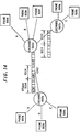
- Fig.14 shows the concept of line switching based on time division multiplex system.
- a telephone 1001 used by a user is connected to an exchange 1002.
- a transmission path 1003 having a predetermined band is provided to connect between the exchanges.
- the calls among a plurality of telephones 1001a to 1001h are realized through the transmission paths based on time division multiplex system. It is understood from Fig.14 that calls are established between phone 1001a and phone 1001d, phone 1001b and phone 1001e, and phone 1001c and phone 1001h while the transmission path between the exchanges still has empty areas.
- time division multiplex system since a multiple number of signals to be exchanged between terminals are multiplexed using frames 1004 each having a predetermined period unit, the band for a call once established between terminals will be secured until the call terminates.
- the unit of frame 1004 of division multiplexing is typically 8 KHz (125 ⁇ sec.). Since this relation is held for all the connected exchanges, there is no need to pay attention to synchronization between the terminals if each telephone terminal transmits and receives data based on this signal.
- Fig.15 shows an example of communications among PCs over the Internet.
- PCs 904a and 904b connected within an intranet 901 is connected to the Internet 905 at an Internet provider 903a by way of a router or gateway 902.
- Ordinary users of PCs 904c and 904d access to the Internet 905 by way of Internet Providers 903b and 903c using the telephone line via PPP.
- Fig.16 shows the concept for routing data on the Internet.
- Each terminal monitors the status of the network and sends out packets having a destination address (IP address) attached thereon onto the network when the network has any empty channel.
- IP address IP address
- Packets from terminals connected to the network are checked as to their IP addresses and routed by routers so that they will be transferred to the routers that are located nearest to their destinations. The packets are thus transferred to those routers, where they are checked as to their addresses, and further, transferred to associated terminals.
- data communication through the Internet by routing makes it possible to transmit and receive data as long as there is an empty channel allowing for packet transmission on the network, so that a large amount of data can be communicated at low cost.
- router 1103a sends out packets 1102a and 1102b in the order in which they reached it. No jitter will arise if the packets from each terminal just fit in the transmission intervals between the packets from the other terminal. However, if two packets are sent out at almost the same timing, the packet which has first arrived at router 1103a is processed first while the packet from the other terminal is kept waiting during that time.
- packets 1102a are sent out to router 1103a at intervals of period 1104a while packets 1102b are sent out at intervals of period 1104b.
- Router 1103a processes the packets and sends them out to the router 1103b in the order in which they reached it.
- packet 1102b and then packet 1102a are processed. Therefore, packet 1102a is kept waiting from its arrival until the process of packet 1102b is completed.
- the transmission intervals become different from those at which the packets were send out from PC1101a and 1101b.
- packets 1102a and 1102b are separated and sent out to respective destinations PC1101c and 1101d. That is, the transmission interval of packets 1102a changes from 1104a to 1104c and the transmission interval of packets 1102b changes from 1104b to 1104d, which will cause jitter.
- packet communication such as through the Internet causes packet jitter due to routing over the network.
- packet jitter occurs, voice sound comes in with breaks in the case of IP phone, for example.
- a buffer is provided on the receiver side so that data can be reproduced after a certain amount of data has been stored.
- breaks occur if the buffer has a lower storage capacity whereas delay increases if the buffer has a higher storage capacity, degrading the characteristics of conversation on IP phone.
- a transmitting terminal 1202a is comprised of a microphone 1211, an A/D converting circuit 1212, an encoder circuit 1213, a network interface 1214a while a receiving terminal 1202b is comprised of a network interface 1214b, a decoder circuit 1215, an D/A converting circuit 1216 and a speaker 1217.
- each terminal since each terminal does not operate in synchronism with the clock on the network as in a line exchange configuration, individual terminals operate in accordance with their own clocks 1201a and 1201b, respectively.
- clock rate for sampling voice sound between the transmitter side and receiver side, data overflow or underflow will occur on the receiver side.
- This method is markedly effective as a method of sending a reference clock to a destination terminal by packet communication having no common clock, but needs to provide a 27 MHz clock on the transmitter side and a high-precision PLL on the receiver side, which are too expensive to be provided for PCs and the like. Further, it is necessary for this method to send an exact PCR from the transmitter side, and this method is not effective for connection with a terminal which cannot send this information exactly.
- the present invention is configured as follows:
- the first invention is a packet processor for processing packets of data received via a network to reproduce the data, comprising: a receiving buffer for storing received packets; a reproducing means for reproducing data of the packets based on a reproduction clock; and a control means for performing control so as to reproduce data without breaks, and is characterized in that the control means controls the packets having been stored in the receiving buffer by their number, holds a reference value for the number of received packets, which is determined beforehand, and causes the reproducing means to start data reproduction when the number of packets exceeds the reference number.
- the second invention is the packet processor defined in the first invention, wherein the control means monitors the state of the receiving buffer and collects, when the data in the buffer is used up, data up to the level corresponding to the reference value before causing the reproducing means to restart data reproduction.
- the third invention is the packet processor defined in the first invention, wherein the control means monitors the state of the receiving buffer and discards, when the data in the buffer exceeds the predetermined buffer size, a fixed amount of data from the buffer.
- the fourth invention is the packet processor defined in the first invention, wherein the control means monitors the state of the receiving buffer and modifies, when the data in the buffer is used up, the reference value for the number of received packet at which reproduction of data is started, upon the next reproduction of data.
- the fifth invention is the packet processor defined in the first invention, wherein the control means monitors the state of the receiving buffer and modifies, when the data in the buffer exceeds the predetermined buffer size, the size of the receiving buffer.
- the sixth invention is the packet processor defined in any one of the second through fifth inventions, wherein the control means monitors the number of packets in the receiving buffer at intervals of a predetermined time period, and when the result shows increase or decrease in the number of packets with time, the control means, based on the result, modifies the receiving buffer size and the reference value for the number of received packets at which reproduction of data is started.
- the seventh invention is the packet processor defined in any one of the second through fifth inventions, wherein the control means monitors the number of packets in the receiving buffer at intervals of a predetermined time period, and when the result shows increase or decrease in the number of packets with time, the control means, based on the result, modifies the clock for data reproduction.
- the eighth invention is the packet processor defined in the fourth or fifth invention, wherein the control means records the modifications of the reference value for the number of received packets or the receiving buffer size, continuously from the start of the communication, and if modifications of one type successively occur, the control means, based on the result, modifies the receiving buffer size and the reference value for the number of received packets at which reproduction of data is started.
- the ninth invention is the packet processor defined in the fourth or fifth invention, wherein the control means records the modifications of the reference value for the number of received packets or the receiving buffer size, continuously from the start of the communication, and if modifications of one type successively occur, the control means, based on the result, modifies the clock for data reproduction.
- the tenth invention is a recording medium holding a packet processing program for use in a packet processor for processing packets of data received via a network to reproduce the data
- the packet processor comprises a receiving buffer for storing received packets; a reproducing means for reproducing data of the packets based on a reproduction clock; and a control means for performing control so as to reproduce data without breaks
- the packet processing program is characterized in that the control means is adapted to control the packets having been stored in the receiving buffer by their number, hold with a reference value for the number of received packets, which is determined beforehand, and cause the reproducing means to start data reproduction when the number of packets exceeds the reference value.
- the eleventh invention is the recording medium holding a packet processing program defined in the tenth invention, wherein the control means is adapted to monitor the state of the receiving buffer and collect, when the data in the buffer is used up, data up to the level corresponding to the reference value before causing the reproducing means to restart data reproduction.
- the twelfth invention is the recording medium holding a packet processing program defined in the tenth invention, wherein the control means is adapted to monitor the state of the receiving buffer and discard, when the data in the buffer exceeds the predetermined buffer size, a fixed amount of data from the buffer.
- the thirteenth invention is the recording medium holding a packet processing program defined in the tenth invention, wherein the control means is adapted to monitor the state of the receiving buffer and modify, when the data in the buffer is used up, the reference value for the number of received packet at which reproduction of data is started, upon the next reproduction of data.
- the fourteenth invention is the recording medium holding a packet processing program defined in the tenth invention, wherein the control means is adapted to monitor the state of the receiving buffer and modify, when the data in the buffer exceeds the predetermined buffer size, the size of the receiving buffer.
- the fifteenth invention is the recording medium holding a packet processing program defined in any one of the eleventh through fourteenth inventions, wherein the control means is adapted to monitor the number of packets in the receiving buffer at intervals of a predetermined time period and when the result shows increase or decrease in the number of packets with time, the control means is operated to modify, based on the result, the receiving buffer size and the reference value for the number of received packets at which reproduction of data is started.
- the sixteenth invention is the recording medium holding a packet processing program defined in any one of the eleventh through fourteenth inventions, wherein the control means is adapted to monitor the number of packets in the receiving buffer at intervals of a predetermined time period and when the result shows increase or decrease in the number of packets with time, the control means is operated to modify, based on the result, the clock for data reproduction.
- the seventeenth invention is the recording medium holding a packet processing program defined in the thirteenth or fourteenth invention, wherein the control means is adapted to record the modifications of the reference value for the number of received packets or the receiving buffer size, continuously from the start of the communication, and if modifications of one type successively occur, the control means is operated to modify, based on the result, the receiving buffer size and the reference value for the number of received packets at which reproduction of data is started.
- the eighteenth invention is the recording medium holding a packet processing program defined in the thirteenth or fourteenth invention, wherein the control means is adapted to record the modifications of the reference value for the number of received packets or the receiving buffer size, continuously from the start of the communication, and if modifications of one type successively occur, the control means is adapted to modify, based on the result, the clock for data reproduction.
- the packet processor of the present invention provides a simple method which can realize receiving buffer control for reproducing data such as voice sound, music etc., in an optimal way by absorbing packet jitter which varies over time depending on the network status. Since none of the temporal information from the transmitting side, which has been used in the conventional configuration, is used in the packet processor of the present invention, the optimal control can be achieved on the receiving side only.
- difference in reference clocks between the terminal ends which may cause a problem in packet communication, can be detected by only monitoring the status of the receiving buffer at regular intervals or when a particular event has occurred, it is possible to modify the difference in a simple, low-cost method without the necessity of a complex, expensive PLL circuit and/or high-precision reference clock.
- Fig.1 is a block diagram showing a communication system made up of voice packet communication apparatuses of the present invention
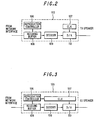
- Fig.2 is block diagram showing a voice processor used this communication apparatus
- Fig.3 is a block diagram showing another voice processor used in this communication apparatus
- Fig.4 is an illustrative view showing the operation of a receiving buffer
- Fig.5 is a flowchart for illustrating the operation of a reproduction controller controlling a receiving buffer
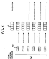
- Fig.6 is an illustrative view showing the states of a receiving buffer in a time-sequential manner
- Fig.7 is an illustrative view showing the state of received packets and a receiving buffer in a time-sequential manner
- Fig.8 is an illustrative view showing another state of received packets and a receiving buffer in a time-sequential manner
- Fig.9 is a flowchart for illustrating a method of detecting the difference between reference clocks on terminal ends
- Fig.10
- Fig.1 is a block diagram showing a communication system of voice packet communication apparatus of the present invention
- Figs.2 and 3 are block diagrams showing voice processors used in this communication system.
- the communication system shown in Fig.1 comprises voice packet communication apparatus 100a and 100b and the Internet 105.
- Voice packet communication apparatus (terminal units) 100a and 100b are comprised of microphones 101a and 101b, speakers 102a and 102b, voice processors 103a and 103b serving as packet processors and network interfaces 104a and 104b.
- a voice sound input through microphone 101a is A/D converted through voice processor 103a and encoded as required, then packetized so that the packets are transmitted from network interface 104a to terminal unit 100b by way of Internet 105.
- the packets sent out from terminal unit 100a are processed through network interface 104b and buffered in voice processor 103b, then decoded as required, and D/A converted so as to be output from speaker 102b.
- Figs.2 and 3 show a configuration for controlling the receiving buffer to reproduce voice data in an optimal way so as to absorb the jitter.
- Fig.3 shows a configuration for modifying the clock for reproduction based on the state of the receiving buffer so as to absorb the difference in clocks between terminal ends.
- Voice processor 103 comprises a reproduction controller 106, a clock generator 107, a receiving buffer 108, a decoder 109 and a D/A converter 110. Decoder 109 and D/A converter 110 function as a data reproducing means to reproduce data in packets.
- Fig.2 packets received from network interface 104 are stored into receiving buffer 108.
- Reproduction controller 106 checks the state of receiving buffer 108 and performs a reproduction process mentioned below.
- the data in receiving buffer 108 is transferred to decoder 109 in accordance with instruction from reproduction controller 106 and decoded as voice sound, D/A converted by D/A converter 110 and then output as voice sound from speaker 102.
- the clock for D/A conversion is supplied from a reproduction clock CLK 107.
- Fig.3 shows a configuration which, in addition to the control shown in Fig.2, decodes voice sound by modifying the frequency of reproduction clock CLK 107 in accordance with instruction from reproduction controller 106 so that data of received packets to be reproduced will not cause overflow or underflow.
- Fig.4 is an illustrative view showing the operation of the receiving buffer.
- Fig.5 is a flowchart for illustrating the operation of the reproduction controller.
- N designates the size of receiving buffer 108
- n designates the reference value for received packets at which the received data starts to be reproduced
- x designates the number of packets in receiving buffer 108.
- Packets 201 sent from network interface 104 are temporarily stored into receiving buffer 108, and transferred to decoder 109 in accordance with instruction from reproduction controller 106 so that the data is reproduced.
- reproduction of data is started (S302).
- Fig.6 is an illustrative view showing the state of the receiving buffer in a time-sequential manner.
- the operation should be started with n set at a value as small as 1 or 2 if the condition of the network is unknown. If the value which would cause jitter can be predicated beforehand, the initial value of n should be determined based on that value.
- S305 stopping reproduction
- S301 reproduction is started.
- the state of receiving buffer 108 in this case is shown in Fig.4(b).
- n is incremented when receiving buffer 108 has become empty.
- Fig.4(c) shows the state of receiving buffer 108 in this situation. It is understood that packets are discarded and the receiving buffer size N is incremented after the buffer has become full.
- the reproduction control of the receiving buffer as above enables suitable reproduction control based on the number of received packets even if an overflow or underflow arises due to network-induced jitter or difference in reference clocks between terminal ends.
- Fig.9 is a flowchart for illustrating a method of detecting the difference in reference clocks between terminal ends, used in the present invention.
- Fig.10 shows illustrative charts for showing an example of the determining method when the state of the receiving buffer is monitored every fixed period.
- Reproduction controller 106 monitors the number of packets in receiving buffer 108 every fixed period(S401) and plots the number (S402).
- Fig.10 illustrates the plot results and the determining method. In Fig.10(a), though the packet count x is found to vary to some extent, this variation is attributed to network induced jitter, so that it is possible to determine that no difference in frequency between the terminal ends.
- Fig.10(b) shows decrease in the number of packets in the buffer due to frequency difference in addition to the variation due to jitter.
- Fig.10(c) shows increase in the number of packets in the buffer due to frequency difference in addition to the variation due to jitter.
- the plot starts from zero in the horizontal axis as shown in Figs.7 and 8 and increases by one every occurrence of an event.
- Fig.12(a) The plot result and the determining method are shown in Fig.7.
- Fig.12(b) no particular tendency is found as to occurrence of the events, and the occurrence of the events can be attributed to network induced jitter. Hence, it can be determined that there is no difference in frequency between the terminal ends.
- Fig.12(b) it is understood that there is a tendency toward underflow due to difference in frequency in addition to the fluctuation caused by jitter.
- Fig.12(c) it is understood that there is a tendency toward overflow due to difference in frequency in addition to the fluctuation caused by jitter.
- the difference in frequency between the terminal ends may be corrected by changing the value 'n', modifying the frequency of the reference clock, or adjusting both in the same manner as described with reference to Figs.9 and 10.
- a packet processor of the present invention provides a simple method which can realize reception buffer control for reproducing data such as voice sound etc., in an optimal way by absorbing packet jitter which varies over time depending on the network status. Since non of temporal information from the transmitting side, which has been used in the conventional configuration, is used in the method of the present invention, the optimal control can be achieved on the receiving side only.
- difference in reference clocks between the terminal ends which may cause a problem in packet communication, can be detected by only monitoring the status of the receiving buffer when a particular event has occurred, it is possible to modify the difference in a simple, low-cost method without the necessity of a complex, expensive PLL circuit and/or high-precision reference clock.
- the packet processor according to the present invention is suitable for use with terminals and gateways which communicate voice sound and music over a packet-based network such as the Internet.
Landscapes
- Engineering & Computer Science (AREA)
- Computer Networks & Wireless Communication (AREA)
- Signal Processing (AREA)
- Multimedia (AREA)
- Computer Hardware Design (AREA)
- Data Exchanges In Wide-Area Networks (AREA)
- Synchronisation In Digital Transmission Systems (AREA)
Abstract
Description
Claims (18)
- A packet processor for processing packets of data received via a network to reproduce the data, comprising:wherein the control means controls the packets having been stored in the receiving buffer by their number, holds a reference value for the number of received packets, which is determined beforehand, and causes the reproducing means to start data reproduction when the number of packets exceeds the reference number.a receiving buffer for storing received packets;a reproducing means for reproducing data of the packets based on a reproduction clock; anda control means for performing control so as to reproduce data without breaks,
- The packet processor according to claim 1, wherein the control means monitors a state of the receiving buffer and collects, when the data in the buffer is used up, data up to a level corresponding to the reference value before causing the reproducing means to restart data reproduction.
- The packet processor according to claim 1, wherein the control means monitors a state of the receiving buffer and discards, when the data in the buffer exceeds a predetermined buffer size, a fixed amount of data from the buffer.
- The packet processor according to claim 1, wherein the control means monitors a state of the receiving buffer and modifies, when the data in the buffer is used up, the reference value for the number of received packet at which reproduction of data is started, upon a next reproduction of data.
- The packet processor according to claim 1, wherein the control means monitors a state of the receiving buffer and modifies, when the data in the buffer exceeds a predetermined buffer size, the size of the receiving buffer.
- The packet processor according to any one of claims 2 through 5, wherein the control means monitors the number of packets in the receiving buffer at intervals of a predetermined time period, and when a result shows increase or decrease in the number of packets with time, the control means, based on the result, modifies the receiving buffer size and the reference value for the number of received packets at which reproduction of data is started.
- The packet processor according to any one of claims 2 through 5, wherein the control means monitors the number of packets in the receiving buffer at intervals of a predetermined time period, and when a result shows increase or decrease in the number of packets with time, the control means, based on the result, modifies a clock for data reproduction.
- The packet processor according to claim 4 or 5, wherein the control means records the modifications of the reference value for the number of received packets or the receiving buffer size, continuously from a start of a communication, and if modifications of one type successively occur, the control means, based on the result, modifies the receiving buffer size and the reference value for the number of received packets at which reproduction of data is started.
- The packet processor according to claim 4 or 5, wherein the control means records the modifications of the reference value for the number of received packets or the receiving buffer size, continuously from a start of a communication, and if modifications of one type successively occur, the control means, based on the result, modifies a clock for data reproduction.
- A recording medium holding a packet processing program for use in a packet processor for processing packets of data received via a network to reproduce the data, wherein the packet processor comprises a receiving buffer for storing received packets; a reproducing means for reproducing data of the packets based on a reproduction clock; and a control means for performing control so as to reproduce data without breaks, and
wherein the packet processing program is characterized in that the control means is adapted to control the packets having been stored in the receiving buffer by their number, hold with a reference value for the number of received packets, which is determined beforehand, and cause the reproducing means to start data reproduction when the number of packets exceeds the reference value. - The recording medium holding a packet processing program according to claim 10, wherein the control means is adapted to monitor a state of the receiving buffer and collect, when the data in the buffer is used up, data up to a level corresponding to the reference value before causing the reproducing means to restart data reproduction.
- The recording medium holding a packet processing program according to claim 10, wherein the control means is adapted to monitor a state of the receiving buffer and discard, when the data in the buffer exceeds a predetermined buffer size, a fixed amount of data from the buffer.
- The recording medium holding a packet processing program according to claim 10, wherein the control means is adapted to monitor a state of the receiving buffer and modify, when the data in the buffer is used up, the reference value for the number of received packet at which reproduction of data is started, upon a next reproduction of data.
- The recording medium holding a packet processing program according to claim 10, wherein the control means is adapted to monitor a state of the receiving buffer and modify, when the data in the buffer exceeds a predetermined buffer size, the size of the receiving buffer.
- The recording medium holding a packet processing program according to any one of claims 11 through 14, wherein the control means is adapted to monitor the number of packets in the receiving buffer at intervals of a predetermined time period and when a result shows increase or decrease in the number of packets with time, the control means is operated to modify, based on the result, the receiving buffer size and the reference value for the number of received packets at which reproduction of data is started.
- The recording medium holding a packet processing program according to any one of claims 11 through 14, wherein the control means is adapted to monitor the number of packets in the receiving buffer at intervals of a predetermined time period and when a result shows increase or decrease in the number of packets with time, the control means is operated to modify, based on the result, a clock for data reproduction.
- The recording medium holding a packet processing program according to claim 13 or 14, wherein the control means is adapted to record the modifications of the reference value for the number of received packets or the receiving buffer size, continuously from a start of a communication, and if modifications of one type successively occur, the control means is operated to modify, based on the result, the receiving buffer size and the reference value for the number of received packets at which reproduction of data is started.
- The recording medium holding a packet processing program according to claim 13 or 14, wherein the control means is adapted to record the modifications of the reference value for the number of received packets or the receiving buffer size, continuously from a start of a communication, and if modifications of one type successively occur, the control means is adapted to modify, based on the result, a clock for data reproduction.
Applications Claiming Priority (3)
| Application Number | Priority Date | Filing Date | Title |
|---|---|---|---|
| JP22019199A JP3506960B2 (en) | 1999-08-03 | 1999-08-03 | Packet processing device and storage medium recording packet processing program |
| JP22019199 | 1999-08-03 | ||
| PCT/JP2000/005167 WO2001011832A1 (en) | 1999-08-03 | 2000-08-02 | Apparatus for processing packet, and medium storing packet processing program |
Publications (3)
| Publication Number | Publication Date |
|---|---|
| EP1206082A1 true EP1206082A1 (en) | 2002-05-15 |
| EP1206082A4 EP1206082A4 (en) | 2007-05-02 |
| EP1206082B1 EP1206082B1 (en) | 2010-06-23 |
Family
ID=16747320
Family Applications (1)
| Application Number | Title | Priority Date | Filing Date |
|---|---|---|---|
| EP20000949952 Expired - Lifetime EP1206082B1 (en) | 1999-08-03 | 2000-08-02 | Packet processor and recording medium with packet processing programs thereon |
Country Status (8)
| Country | Link |
|---|---|
| US (1) | US7561602B1 (en) |
| EP (1) | EP1206082B1 (en) |
| JP (1) | JP3506960B2 (en) |
| KR (1) | KR100419600B1 (en) |
| CN (1) | CN1166132C (en) |
| AU (1) | AU759487B2 (en) |
| DE (1) | DE60044583D1 (en) |
| WO (1) | WO2001011832A1 (en) |
Families Citing this family (31)
| Publication number | Priority date | Publication date | Assignee | Title |
|---|---|---|---|---|
| JP3694451B2 (en) * | 1999-09-22 | 2005-09-14 | 株式会社エヌ・ティ・ティ・ドコモ | Gateway and data transfer method |
| US6766376B2 (en) | 2000-09-12 | 2004-07-20 | Sn Acquisition, L.L.C | Streaming media buffering system |
| US7319703B2 (en) | 2001-09-04 | 2008-01-15 | Nokia Corporation | Method and apparatus for reducing synchronization delay in packet-based voice terminals by resynchronizing during talk spurts |
| US7110416B2 (en) | 2001-09-04 | 2006-09-19 | Nokia Corporation | Method and apparatus for reducing synchronization delay in packet-based voice terminals |
| US7394833B2 (en) | 2003-02-11 | 2008-07-01 | Nokia Corporation | Method and apparatus for reducing synchronization delay in packet switched voice terminals using speech decoder modification |
| WO2004112255A1 (en) * | 2003-06-16 | 2004-12-23 | Matsushita Electric Industrial Co., Ltd. | Packet processing device and method |
| KR101090440B1 (en) | 2003-12-08 | 2011-12-06 | 삼성전자주식회사 | Apparatus and method for adjusting buffer data amount in receiver of data communication system, apparatus and method for real-time data reproducing with adaptive clock synchronization unit |
| CN101873266B (en) * | 2004-08-30 | 2015-11-25 | 高通股份有限公司 | For the adaptive de-jitter buffer of voice IP transmission |
| JP4597826B2 (en) * | 2005-09-16 | 2010-12-15 | ティーオーエー株式会社 | COMMUNICATION DEVICE, ITS COMMUNICATION METHOD, COMMUNICATION PROGRAM, AND COMPUTER-READABLE RECORDING MEDIUM CONTAINING THE COMMUNICATION PROGRAM |
| JP2007215092A (en) * | 2006-02-13 | 2007-08-23 | Sanyo Electric Co Ltd | Audio data processing apparatus |
| JP4706575B2 (en) * | 2006-06-30 | 2011-06-22 | 富士ゼロックス株式会社 | Network communication apparatus and reception buffer control method |
| US9420332B2 (en) | 2006-07-06 | 2016-08-16 | Qualcomm Incorporated | Clock compensation techniques for audio decoding |
| JP4842075B2 (en) * | 2006-09-28 | 2011-12-21 | 京セラ株式会社 | Audio transmission device |
| JP4777224B2 (en) | 2006-12-01 | 2011-09-21 | 三菱電機株式会社 | Data reproducing apparatus and data reproducing method |
| KR100847168B1 (en) * | 2006-12-01 | 2008-07-17 | 엘지노텔 주식회사 | Packet order rearrangement apparatus and method for jitter processing in a network using wdp / rtp |
| CN106943239B (en) | 2011-04-29 | 2020-04-10 | 宝洁公司 | Absorbent article with leg gasketing cuffs |
| US9358161B2 (en) | 2011-06-21 | 2016-06-07 | The Procter & Gamble Company | Absorbent article with waistband having contraction |
| BR112013032991A2 (en) | 2011-06-21 | 2017-01-31 | Procter & Gamble | absorbent article with a waistband and leg cuff that has puckered |
| JP2015515921A (en) | 2012-05-15 | 2015-06-04 | ザ プロクター アンド ギャンブルカンパニー | Disposable absorbent pants having advantageous elongation and manufacturability characteristics and methods for their production |
| CA2907948C (en) | 2013-03-22 | 2018-01-02 | The Procter & Gamble Company | Disposable absorbent articles |
| JP2015106778A (en) | 2013-11-29 | 2015-06-08 | ブラザー工業株式会社 | Program, communication terminal device and remote conference method |
| BR112017019866A2 (en) | 2015-03-18 | 2018-05-29 | Procter & Gamble | absorbent article with leg cuffs |
| US10716716B2 (en) | 2015-03-18 | 2020-07-21 | The Procter & Gamble Company | Absorbent article with leg cuffs |
| JP6518782B2 (en) | 2015-03-18 | 2019-05-22 | ザ プロクター アンド ギャンブル カンパニーThe Procter & Gamble Company | Absorbent article comprising a waist gasket element and a leg cuff |
| US10543130B2 (en) | 2015-03-18 | 2020-01-28 | The Procter & Gamble Company | Absorbent article with leg cuffs |
| WO2016149589A1 (en) | 2015-03-18 | 2016-09-22 | The Procter & Gamble Company | Absorbent article with leg cuffs |
| US10524962B2 (en) | 2015-03-18 | 2020-01-07 | The Procter & Gamble Company | Absorbent article with waist gasketing element and leg cuffs |
| CN107427397A (en) | 2015-03-18 | 2017-12-01 | 宝洁公司 | Absorbent articles with leg cuffs |
| US10537481B2 (en) | 2015-03-18 | 2020-01-21 | The Procter & Gamble Company | Absorbent article with waist gasketing element and leg cuffs |
| US10524963B2 (en) | 2015-03-18 | 2020-01-07 | The Procter & Gamble Company | Absorbent article with waist gasketing element and leg cuffs |
| US10485710B2 (en) | 2015-03-18 | 2019-11-26 | The Procter & Gamble Company | Absorbent article with leg cuffs |
Family Cites Families (16)
| Publication number | Priority date | Publication date | Assignee | Title |
|---|---|---|---|---|
| US4270183A (en) * | 1977-02-11 | 1981-05-26 | Lockheed Aircraft Corp. | Data dejittering apparatus |
| JPS57159192A (en) | 1981-03-27 | 1982-10-01 | Hitachi Ltd | Audio packet exchange system |
| JPH04188929A (en) * | 1990-11-21 | 1992-07-07 | Mitsubishi Electric Corp | Sound packet controller |
| US5287182A (en) * | 1992-07-02 | 1994-02-15 | At&T Bell Laboratories | Timing recovery for variable bit-rate video on asynchronous transfer mode (ATM) networks |
| JPH0630043A (en) | 1992-07-13 | 1994-02-04 | Nec Corp | Voice packet communication system |
| WO1995022233A1 (en) * | 1994-02-11 | 1995-08-17 | Newbridge Networks Corporation | Method of dynamically compensating for variable transmission delays in packet networks |
| US5553061A (en) * | 1994-06-27 | 1996-09-03 | Loral Fairchild Corporation | Packet processor having service priority and loss priority features |
| US5966387A (en) * | 1995-09-25 | 1999-10-12 | Bell Atlantic Network Services, Inc. | Apparatus and method for correcting jitter in data packets |
| US5778175A (en) * | 1995-12-22 | 1998-07-07 | Digital Equipment Corporation | Method implemented by a computer network adapter for autonomously adjusting a transmit commencement threshold valve upon concurrence of an underflow condition |
| JP3182073B2 (en) * | 1996-03-07 | 2001-07-03 | 日本電信電話株式会社 | Packet communication processing device |
| US6480477B1 (en) * | 1997-10-14 | 2002-11-12 | Innowave Eci Wireless Systems Ltd. | Method and apparatus for a data transmission rate of multiples of 100 MBPS in a terminal for a wireless metropolitan area network |
| JP3518982B2 (en) * | 1997-12-01 | 2004-04-12 | 松下電器産業株式会社 | Packet disassembly apparatus and packet disassembly method |
| JP3075246B2 (en) | 1998-01-26 | 2000-08-14 | 日本電気株式会社 | Voice packet transmitting / receiving method and apparatus |
| JP3507708B2 (en) * | 1998-08-18 | 2004-03-15 | 株式会社ナカヨ通信機 | Voice control system for ATM button telephone |
| US6452950B1 (en) * | 1999-01-14 | 2002-09-17 | Telefonaktiebolaget Lm Ericsson (Publ) | Adaptive jitter buffering |
| US20020101885A1 (en) * | 1999-03-15 | 2002-08-01 | Vladimir Pogrebinsky | Jitter buffer and methods for control of same |
-
1999
- 1999-08-03 JP JP22019199A patent/JP3506960B2/en not_active Expired - Fee Related
-
2000
- 2000-08-02 CN CNB008111405A patent/CN1166132C/en not_active Expired - Fee Related
- 2000-08-02 EP EP20000949952 patent/EP1206082B1/en not_active Expired - Lifetime
- 2000-08-02 AU AU63166/00A patent/AU759487B2/en not_active Ceased
- 2000-08-02 DE DE60044583T patent/DE60044583D1/en not_active Expired - Lifetime
- 2000-08-02 WO PCT/JP2000/005167 patent/WO2001011832A1/en not_active Ceased
- 2000-08-02 US US10/031,200 patent/US7561602B1/en not_active Expired - Fee Related
- 2000-08-02 KR KR10-2002-7001502A patent/KR100419600B1/en not_active Expired - Fee Related
Also Published As
| Publication number | Publication date |
|---|---|
| US7561602B1 (en) | 2009-07-14 |
| EP1206082B1 (en) | 2010-06-23 |
| KR100419600B1 (en) | 2004-02-19 |
| AU6316600A (en) | 2001-03-05 |
| WO2001011832A1 (en) | 2001-02-15 |
| JP3506960B2 (en) | 2004-03-15 |
| EP1206082A4 (en) | 2007-05-02 |
| CN1166132C (en) | 2004-09-08 |
| DE60044583D1 (en) | 2010-08-05 |
| KR20020020955A (en) | 2002-03-16 |
| JP2001045065A (en) | 2001-02-16 |
| CN1367971A (en) | 2002-09-04 |
| AU759487B2 (en) | 2003-04-17 |
Similar Documents
| Publication | Publication Date | Title |
|---|---|---|
| EP1206082B1 (en) | Packet processor and recording medium with packet processing programs thereon | |
| US6977942B2 (en) | Method and a device for timing the processing of data packets | |
| US6859460B1 (en) | System and method for providing multimedia jitter buffer adjustment for packet-switched networks | |
| US7496086B2 (en) | Techniques for jitter buffer delay management | |
| US8509114B1 (en) | Circuit emulation service over IP with dynamic bandwidth allocation | |
| US6570849B1 (en) | TDM-quality voice over packet | |
| US8693347B2 (en) | Voice over data telecommunications network architecture | |
| US6807150B1 (en) | System and method for controlling a telephony communication session | |
| US20030002640A1 (en) | Methods for providing prepaid telephony service via an internet protocol network system | |
| EP1525725A1 (en) | Switching architecture with packet encapsulation | |
| WO1997027692A1 (en) | Internet telecommunications system | |
| US6996059B1 (en) | Increasing duration of information in a packet to reduce processing requirements | |
| US20050053052A1 (en) | Client-server architecture for the delivery of broadband services | |
| US7545801B2 (en) | In-band control mechanism for switching architecture | |
| US7701980B1 (en) | Predetermined jitter buffer settings | |
| US7200113B2 (en) | Apparatus and method for isochronous network delay compensation | |
| EP2088759A1 (en) | A method, telephone system and telephone terminal for calling session | |
| KR100876238B1 (en) | Access Gateway System for Multimedia Service | |
| US20010015971A1 (en) | Hybrid type telephony system | |
| US6931029B1 (en) | System and method for synchronizing with data received over an unreliable asynchronous medium | |
| WO2000041527A2 (en) | Method and apparatus for providing efficient multiplexing between gateways using dynamic timers | |
| KR100661511B1 (en) | JT buffer device for ALTP of VIO system and its control method | |
| JP3478245B2 (en) | Voice packet communication system, voice packet communication method, and router | |
| KR100376133B1 (en) | Method for Prevention of Data Transmission Delay | |
| Šarić et al. | Voice Transmission Over JP Networks |
Legal Events
| Date | Code | Title | Description |
|---|---|---|---|
| PUAI | Public reference made under article 153(3) epc to a published international application that has entered the european phase |
Free format text: ORIGINAL CODE: 0009012 |
|
| 17P | Request for examination filed |
Effective date: 20020227 |
|
| AK | Designated contracting states |
Kind code of ref document: A1 Designated state(s): AT BE CH CY DE DK ES FI FR GB GR IE IT LI LU MC NL PT SE |
|
| RBV | Designated contracting states (corrected) |
Designated state(s): DE FR GB |
|
| A4 | Supplementary search report drawn up and despatched |
Effective date: 20070329 |
|
| RIC1 | Information provided on ipc code assigned before grant |
Ipc: H04L 12/64 20060101AFI20070323BHEP |
|
| 17Q | First examination report despatched |
Effective date: 20070726 |
|
| GRAP | Despatch of communication of intention to grant a patent |
Free format text: ORIGINAL CODE: EPIDOSNIGR1 |
|
| GRAS | Grant fee paid |
Free format text: ORIGINAL CODE: EPIDOSNIGR3 |
|
| GRAA | (expected) grant |
Free format text: ORIGINAL CODE: 0009210 |
|
| RTI1 | Title (correction) |
Free format text: PACKET PROCESSOR AND RECORDING MEDIUM WITH PACKET PROCESSING PROGRAMS THEREON |
|
| AK | Designated contracting states |
Kind code of ref document: B1 Designated state(s): DE FR GB |
|
| REF | Corresponds to: |
Ref document number: 60044583 Country of ref document: DE Date of ref document: 20100805 Kind code of ref document: P |
|
| PLBE | No opposition filed within time limit |
Free format text: ORIGINAL CODE: 0009261 |
|
| STAA | Information on the status of an ep patent application or granted ep patent |
Free format text: STATUS: NO OPPOSITION FILED WITHIN TIME LIMIT |
|
| 26N | No opposition filed |
Effective date: 20110324 |
|
| REG | Reference to a national code |
Ref country code: DE Ref legal event code: R097 Ref document number: 60044583 Country of ref document: DE Effective date: 20110323 |
|
| REG | Reference to a national code |
Ref country code: FR Ref legal event code: PLFP Year of fee payment: 16 |
|
| PGFP | Annual fee paid to national office [announced via postgrant information from national office to epo] |
Ref country code: GB Payment date: 20150819 Year of fee payment: 16 Ref country code: DE Payment date: 20150821 Year of fee payment: 16 |
|
| PGFP | Annual fee paid to national office [announced via postgrant information from national office to epo] |
Ref country code: FR Payment date: 20150820 Year of fee payment: 16 |
|
| REG | Reference to a national code |
Ref country code: DE Ref legal event code: R119 Ref document number: 60044583 Country of ref document: DE |
|
| GBPC | Gb: european patent ceased through non-payment of renewal fee |
Effective date: 20160802 |
|
| REG | Reference to a national code |
Ref country code: FR Ref legal event code: ST Effective date: 20170428 |
|
| PG25 | Lapsed in a contracting state [announced via postgrant information from national office to epo] |
Ref country code: DE Free format text: LAPSE BECAUSE OF NON-PAYMENT OF DUE FEES Effective date: 20170301 Ref country code: GB Free format text: LAPSE BECAUSE OF NON-PAYMENT OF DUE FEES Effective date: 20160802 Ref country code: FR Free format text: LAPSE BECAUSE OF NON-PAYMENT OF DUE FEES Effective date: 20160831 |