EP1206078A1 - Light burst transmission/reception control system, parent station device used in the same, child station device, and light burst transmission/reception control method - Google Patents
Light burst transmission/reception control system, parent station device used in the same, child station device, and light burst transmission/reception control method Download PDFInfo
- Publication number
- EP1206078A1 EP1206078A1 EP01936916A EP01936916A EP1206078A1 EP 1206078 A1 EP1206078 A1 EP 1206078A1 EP 01936916 A EP01936916 A EP 01936916A EP 01936916 A EP01936916 A EP 01936916A EP 1206078 A1 EP1206078 A1 EP 1206078A1
- Authority
- EP
- European Patent Office
- Prior art keywords
- data
- slave station
- band
- band allocation
- station apparatus
- Prior art date
- Legal status (The legal status is an assumption and is not a legal conclusion. Google has not performed a legal analysis and makes no representation as to the accuracy of the status listed.)
- Granted
Links
Images



Classifications
-
- H—ELECTRICITY
- H04—ELECTRIC COMMUNICATION TECHNIQUE
- H04Q—SELECTING
- H04Q11/00—Selecting arrangements for multiplex systems
- H04Q11/0001—Selecting arrangements for multiplex systems using optical switching
- H04Q11/0062—Network aspects
- H04Q11/0067—Provisions for optical access or distribution networks, e.g. Gigabit Ethernet Passive Optical Network (GE-PON), ATM-based Passive Optical Network (A-PON), PON-Ring
-
- H—ELECTRICITY
- H04—ELECTRIC COMMUNICATION TECHNIQUE
- H04L—TRANSMISSION OF DIGITAL INFORMATION, e.g. TELEGRAPHIC COMMUNICATION
- H04L12/00—Data switching networks
- H04L12/54—Store-and-forward switching systems
- H04L12/56—Packet switching systems
- H04L12/5601—Transfer mode dependent, e.g. ATM
-
- H—ELECTRICITY
- H04—ELECTRIC COMMUNICATION TECHNIQUE
- H04Q—SELECTING
- H04Q11/00—Selecting arrangements for multiplex systems
- H04Q11/0001—Selecting arrangements for multiplex systems using optical switching
- H04Q11/0062—Network aspects
-
- H—ELECTRICITY
- H04—ELECTRIC COMMUNICATION TECHNIQUE
- H04L—TRANSMISSION OF DIGITAL INFORMATION, e.g. TELEGRAPHIC COMMUNICATION
- H04L12/00—Data switching networks
- H04L12/54—Store-and-forward switching systems
- H04L12/56—Packet switching systems
- H04L12/5601—Transfer mode dependent, e.g. ATM
- H04L2012/5603—Access techniques
- H04L2012/5609—Topology
- H04L2012/561—Star, e.g. cross-connect, concentrator, subscriber group equipment, remote electronics
-
- H—ELECTRICITY
- H04—ELECTRIC COMMUNICATION TECHNIQUE
- H04L—TRANSMISSION OF DIGITAL INFORMATION, e.g. TELEGRAPHIC COMMUNICATION
- H04L12/00—Data switching networks
- H04L12/54—Store-and-forward switching systems
- H04L12/56—Packet switching systems
- H04L12/5601—Transfer mode dependent, e.g. ATM
- H04L2012/5629—Admission control
- H04L2012/5631—Resource management and allocation
- H04L2012/5632—Bandwidth allocation
-
- H—ELECTRICITY
- H04—ELECTRIC COMMUNICATION TECHNIQUE
- H04Q—SELECTING
- H04Q11/00—Selecting arrangements for multiplex systems
- H04Q11/0001—Selecting arrangements for multiplex systems using optical switching
- H04Q11/0062—Network aspects
- H04Q2011/0064—Arbitration, scheduling or medium access control aspects
-
- H—ELECTRICITY
- H04—ELECTRIC COMMUNICATION TECHNIQUE
- H04Q—SELECTING
- H04Q11/00—Selecting arrangements for multiplex systems
- H04Q11/0001—Selecting arrangements for multiplex systems using optical switching
- H04Q11/0062—Network aspects
- H04Q2011/0086—Network resource allocation, dimensioning or optimisation
-
- H—ELECTRICITY
- H04—ELECTRIC COMMUNICATION TECHNIQUE
- H04Q—SELECTING
- H04Q11/00—Selecting arrangements for multiplex systems
- H04Q11/0001—Selecting arrangements for multiplex systems using optical switching
- H04Q11/0062—Network aspects
- H04Q2011/009—Topology aspects
- H04Q2011/0094—Star
Definitions
- Values of "Data GRANT” to be previously used by respective ONUs as well as values of "PLOAM GRANT” are posted to the respective ONUs from OLT by messages included in the downstream PLOAM cells in order that the respective ONUs themselves recognize the band allocation.
- the formats of the messages are shown in Grant allocation message in Downstream message formats ITU-T Recommendation, 8.3.8.2.1. One of these messages is transmitted to ONU, and a value of "Data GRANT” and a value of "PLOAM GRANT” to be used by this ONU are shown.
- the band allocation section 13 of the host station apparatus 10 transmits the values of "GRANT" presets for the slave station apparatuses 20-1 through 20-n to the management signal transmission section 12 with frequency according to bands required by'the slave station apparatuses 20-1 through 20-n, and the management signal transmission section 12 inserts the values of "GRANT" into the slot allocation areas in the upstream direction in the management signal, and multiple-addresses the management signal to the slave station apparatuses 20-1 through 20-n via the optical transmitter-receiver 11.
- the code identification sections 22 of the slave station apparatuses 20-1 through 20-n detect the values of "GRANT" in the management signal and posts them to data reading sections 24.
- the data reading sections 24 check the values in the allocation areas in the respective slot input from the allocation identification sections 23, and when the values match with the codes posted from the code identification sections 22, the data reading sections 24 execute data reading process on the upstream time slots corresponding to the matched slots.
- This data reading process attempts to read the data from a buffer memory 25a, and when there exist no data to be read, the process reads data from a buffer memory 25b.
- the read data are multiplexed by a multiplexing section 27, and are transmitted to the data reading section 24.
- the data to be input into the buffer memory 25a of the slave station apparatus 20-1 are periodic data 26a, and the data to be input into the buffer memory 25b are burst data 26b.
- the data reading section 24 makes control so as to read the periodic data 26a in the buffer memory 25a in preference to the burst data 26b in the buffer memory 25b. This is because the burst data to be input in the burst manner do not normally require real-time property unlike sound data, and even if transmission is delayed to a certain extent, all of the burst data may be transmitted, but as the periodic data require real-time property, it is necessary that the periodic data have periodicity and are transmitted in a state that a delay is reduced as much as possible.
- the data reading section 24 reads the data from the buffer memories 25a and 25b with an interval equivalent to a sum of the bands required for transmission of the periodic data and the burst data (interval of data reading signals shown in Fig. 10(c)) correspondingly to the codes identified by the allocation identifying section 23 (band allocation information).
- the periodic data 26a are read in preference to the burst data 26b, as shown in Fig.
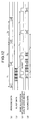
- the band allocation section 13 of the host station apparatus 10 generates values of "GRANT” with the same period as the periodic data and additionally generates values of "GRANT” for the burst data in the burst manner, and the slave station apparatus 20-1 transmits their multiplexed result to the host station apparatus (see Fig. 11).
- the periodicity of the periodic data "a1” through "a4" is maintained.
- time difference between the periodic data to be input into the buffer memory 25a and "GRANT" generated for the periodic data namely time difference between the periodic data and the data reading signal is small
- the periodic data "a1" through “a4" transmitted from the slave station apparatus 20-1 keep the periodicity.
- the optical burst transmission/reception control system comprises a plurality of slave station apparatuses which commonly use a transmission medium and a transmission band, and a host station apparatus posts band allocation information for controlling allocation of use transmission bands of the slave station apparatuses to the slave station apparatuses.
- the respective slave station apparatuses transmit data to the host station apparatus based on the band allocation information posted from the host station apparatus.
- the host station apparatus has a band allocation control unit which generates the band allocation information including identifications of the slave station apparatuses and types of data to be transmitted by the slave station apparatuses and posting the information to the plurality of slave station apparatuses.
- the plurality of slave station apparatuses have a data transmission control which identifies as to whether or not the band allocation information is band allocation information about the data types of their slave station apparatuses, and when the band allocation information is the band allocation information about the data types of their slave station apparatuses, making control so as to transmit data to the host station apparatus according to the data types represented by the band allocation information.
- the band allocation control unit of the host station apparatus generates the band allocation information including identifications of the slave station apparatuses and types of data to be transmitted by the slave station apparatuses, and posts the information to the plural slave station apparatuses, and the data transmission control unit of the plural slave station apparatuses identify as to whether or not the band allocation information is band allocation information for the types of data in their slave station apparatuses, and when the band allocation information is the band allocation information for the types of data in their slave station apparatuses, the data transmission control unit controls itself to transmit data to the host station apparatus according to the types of data represented by the band allocation information.
- the host station apparatus allows the band allocation information to be included in a management information cell so as to post it to the respective slave station apparatuses.
- the band allocation information is use authorizing information of time slots defined in a transmission direction from the slave station apparatuses to the host station apparatus.
- the band allocation information is time slot use authorizing information defined in the transmission direction from the slave station apparatuses to the host station apparatus.
- the data types are types of fixed-speed data which require a real-time property and should be transmitted with constant period and burst data which are generated by transmission request intermittently or temporarily.
- the data types are classified into the fixed-speed dada, which requires the real-time property and should be transmitted with constant period, and the burst data which are generated by transmission request intermittently or temporarily.
- the host station apparatus further has a band change request detection unit which detects intermittent or temporal generation of band change request; and the band allocation control unit, as initial setting, allocates a band to fixed-speed data to be transmitted with constant period, and when the band change request detection unit detects band change request, the band allocation unit allocates a band to burst data which are newly generated intermittently or temporarily.
- the slave station apparatuses further have a band request unit which, when burst data are generated by transmission request intermittently or temporarily, requests the host station apparatus to allocate a band to the burst data.
- the band request unit of the slave station apparatus request the host station apparatus to allocate a band to the burst data.
- the band allocation information is information about grouped plural data types; the band allocation control unit presets information, which represents a band ratio of the grouped plural data types, in the band allocation information; and the data transmission control unit identifies as to whether or not the band allocation information is band allocation information about grouped data types of their slave station apparatuses, and when the band allocation information is the band allocation information about the grouped data types of the slave station apparatuses, transmits data of the grouped plural types represented by the band allocation information according to the band ratio.
- the band allocation information is information about a plurality of data types divided into groups, and the band allocation control unit presets information representing a band ratio between the grouped plural data types in the band allocation information, and the data transmission control unit identifies as to whether or not the band allocation information is band allocation information about the grouped data types of the slave station apparatus.
- the data transmission control unit transmits the data of the grouped plural data types represented by the band allocation information according to the band ratio.
- the band allocation control unit when the band allocation control unit controls band allocation for a slave station apparatus which does not identify a type of data to be transmitted, the band allocation control unit posts band identification information including identification of the slave station apparatus to the slave station apparatus, and when the band allocation control unit controls band allocation for a slave station apparatus which identify a type of data to be transmitted, the band allocation control unit posts band allocation information including the identification of the slave station apparatus and the data type to the slave station apparatus.
- the host station apparatus is used in an optical burst transmission/reception control system.
- This optical burst transmission/reception control system includes a plurality of slave station apparatuses which commonly use a transmission medium and a transmission band, and a host station apparatus posts band allocation information for controlling allocation of use transmission bands of the slave station apparatuses to the slave station apparatuses.
- the respective slave station apparatuses transmit data to the host station apparatus based on the band allocation information posted from the host station apparatus.
- the host device comprises a band allocation control unit which generates the band allocation information including identifications of the slave station apparatuses and types of data to be transmitted by the slave station apparatuses, and posting the information to the plural slave station apparatuses.
- the band allocation control unit generates the band allocation information including identifications of the respective slave station apparatuses and types of data to be transmitted by the slave station apparatuses, and posts them to the plural slave station apparatuses.
- the slave station apparatus comprises a data transmission control unit which identifies as to whether or not the band allocation information is band allocation information about a data type of its slave station apparatus, and when the band allocation information is the band allocation information about the data type of the slave station apparatus, making control so as to transmit data to the host station apparatus.
- the data transmission control unit identifies as to whether or not the band allocation information is band allocation information about data types of their station apparatus, and when the band allocation information is band allocation information about the data type of the station apparatus, the data transmission control unit makes control so as to transmit data to the host station apparatus according to data types represented by the band allocation information.
- the optical burst transmission/reception control method is a method in which a plurality of slave station apparatuses commonly use a transmission medium and a transmission band, and a host station apparatus posts band allocation information for controlling allocation of use transmission bands of the slave station apparatuses to the slave station apparatuses, and the respective slave station apparatuses transmit data to the host station apparatus based on the band allocation information posted from the host station apparatus.
- the optical burst transmission/reception control method comprises the initial post step of previously posting the band allocation information including identifications of the slave station apparatuses and types of data to be transmitted by the slave station apparatuses from the host apparatus to the plurality of slave station apparatuses; the holding step of holding the band allocation information posted at the initial post step by means of the slave station apparatuses; the post step of posting the band allocation information including instruction of bands from the host station apparatus to the slave station apparatuses; and data transmission control step of identifying as to whether or not the band allocation information posted at the post step is band allocation information about data types of the slave station apparatuses respectively by means of the slave'station apparatuses, and when the band allocation information is the band allocation information about the data types of the slave station apparatuses, making control to transmit data to the host station apparatus according to the data types represented by the band allocation information.
- the host station apparatus previously posts the band allocation information including identifications of the slave station apparatuses and types of data to be transmitted by the slave station apparatuses to the plural slave station apparatuses, and at the holding step the slave station apparatuses hold the band allocation information posted at the initial post step, and at the post step the host station apparatus posts the band allocation information including band instruction to the slave station apparatuses, and at the data transmission control step the slave station apparatuses identify as to whether or not the band allocation information posted at the post step is their band allocation information for data types of the slave station apparatuses, and when the band allocation information is band allocation information for the data types of the slave station apparatuses, the slave station apparatuses make control to transmit the data to the host station apparatus according to the data types represented by the band allocation information.
- a band for the burst data is controlled separately from the periodic data.
- the band allocation information posted at the initial post step and at the post step is information about a plurality of grouped data types.
- the band allocation information which are posted by the initial post step and the post step is information about plural grouped data types.
- the above-mentioned optical burst transmission/reception control method further comprises the detection step of detecting as to whether or not burst data are input into the slave station apparatuses by the slave station apparatuses; and the band request step of, when the detection step detects the input of the burst data, transmitting band request of the burst data to the host station apparatus, wherein when the host station apparatus detects the band request, the post step posts the band request including the band allocation information about the burst data to the slave station apparatuses.
- the slave station apparatus detects as to whether or not burst data are input into itself, and when the detection step detects input of burst data, at the band request step band request for the burst data is transmitted to the host station apparatus, and when the host station apparatus detects the band request, at the post step the band allocation information for the burst data is included in the band request so as to be posted to the slave station apparatus.
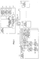
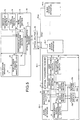
- Fig. 1 is a block diagram showing a structure of the optical burst transmission/reception control system according to the first embodiment of the present invention.
- a service management section 15 is further provided in the optical burst transmission/reception control system shown in Fig. 9, and a service identification section 29 is further provided in the slave station apparatuses 20-1 through 20-n.
- data reading sections 24a and 24b for reading data from buffer memories 25a and 25b are provided instead of the data reading section 24 in the optical burst transmission/reception control system shown in Fig. 9, data reading sections 24a and 24b for reading data from buffer memories 25a and 25b are provided.
- a multiplexing section 28 is provided instead of the multiplexing section 27, and the multiplexing section 28 multiplexes data read by the data reading sections 24a and 24b so as to transmit them to an optical transmitter-receiver 21.
- the other parts of the structure are the same as those in the optical burst transmission/reception control system shown in Fig. 9, and the same reference numerals are given to the same parts of the structure.
- the service management section 15 makes different codes as values of "GRANT" have one to one correspondence to respective types of data input into the slave station apparatuses 20-1 through 20-n, and transmits this correspondence information to a code allocation section 14.
- the types of data are classified into periodic data and burst data.
- the code allocation section 14 shown in Fig. 9 the code allocation section 14 transmits the code values to a management signal transmission section 12, and the management signal transmission section 12 transmits a management signal including this code values to the slave station apparatuses 20-1 through 20-n via an optical transmitter-receiver 11, a main fiber 31, an optical splitter 30, branch fibers 32-1 through 32-n.
- the code identification sections 22 of the slave station apparatuses 20-1 through 20-n fetch identification numbers which are preset in the respective slave station apparatuses and the code values (values of GRANT) having one to one correspondence to the identification numbers and store them.
- the service identification sections 29 post the values of "GRANT" of periodic data to the data reading sections 24a for reading periodic data, and post the values of "GRANT" of burst data to the data reading sections 24b for reading burst data.
- a band allocation section 13 of the host station apparatus 10 inserts the values of "GRANT", which are preset according to the types of data for the respective slave station apparatuses 20-1 through 20-n, into upstream slot allocation areas in a downstream management signal with a frequency according to bands required by various data in the slave station apparatuses 20-1 through 20-n, and transmits them to the management signal transmission section 12.
- the management signal transmission section 12 transmits the management signal to the slave station apparatuses 20-1 through 20-n via the optical transmitter-receiver 11, the main fiber 31, the optical splitter and the branch fibers 32-1 through 32-n.
- Allocation identification section s23 of the slave station apparatuses 20-1 through 20-n detect the values of "GRANT" in the management signal and posts them to the data reading sections 24a and 24b.
- the data reading sections 24a and 24b check the values of the upstream slot allocation areas input from the allocation identification sections 23, and when the values match with the code values (values of GRANT) posted from the service identification sections 29, the data reading sections 24a and 24b try to read data from the buffer memories 25a and 25b respectively with respect to upstream time slots corresponding to the matched slots.
- the data reading sections 24a and 24b transmit the read data to the multiplexing sections 28, and when data do not exist, they generate and transmit empty data to the multiplexing sections 28.
- the multiplexing sections 28 multiplex the input data and transmit them to the optical transmitter-receivers 21, and transmits them to the host station apparatus 10 via the branch fibers 32-1 through 32-n, the optical splitter 30 and the main fiber 31.
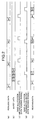
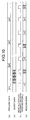
- Fig. 2(a) and 2(b) show the periodic data “a1” through “a4" and the burst data “b1” through “b4".
- Fig. 2(c) shows a periodic data reading signal, which corresponds to band allocation information for the periodic data and represents timing at which the data reading sections 24a read periodic data 26a ("a1” through “a4") from the buffer memories 24a.
- FIG. 2(d) shows a burst data reading signal, which corresponds to band allocation information for the burst data and represents timing at which the data reading sections 24b read burst data 26b ("b1" through "b4") from the buffer memories 25b. Further, Fig. 2(e) shows reading data which are read by the periodic data reading signal and the burst data reading signal and are output from the data reading sections 24a and 24b.
- the band allocation information detected by the allocation identification sections 23 is input with an interval corresponding to bands required for the transmission of the periodic data and burst data, and the periodic data reading signal and the burst data reading signal shown in Figs. 2 (c) and 2 (d) are generated according to the input.
- the data reading sections 24a and 24b read the periodic data "a1” through “a4" and the burst data "b1” through “b4" according to the periodic data reading signal and the burst data reading signal respectively.
- the periodic data "a1” through “a4" are read with an interval of the slots allocated to the periodic data so as to be transmitted to the host station apparatus 10, and thus periodicity of the periodic data is maintained.
- the service management section 15 of the host station apparatus 10 provides values of "GRANT" for respective types of data to the slave station apparatuses 20-1 through 20-n so as to control the bands, and the slave station apparatuses 20-1 through 20-n read data for the respective types of the data. For this reason, for example in the case where periodic data and burst data are transmitted from one slave station, the data can be transmitted to the host station apparatus 10 in a state that the periodicity is maintained without deteriorating the periodicity of the periodic data.
- a second embodiment of the present invention will be explained below.
- all the slave station apparatuses 20-1 through 20-n have the same structure, but in the second embodiment the system is constituted so that the slave station apparatuses 20-1 through 20-n in the first embodiment and the slave station apparatuses 20-1 through 20-n shown in Fig. 9 coexist.
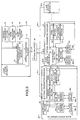
- Fig. 3 is a block diagram showing the structure of the optical burst transmission/reception control system according to the second embodiment of the present invention.
- the slave station apparatuses 20-1 through 20-n the slave station apparatuses having the structure of the slave station apparatuses 20-1 through 20-n in the first embodiment and the slave station apparatuses having the structure of the slave station apparatuses 20-1 through 20-n shown in Fig. 9 coexist as mentioned above.
- the slave station apparatus 20-1 has the same structure as that of the slave station apparatuses 20-1 through 20-n in the first embodiment
- the slave station apparatus 20-n has the same structure as that of the slave station apparatuses 20-1 through 20-n shown in Fig. 9.
- the other parts of the structure are the same as in the first embodiment and the same reference numerals are given to the common parts of the structure.
- the periodicity of the periodic data can be maintained, and the system can be constituted so that the conventional slave station apparatus 20-2 coexists. For this reason, the flexible system can be structured.
- a third embodiment of the present invention will be explained below.
- the system where the slave station apparatuses 20-1 through 20-n in the first embodiment and the conventional slave station apparatuses 20-1 through 20-n shown in Fig. 9 coexist is structured, but in the third embodiment the system is structured so that the internal structure of the slave station apparatuses 20-1 through 20-n in the first embodiment is mixed with the internal structure of the conventional slave station apparatuses 20-1 through 20-n shown in Fig. 9.
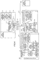
- Fig. 4 is a block diagram showing the structure of the optical burst transmission/reception control system according to the third embodiment of the present invention.
- the slave station apparatus 20-1 is provided with a data reading section 41, two buffer memories 42a and 42b and a multiplexing section 44 instead of the data reading section 24b and the buffer memory 25b in the second embodiment.
- the data reading section 41, the two buffer memories 42a and 42b, and the multiplexing section 44 correspond to the data reading section 24 and the two buffer memories 25a and 25b, and the multiplexing section 27 shown in Fig. 9.
- the slave station apparatuses 20-1 through 20-n may have the same structure of the slave structure 20-1, but in Fig.
- the structure of the slave station apparatus 20-2 is the same as the structure of the slave structure apparatuses 20-1 through 20-n shown in Fig. 9. Namely, the slave station apparatuses 20-1 through 20-n shown in Fig. 9 coexist.
- the other parts of the structure are the same as in the second embodiment, and the same reference numerals are given to the common parts of the structure.
- the service management section 15 of the host station apparatus 10 makes codes values as values of "GRANT" correspond to type groups of data to be input into the slave station apparatus 20-1, and transmits the correspondence information and band ratio of the groups to the code allocation section 14. For example, in the slave station apparatus 20-1, since periodic data are input into the buffer memory 25a and two types of burst data are input into the buffer memories 42a and 42b respectively, the service management section 15 sets the two types of the burst data "1" (43a) and "2" (43b) as one group, and makes one code of a value of "GRANT" correspond to this group. Moreover, the service management section 15 makes one type of periodic data correspond to one code of a value of "GRANT".
- the service management section 15 makes the slave station apparatus 20-1 correspond to two different values of "GRANT". Further, a band ratio is set for the two types of burst data 43a and 43b. Here, the slave station apparatus 20-2 is made to correspond to one value of "GRANT”.
- the information is transmitted to the management signal transmission section 12, and the management signal transmission section 12 inserts the information into a management signal so as to transmit it to the slave station apparatuses 20-1 through 20-n.
- the service identification section 29 of the slave station apparatus 20-1 recognizes the value of "GRANT" set for the periodic data 26a, the values of "GRANT” set for the burst data 43a and 43b and the band ratio, and posts the value of "GRANT” set for the periodic data 26a to the data reading section 24a, and posts the values of "GRANT” set for the burst data 43a and 43b and the band ratio to the data reading section 41.
- the band allocation section 13 of the host station apparatus 10 transmits the values of "GRANT", which are preset for the periodic data 26a and the burst data 43a and 43b in the slave station apparatus 20-1, to the management signal transmission section 12 according to a frequency corresponding to a band required by the periodic data 26a and a frequency corresponding to a total band required by the burst data 43a and 43b in the slave station apparatus 20-1.
- the management signal transmission section 12 inserts the input values of "GRANT" into the upstream slot allocation areas in the management signal so as to transmit them to the slave station apparatus 20-1.
- This management signal is similarly transmitted with a frequency corresponding to a total sum of the bands required by the various data to be input into the slave station apparatuses 20-1 through 20-n.
- the values of "GRANT" which are preset for the slave station apparatuses 20-1 through 20-n are inserted into the upstream slot allocation areas in the management signal.
- the allocation identification section 23 of the slave station apparatus 20-1 detects the values of "GRANT” in the management signal input from the host station apparatus 10, and posts the values of "GRANT” to the data reading sections 24a and 24b.
- the data reading sections 24a and 24b check the values of "GRANT” input from the allocation identification section 23, and when the values match with the codes (values of GRANT) posted from the service identification section 29, the data reading sections 24a and 24b attempt to read the data in the buffer memories 25a and 42a correspondingly to upstream time slots corresponding to the values of "GRANT" which are detected as the matched values.
- the data reading sections 24a and 24b transmit the data to the multiplexing section 28, and when the data to be read do not exist, they generate empty data so as to transmit them to the multiplexing section 28.
- the data reading section 41 controls a reading time ratio of the burst data 43a in the buffer memory 42a to the burst data 43b in the buffer memory 42b based on the band ratio in the group transmitted from the service identification section 29. For example, in the case where the band ratio of the burst data 43a to the burst data 43b is 1:2, the first reading is executed for the buffer memory 42a once and for the buffer memory 42b twice. In the case where data to be read do not exist in one buffer memory, the data reading section 41 attempts to read from the other buffer memory.
- the slave station apparatuses 20-1 through 20-n in the first embodiment are connected as the slave station apparatuses in the fourth embodiment, and the slave station apparatuses in the first embodiment, the slave station apparatuses in the third embodiment and the conventional slave station apparatuses shown in Fig. 9 may coexist.
- the data stored in the plural buffer memories form groups, and one value of "GRANT" is set for each of the groups, and the band ratio of the data in the group is set. For this reason, the band for the respective data in the group can be controlled collectively and flexibility of the structure can be secured.
- the periodicity of the periodic data is not deteriorated.
- the reading control of the periodic data 26a in the slave station apparatuses 20-1 through 20-n is the same as the reading control of the periodic data 26a in the slave station apparatuses 20-1 through 20-n in the first embodiment.
- the periodicity of periodic data can be maintained.
- slave station apparatuses having another structure may be connected as the slave station apparatuses 20-1 through 20-n and they may be coexist.
- the band change request/unrequest monitor 17 may allocate bands based on not only the transmission request from the upstream management signal but also a band change request signal 17 input from an apparatus connected to the host station apparatus 10.
- a band allocation control unit of the host station apparatus generates the band allocation information including identifications of the slave station apparatuses and types of data to be transmitted by the slave station apparatuses, and posts the information to the plural slave station apparatuses, and a data transmission control unit of the plural slave station apparatuses identify as to whether or not the band allocation information is band allocation information for the types of data in their slave station apparatuses, and when the band allocation information is the band allocation information for the types of data in their slave station apparatuses, the data transmission control unit controls itself to transmit data to the host station apparatus according to the types of data represented by the band allocation information.
- the band control for the burst data is made separately from the periodic data. For this reason, the periodicity of the periodic data can be maintained securely, and a delay of transmission of the periodic data can be suppressed minimally.
- the slave station apparatus detects as to whether or not burst data are input into itself, and when the detection step detects input of burst data, at the band request step band request for the burst data is transmitted to the host station apparatus, and when the host station apparatus detects the band request, at the post step the band allocation information for the burst data is included in the band request so as to be posted to the slave station apparatus. For this reason, only when transmission of the burst data is required, the burst data can be transmitted, and transmission bands can be used efficiently.
Landscapes
- Engineering & Computer Science (AREA)
- Computer Networks & Wireless Communication (AREA)
- Signal Processing (AREA)
- Small-Scale Networks (AREA)
- Optical Communication System (AREA)
- Time-Division Multiplex Systems (AREA)
Abstract
Description
Claims (13)
- An optical burst transmission/reception control system comprising:wherein said host station apparatus has a band allocation control unit which generates the band allocation information including identifications of said slave station apparatuses and types of data to be transmitted by said slave station apparatuses and posting the information to said plurality of slave station apparatuses, anda plurality of slave station apparatuses which commonly use a transmission medium and a transmission band, anda host station apparatus which posts band allocation information for controlling allocation of use transmission bands of said slave station apparatuses to said slave station apparatuses, wherein said respective slave station apparatuses transmit data to said host station apparatus based on the band allocation information posted from said host station apparatus,
wherein said plurality of slave station apparatuses have a data transmission control unit which identifies as to whether or not the band allocation information is band allocation information about the data types of their slave station apparatuses, and when the .band allocation information is the band allocation information about the data types of their slave station apparatuses, making control so as to transmit data to said host station apparatus according to the data types represented by the band allocation information. - The optical burst transmission/reception control system according to claim 1, wherein said host station apparatus allows the band allocation information to be included in a management information cell so as to post it to said respective slave station apparatuses.
- The optical burst transmission/reception control system according to claim 1, wherein the band allocation information is use authorizing information of time slots defined in a transmission direction from said slave station apparatuses to said host station apparatus.
- The optical burst transmission/reception control system according to claim 1, wherein the data types are types of fixed-speed data which require a real-time property and should be transmitted with constant period and burst data which are generated by transmission request intermittently or temporarily.
- The optical burst transmission/reception control system according to claim 1,
wherein said host station apparatus further has a band request detection unit which detects intermittent or temporal generation of band request, and
wherein said band allocation control unit, as initial setting, allocates a band to fixed-speed data to be transmitted with constant period, and when said band request detection unit detects band request, said a band allocation unit allocates a band to burst data which are newly generated intermittently or temporarily. - The optical burst transmission/reception control system according to claim 1, wherein said slave station apparatuses further have a band request unit which, when burst data are generated by transmission request intermittently or temporarily, requests said host station apparatus to allocate a band to the burst data.
- The optical burst transmission/reception control system according to claim 1,
wherein the band allocation information is information about grouped plural data types,
wherein said band allocation control unit presets information, which represents a band ratio of the grouped plural data types, in the band allocation information, and
wherein said data transmission control unit identifies as to whether or not the band allocation information is band allocation information about grouped data types of their slave station apparatuses, and when the band allocation information is the band allocation information about the grouped data types of the slave station apparatuses, transmits data of the grouped plural types represented by the band allocation information according to the band ratio. - The optical burst transmission/reception control system according to claim 1, wherein when the band allocation control unit controls band allocation for a slave station apparatus which does not identify a type of data to be transmitted, said band allocation control unit posts band identification information including identification of the slave station apparatus to the slave station apparatus, and when the band allocation control unit controls band allocation for a slave station apparatus which identify a type of data to be transmitted said band allocation control unit posts band allocation information including the identification of the slave station apparatus and the data type to the slave station apparatus.
- A host station apparatus used in an optical burst transmission/reception control system that includes
a plurality of slave station apparatuses which commonly use a transmission medium and a transmission band, and
a host station apparatus which posts band allocation information for controlling allocation of use transmission bands of said slave station apparatuses to said slave station apparatuses, wherein said respective slave station apparatuses transmit data to said host station apparatus based on the band allocation information posted from said host station apparatus,
said host station apparatus comprises a band allocation control unit which generates the band allocation information including identifications of said slave station apparatuses and types of data to be transmitted by said slave station apparatuses, and posting the information to said plural slave station apparatuses. - A slave station apparatus used in an optical burst transmission/reception control system that includes
a plurality of slave station apparatuses which commonly use a transmission medium and a transmission band, and
a host station apparatus which posts band allocation information for controlling allocation of use transmission bands of said slave station apparatuses to said slave station apparatuses, wherein said respective slave station apparatuses transmit data to said host station apparatus based on the band allocation information posted from said host station apparatus,
said slave station apparatus comprises a data transmission control unit which identifies as to whether or not the band allocation information is band allocation information about a data type of its slave station apparatus, and when the band allocation information is the band allocation information about the data type of the slave station apparatus, making control so as to transmit data to said host station apparatus. - An optical burst transmission/reception control method, in which a plurality of slave station apparatuses commonly use a transmission medium and a transmission band, and a host station apparatus posts band allocation information for controlling allocation of use transmission bands of said slave station apparatuses to said slave station apparatuses, and said respective slave station apparatuses transmit data to said host station apparatus based on the band allocation information posted from the host station apparatus, the method comprising:the initial post step of previously posting the band allocation information including identifications of said slave station apparatuses and types of data to be transmitted by said slave station apparatuses from said host apparatus to said plurality of slave station apparatuses;the holding step of holding the band allocation information posted at the initial post step by means of said slave station apparatuses;the post step of posting the band allocation information including instruction of bands from said host station apparatus to said slave station apparatuses; andthe data transmission control step of identifying as to whether or not the band allocation information posted at the post step is band allocation information about data types of said slave station apparatuses respectively by means of said slave station apparatuses, and when the band allocation information is the band allocation information about the data types of said slave station apparatuses, making control to transmit data to said host station apparatus according to the data types represented by the band allocation information.
- The optical burst transmission/reception control method according to claim 11, wherein the band allocation information posted at the initial post step and at the post step is information about a plurality of grouped data types.
- The optical burst transmission/reception control method according to claim 11, further comprising:wherein when said host station apparatus detects the band request, said post step posts the band request including the band allocation information about the burst data to said slave station apparatuses.the detection step of detecting as to whether or not burst data are input into said slave station apparatuses by said slave station apparatuses, andthe band request step of, when the detection step detects the input of the burst data, transmitting band request of the burst data to said host station apparatus,
Priority Applications (1)
| Application Number | Priority Date | Filing Date | Title |
|---|---|---|---|
| EP10002873.7A EP2192723B1 (en) | 2000-06-19 | 2001-06-08 | Optical burst transmission/reception control system, slave station apparatus to be used therein and optical burst transmission/reception control method |
Applications Claiming Priority (3)
| Application Number | Priority Date | Filing Date | Title |
|---|---|---|---|
| JP2000183686 | 2000-06-19 | ||
| JP2000183686A JP3643016B2 (en) | 2000-06-19 | 2000-06-19 | Optical burst transmission / reception control system, master station apparatus, slave station apparatus and optical burst transmission / reception control method used therefor |
| PCT/JP2001/004847 WO2001099351A1 (en) | 2000-06-19 | 2001-06-08 | Light burst transmission/reception control system, parent station device used in the same, child station device, and light burst transmission/reception control method |
Related Child Applications (2)
| Application Number | Title | Priority Date | Filing Date |
|---|---|---|---|
| EP10002873.7A Division EP2192723B1 (en) | 2000-06-19 | 2001-06-08 | Optical burst transmission/reception control system, slave station apparatus to be used therein and optical burst transmission/reception control method |
| EP10002873.7A Division-Into EP2192723B1 (en) | 2000-06-19 | 2001-06-08 | Optical burst transmission/reception control system, slave station apparatus to be used therein and optical burst transmission/reception control method |
Publications (3)
| Publication Number | Publication Date |
|---|---|
| EP1206078A1 true EP1206078A1 (en) | 2002-05-15 |
| EP1206078A4 EP1206078A4 (en) | 2009-07-22 |
| EP1206078B1 EP1206078B1 (en) | 2014-08-13 |
Family
ID=18684231
Family Applications (2)
| Application Number | Title | Priority Date | Filing Date |
|---|---|---|---|
| EP01936916.4A Expired - Lifetime EP1206078B1 (en) | 2000-06-19 | 2001-06-08 | Host station device used in an optical burst transmission/reception control system including slave station devices |
| EP10002873.7A Expired - Lifetime EP2192723B1 (en) | 2000-06-19 | 2001-06-08 | Optical burst transmission/reception control system, slave station apparatus to be used therein and optical burst transmission/reception control method |
Family Applications After (1)
| Application Number | Title | Priority Date | Filing Date |
|---|---|---|---|
| EP10002873.7A Expired - Lifetime EP2192723B1 (en) | 2000-06-19 | 2001-06-08 | Optical burst transmission/reception control system, slave station apparatus to be used therein and optical burst transmission/reception control method |
Country Status (4)
| Country | Link |
|---|---|
| US (1) | US7139487B2 (en) |
| EP (2) | EP1206078B1 (en) |
| JP (1) | JP3643016B2 (en) |
| WO (1) | WO2001099351A1 (en) |
Families Citing this family (12)
| Publication number | Priority date | Publication date | Assignee | Title |
|---|---|---|---|---|
| ATE354229T1 (en) * | 2002-05-21 | 2007-03-15 | Cit Alcatel | POINT-TO-MULTI-POINT TELECOMMUNICATION SYSTEM WITH DOWNWARD FRAME STRUCTURE |
| US7688843B2 (en) * | 2002-09-13 | 2010-03-30 | Pmc-Sierra Israel Ltd. | Operations method in an ethernet passive optical network that includes a network unit with multiple entities |
| JP2004186932A (en) * | 2002-12-03 | 2004-07-02 | Fujitsu Ltd | Optical access system |
| DE10339039A1 (en) * | 2003-08-25 | 2005-04-07 | Siemens Ag | Method for transmitting data packets |
| US7328026B2 (en) * | 2004-08-11 | 2008-02-05 | Mitsubishi Electric Research Laboratories, Inc. | Signaling in a wireless network with sequential coordinated channel access |
| US7697547B2 (en) * | 2004-12-08 | 2010-04-13 | Alcatel Lucent | Internet protocol video delivery in passive optical networks |
| JP4414382B2 (en) * | 2005-08-16 | 2010-02-10 | 東京エレクトロンデバイス株式会社 | OPTICAL NETWORK SYSTEM, OPTICAL NETWORK DEVICE, AND OPTICAL NETWORK CONTROL METHOD |
| US8180223B2 (en) * | 2006-02-03 | 2012-05-15 | Fujitsu Limited | System and method for extending reach in a passive optical network |
| US20070280690A1 (en) * | 2006-06-02 | 2007-12-06 | Fujitsu Limited | System and Method for Managing Power in an Optical Network |
| US7970281B2 (en) * | 2007-01-26 | 2011-06-28 | Fujitsu Limited | System and method for managing different transmission architectures in a passive optical network |
| US8588245B2 (en) * | 2009-02-17 | 2013-11-19 | Telefonaktiebolaget L M Ericsson (Publ) | Methods and systems for frame generation in communication networks |
| WO2018003117A1 (en) * | 2016-07-01 | 2018-01-04 | 三菱電機株式会社 | Communication system and communication method |
Family Cites Families (11)
| Publication number | Priority date | Publication date | Assignee | Title |
|---|---|---|---|---|
| JP2730338B2 (en) | 1991-07-15 | 1998-03-25 | 日本電気株式会社 | Satellite communication system |
| AU704526B2 (en) * | 1995-03-24 | 1999-04-29 | British Telecommunications Public Limited Company | Optical network |
| US5953344A (en) * | 1996-04-30 | 1999-09-14 | Lucent Technologies Inc. | Method and apparatus enabling enhanced throughput efficiency by use of dynamically adjustable mini-slots in access protocols for shared transmission media |
| JPH10336187A (en) | 1997-05-28 | 1998-12-18 | Nippon Telegr & Teleph Corp <Ntt> | Band allocation circuit |
| JPH1117685A (en) | 1997-06-20 | 1999-01-22 | Oki Electric Ind Co Ltd | Band management circuit, transmitter and transmission system |
| JP3064978B2 (en) | 1997-07-25 | 2000-07-12 | 日本電気株式会社 | Polling method and method |
| JPH1146198A (en) | 1997-07-25 | 1999-02-16 | Nec Corp | Polling method and system |
| US6393007B1 (en) * | 1997-10-16 | 2002-05-21 | Telefonaktiebolaget Lm Ericsson (Publ) | Method of and a system for voice and data radio communication providing improved interference diversity |
| WO1999038292A1 (en) * | 1998-01-23 | 1999-07-29 | Kabushiki Kaisha Toshiba | Point-to-multipoint communication system |
| JP3055534B2 (en) * | 1998-07-21 | 2000-06-26 | 日本電気株式会社 | Optical subscriber system |
| US6909719B1 (en) * | 1999-12-22 | 2005-06-21 | Ericsson Inc. | Method, apparatus and system for providing multiple quality of service classes to subscribers in a network |
-
2000
- 2000-06-19 JP JP2000183686A patent/JP3643016B2/en not_active Expired - Fee Related
-
2001
- 2001-06-08 US US10/049,855 patent/US7139487B2/en not_active Expired - Lifetime
- 2001-06-08 EP EP01936916.4A patent/EP1206078B1/en not_active Expired - Lifetime
- 2001-06-08 WO PCT/JP2001/004847 patent/WO2001099351A1/en not_active Ceased
- 2001-06-08 EP EP10002873.7A patent/EP2192723B1/en not_active Expired - Lifetime
Also Published As
| Publication number | Publication date |
|---|---|
| US20020114043A1 (en) | 2002-08-22 |
| EP2192723A2 (en) | 2010-06-02 |
| US7139487B2 (en) | 2006-11-21 |
| EP1206078A4 (en) | 2009-07-22 |
| EP2192723A3 (en) | 2010-06-16 |
| JP2002009804A (en) | 2002-01-11 |
| EP2192723B1 (en) | 2014-07-30 |
| EP1206078B1 (en) | 2014-08-13 |
| JP3643016B2 (en) | 2005-04-27 |
| WO2001099351A1 (en) | 2001-12-27 |
Similar Documents
| Publication | Publication Date | Title |
|---|---|---|
| KR100251692B1 (en) | Fiber optic subscriber network | |
| JP6841919B2 (en) | Data communication system, optical network unit, and baseband device | |
| AU2314201A (en) | Method and apparatus for TDM/TDMA communications | |
| EP2109256A1 (en) | Pon group broadcast communication system, group broadcast managing method and the corresponding device | |
| US7139487B2 (en) | Light burst transmission/reception control system, parent station device used in the same, child station device, and light burst transmission/reception control method | |
| US7512337B2 (en) | Gigabit ethernet passive optical network having double link structure | |
| US20020021471A1 (en) | Unused band use right acquisition controlling method and passive optical network for the same | |
| US20090034964A1 (en) | Communication apparatus communicating with different bit rates | |
| EP0504248B1 (en) | Optical fibre communications system | |
| JP3715423B2 (en) | COMMUNICATION SYSTEM AND USER DEVICE AND CENTER DEVICE USED IN THE COMMUNICATION SYSTEM | |
| US20090175622A1 (en) | Method for allocating upstream transmission bandwidth in wdm-epon | |
| US6888846B2 (en) | Data transfer in an optical network communication system | |
| KR20020011026A (en) | Method of grant request for mac protocol in pon | |
| KR100566294B1 (en) | Dynamic Bandwidth Allocation Method for Gigabit Ethernet Passive Optical Subscriber Network | |
| US20090148165A1 (en) | Optical filtering apparatus and optical communication system | |
| KR100646386B1 (en) | Dynamic Bandwidth Allocation Method in Wavelength Division Multiplexing Passive Optical Subscriber Network with Loopback Scheme | |
| JP4719352B2 (en) | Method for dividing upstream time slots in a time division multiple access system, associated line terminator, and associated network terminator | |
| KR100704111B1 (en) | Data processing device and method for transmission convergence layer function in passive optical branch network | |
| KR100493071B1 (en) | Method for controlling bandwidth in ethernet passive optical network | |
| JP4011387B2 (en) | Delay measurement control method and apparatus for optical burst transmission / reception network | |
| KR20030040934A (en) | MAC scheduling apparatus and method of OLT in PON | |
| JP2002344470A (en) | Optical burst transmission / reception control system | |
| JP2005341614A (en) | COMMUNICATION SYSTEM AND USER DEVICE AND CENTER DEVICE USED IN THE COMMUNICATION SYSTEM | |
| JP2000101621A (en) | Access control method | |
| HK111797A (en) | Optical fibre communications system |
Legal Events
| Date | Code | Title | Description |
|---|---|---|---|
| PUAI | Public reference made under article 153(3) epc to a published international application that has entered the european phase |
Free format text: ORIGINAL CODE: 0009012 |
|
| 17P | Request for examination filed |
Effective date: 20020218 |
|
| AK | Designated contracting states |
Kind code of ref document: A1 Designated state(s): AT BE CH CY DE DK ES FI FR GB GR IE IT LI LU MC NL PT SE TR |
|
| RBV | Designated contracting states (corrected) |
Designated state(s): DE FR GB |
|
| RAP1 | Party data changed (applicant data changed or rights of an application transferred) |
Owner name: MITSUBISHI DENKI KABUSHIKI KAISHA |
|
| A4 | Supplementary search report drawn up and despatched |
Effective date: 20090622 |
|
| 17Q | First examination report despatched |
Effective date: 20090903 |
|
| REG | Reference to a national code |
Ref country code: DE Ref legal event code: R079 Ref document number: 60148955 Country of ref document: DE Free format text: PREVIOUS MAIN CLASS: H04L0012440000 Ipc: H04L0012540000 |
|
| GRAP | Despatch of communication of intention to grant a patent |
Free format text: ORIGINAL CODE: EPIDOSNIGR1 |
|
| RIC1 | Information provided on ipc code assigned before grant |
Ipc: H04L 12/70 20130101ALI20140114BHEP Ipc: H04L 12/54 20130101AFI20140114BHEP |
|
| INTG | Intention to grant announced |
Effective date: 20140218 |
|
| GRAS | Grant fee paid |
Free format text: ORIGINAL CODE: EPIDOSNIGR3 |
|
| GRAA | (expected) grant |
Free format text: ORIGINAL CODE: 0009210 |
|
| AK | Designated contracting states |
Kind code of ref document: B1 Designated state(s): DE FR GB |
|
| REG | Reference to a national code |
Ref country code: GB Ref legal event code: FG4D |
|
| REG | Reference to a national code |
Ref country code: DE Ref legal event code: R096 Ref document number: 60148955 Country of ref document: DE Effective date: 20140918 |
|
| REG | Reference to a national code |
Ref country code: DE Ref legal event code: R097 Ref document number: 60148955 Country of ref document: DE |
|
| PLBE | No opposition filed within time limit |
Free format text: ORIGINAL CODE: 0009261 |
|
| STAA | Information on the status of an ep patent application or granted ep patent |
Free format text: STATUS: NO OPPOSITION FILED WITHIN TIME LIMIT |
|
| 26N | No opposition filed |
Effective date: 20150515 |
|
| REG | Reference to a national code |
Ref country code: FR Ref legal event code: PLFP Year of fee payment: 16 |
|
| REG | Reference to a national code |
Ref country code: DE Ref legal event code: R084 Ref document number: 60148955 Country of ref document: DE |
|
| REG | Reference to a national code |
Ref country code: FR Ref legal event code: PLFP Year of fee payment: 17 |
|
| REG | Reference to a national code |
Ref country code: GB Ref legal event code: 746 Effective date: 20170424 |
|
| REG | Reference to a national code |
Ref country code: FR Ref legal event code: PLFP Year of fee payment: 18 |
|
| PGFP | Annual fee paid to national office [announced via postgrant information from national office to epo] |
Ref country code: FR Payment date: 20200512 Year of fee payment: 20 Ref country code: DE Payment date: 20200527 Year of fee payment: 20 |
|
| PGFP | Annual fee paid to national office [announced via postgrant information from national office to epo] |
Ref country code: GB Payment date: 20200527 Year of fee payment: 20 |
|
| REG | Reference to a national code |
Ref country code: DE Ref legal event code: R071 Ref document number: 60148955 Country of ref document: DE |
|
| REG | Reference to a national code |
Ref country code: GB Ref legal event code: PE20 Expiry date: 20210607 |
|
| PG25 | Lapsed in a contracting state [announced via postgrant information from national office to epo] |
Ref country code: GB Free format text: LAPSE BECAUSE OF EXPIRATION OF PROTECTION Effective date: 20210607 |