EP1205990A2 - Method for producing electrodes for battery - Google Patents
Method for producing electrodes for battery Download PDFInfo
- Publication number
- EP1205990A2 EP1205990A2 EP01126626A EP01126626A EP1205990A2 EP 1205990 A2 EP1205990 A2 EP 1205990A2 EP 01126626 A EP01126626 A EP 01126626A EP 01126626 A EP01126626 A EP 01126626A EP 1205990 A2 EP1205990 A2 EP 1205990A2
- Authority
- EP
- European Patent Office
- Prior art keywords
- current collector
- active material
- thickness
- coating
- producing electrodes
- Prior art date
- Legal status (The legal status is an assumption and is not a legal conclusion. Google has not performed a legal analysis and makes no representation as to the accuracy of the status listed.)
- Withdrawn
Links
Images


Classifications
-
- H—ELECTRICITY
- H01—ELECTRIC ELEMENTS
- H01M—PROCESSES OR MEANS, e.g. BATTERIES, FOR THE DIRECT CONVERSION OF CHEMICAL ENERGY INTO ELECTRICAL ENERGY
- H01M10/00—Secondary cells; Manufacture thereof
- H01M10/24—Alkaline accumulators
- H01M10/30—Nickel accumulators
-
- H—ELECTRICITY
- H01—ELECTRIC ELEMENTS
- H01M—PROCESSES OR MEANS, e.g. BATTERIES, FOR THE DIRECT CONVERSION OF CHEMICAL ENERGY INTO ELECTRICAL ENERGY
- H01M4/00—Electrodes
- H01M4/02—Electrodes composed of, or comprising, active material
- H01M4/04—Processes of manufacture in general
- H01M4/0402—Methods of deposition of the material
- H01M4/0411—Methods of deposition of the material by extrusion
-
- H—ELECTRICITY
- H01—ELECTRIC ELEMENTS
- H01M—PROCESSES OR MEANS, e.g. BATTERIES, FOR THE DIRECT CONVERSION OF CHEMICAL ENERGY INTO ELECTRICAL ENERGY
- H01M4/00—Electrodes
- H01M4/02—Electrodes composed of, or comprising, active material
-
- H—ELECTRICITY
- H01—ELECTRIC ELEMENTS
- H01M—PROCESSES OR MEANS, e.g. BATTERIES, FOR THE DIRECT CONVERSION OF CHEMICAL ENERGY INTO ELECTRICAL ENERGY
- H01M4/00—Electrodes
- H01M4/02—Electrodes composed of, or comprising, active material
- H01M4/04—Processes of manufacture in general
-
- H—ELECTRICITY
- H01—ELECTRIC ELEMENTS
- H01M—PROCESSES OR MEANS, e.g. BATTERIES, FOR THE DIRECT CONVERSION OF CHEMICAL ENERGY INTO ELECTRICAL ENERGY
- H01M4/00—Electrodes
- H01M4/02—Electrodes composed of, or comprising, active material
- H01M4/04—Processes of manufacture in general
- H01M4/0402—Methods of deposition of the material
- H01M4/0404—Methods of deposition of the material by coating on electrode collectors
-
- H—ELECTRICITY
- H01—ELECTRIC ELEMENTS
- H01M—PROCESSES OR MEANS, e.g. BATTERIES, FOR THE DIRECT CONVERSION OF CHEMICAL ENERGY INTO ELECTRICAL ENERGY
- H01M4/00—Electrodes
- H01M4/02—Electrodes composed of, or comprising, active material
- H01M4/04—Processes of manufacture in general
- H01M4/043—Processes of manufacture in general involving compressing or compaction
-
- H—ELECTRICITY
- H01—ELECTRIC ELEMENTS
- H01M—PROCESSES OR MEANS, e.g. BATTERIES, FOR THE DIRECT CONVERSION OF CHEMICAL ENERGY INTO ELECTRICAL ENERGY
- H01M4/00—Electrodes
- H01M4/02—Electrodes composed of, or comprising, active material
- H01M4/24—Electrodes for alkaline accumulators
- H01M4/26—Processes of manufacture
-
- H—ELECTRICITY
- H01—ELECTRIC ELEMENTS
- H01M—PROCESSES OR MEANS, e.g. BATTERIES, FOR THE DIRECT CONVERSION OF CHEMICAL ENERGY INTO ELECTRICAL ENERGY
- H01M4/00—Electrodes
- H01M4/02—Electrodes composed of, or comprising, active material
- H01M4/64—Carriers or collectors
- H01M4/70—Carriers or collectors characterised by shape or form
- H01M4/72—Grids
- H01M4/74—Meshes or woven material; Expanded metal
- H01M4/745—Expanded metal
-
- Y—GENERAL TAGGING OF NEW TECHNOLOGICAL DEVELOPMENTS; GENERAL TAGGING OF CROSS-SECTIONAL TECHNOLOGIES SPANNING OVER SEVERAL SECTIONS OF THE IPC; TECHNICAL SUBJECTS COVERED BY FORMER USPC CROSS-REFERENCE ART COLLECTIONS [XRACs] AND DIGESTS
- Y02—TECHNOLOGIES OR APPLICATIONS FOR MITIGATION OR ADAPTATION AGAINST CLIMATE CHANGE
- Y02E—REDUCTION OF GREENHOUSE GAS [GHG] EMISSIONS, RELATED TO ENERGY GENERATION, TRANSMISSION OR DISTRIBUTION
- Y02E60/00—Enabling technologies; Technologies with a potential or indirect contribution to GHG emissions mitigation
- Y02E60/10—Energy storage using batteries
Definitions
- This invention relates to a method of producing electrodes for use in batteries such as nickel-hydrogen battery.
- a positive electrode is produced by filling a nickel foam metal, which is a current collector consisting of porous metal having three dimensional pores in communication with each other, with a coating consisting mainly of a nickel hydroxide powder, a binder and a solvent, drying the coating filled current collector, and pressure compressing the same.
- the methods of filling a porous metal with a coating include, for example, the one disclosed in Japanese Patent Publication No. 7-73049.
- a negative electrode is produced by coating both sides of a current collector, which consists of a rolled nickel punching metal containing nickel about 60 ⁇ m thick, with a coating consisting mainly of a hydrogen absorbing alloy, a binder and a solvent, drying the coated current collector, and pressure compressing the same.
- a current collector which consists of a rolled nickel punching metal containing nickel about 60 ⁇ m thick
- a coating consisting mainly of a hydrogen absorbing alloy, a binder and a solvent
- an object of this invention is to provide a method of producing electrodes for batteries in which a current collector of thin foil is coated with an active material coating and the active material coat is formed in such a manner as to ensure high productivity and which enables the improvement in capacity of batteries.
- the 1st invention of the present invention is a method of producing electrodes for a battery, characterized by comprising the steps of:
- the 2nd invention of the present invention is the method of producing electrodes for a battery according to 1st invention, characterized in that the thickness of said metal foil is in a range of 5 to 50 ⁇ m.
- the 3rd invention of the present invention is the method of producing electrodes for a battery according to 1st invention, characterized in that the thickness of the current collector having been subjected to three dimensional processing falls in the range shown by the equation t1 ⁇ t2 ⁇ t1/4, when t1 is the thickness of a electrode plate and t2 is the thickness of the current collector having been subjected to three dimensional processing.
- the 4th invention of the present invention is the method of producing electrodes for a battery according to 1st invention, characterized in that the thickness of the current collector having been subjected to three dimensional processing falls in the range shown by the equation d > t2 ⁇ d/4, when d is the gap between the tips of the pair of dies and t2 is the thickness of the current collector having been subjected to three dimensional processing.
- the 5th invention of the present invention is the method of producing electrodes for a battery according to 1st invention, characterized in that said metal foil is electrolytic nickel foil.
- the 6th invention of the present invention is a method of producing electrodes for a battery in which an active material coating for nickel-hydrogen battery is applied on a current collector using dies so as to form an active material layer, characterized in that the active material coating flows inside the dies as well as between the tip of each die and the current collector at a shear rate of 500 (1/sec) or less.
- the 7th invention of the present invention is the method of producing electrodes for a battery according to 1st or 6th inventions, characterized in that the pressure of the active material coating between the tip of each die and the current collector is 0.5 MPa or lower.
- the 8th invention of the present invention is the method of producing electrodes for a battery according to 1st or 6th inventions, characterized in that the difference in thickness between the active material layer of the front and that of the back of the current collector is within the limits of ⁇ 30%.
- the 9th invention of the present invention is the method of producing electrodes for a battery according to 1st or 6th inventions, characterized in that the difference in thickness between the active material layer of the front and that of the back of the current collector is within the limits of ⁇ 10%.
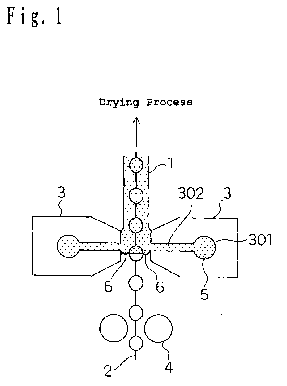
- Fig. 1 is a schematic view of a coater according to this embodiment which is applicable to a method of producing electrodes for batteries of this invention.
- a current collector 2 is formed by processing the front and back of electrolytic nickel foil 203 t0 (5 to 50 ⁇ m) thick so as to have rectangular curbed portions 201 and 202 with prescribed dimensions which are projecting convexly and arranged parallel to each other in the direction X, as shown in Fig. 3.
- embossing using a die can be used. This three dimensional processing allows the current collector 2 to have a larger thickness than the foil does.
- the thickness of the current collector 2 shall be designated by t2 as described later.
- the process of applying a coating on the current collector 2 is carried out while passing the current collector 2 through almost middle portion of a gap formed between a pair of dies 3, as shown in Figs. 1 and 2.
- a certain amount of active material coating 5 (hereinafter referred to as coating for short) is supplied with a pump (not shown in the figure).
- the coating 5 is first supplied to the inside of manifolds 301 where its pressure is uniformed in the transverse direction of the dies 3 coating, allowed to flow in slits 302, extruded from the tips of the dies 3, and applied on both sides of the current collector 2 in the transverse direction simultaneously and uniformly.
- the thickness of the coating applied falls in the range shown by the equation t1 ⁇ t2 ⁇ t1/4, when t1 is the thickness of the electrode plate having been coated with an active material andt2 is the thickness of the current collector having been subjected to three dimensional processing. These are the conditions under which current flows sufficiently.
- Position regulating instruments 4 for current collector which introduce the current collector 2 into almost middle portion of the gap may be provided on the upstream side relative to the dies 3 and, if necessary, on the downstream side relative to the same.
- the position regulating instrument 4 consists of a roll and a bar.
- the current collector having had a coating 5 applied and an active material layer 1 formed thereon is dried in the drying process not shown in the figure, and then taken up. After that, the current collector is subjected to pressure compressing processing in the press working process not shown in the figure so as to be made into an electrode plate.
- a first feature of this embodiment is that the current collector 2 having been subjected to three dimensional processing runs in the middle of the gap formed by the tips of the two dies since it is passed between the tips of the two dies. As a result, a variation in the amount of the coating of the active material layers 1 on the front and back of the current collector 2 becomes very small, whereby the flatness of the electrode plate after the press working becomes excellent.
- the gap g between the tip of each convex portion of the current collector 2 and the tip 304 of each die becomes small.
- d is generally 0.05 mm or more and 3 mm or less.
- the gap g between the tip of each convex portion of the current collector 2 and the tip 304 of each die becomes as very small as 0.1 mm. Accordingly, the forces of viscosity the coating 5 existing in the gap g has inhibit the position of the current collector 2 from being unstable and thereby the current collector 2 is allowed to run in the middle of the gap d between the two dies.
- the tip 304 of each die and the current collector 2 never come in contact with each other; accordingly, even a current collector of which foil thickness is as thin as 5 to 50 ⁇ m and therefore mechanical strength is low can be produced stably without causing cut off thereof.
- a second feature of this embodiment is that the thickness of the current collector falls in the range shown by the equation t1 ⁇ t2 ⁇ t1/4, when t1 is the thickness of the electrode plate and t2 is the thickness of the current collector having been subjected to three dimensional processing. If an active material is coated so thick that the thickness of the current collector does not fall in the above range, a problem arises that electric current is hard to flow.
- a third feature of this embodiment is to use electrolytic nickel foil.
- Foils used as a current collector can be divided into two major categories: rolled nickel foil and electrolytic nickel foil.
- rolled nickel foil At the time of using electrolytic nickel foil, a deformation can be inhibited from being caused in the foil by heating during the drying process for the active material layer, compared with when using rolled nickel foil.
- the rolled nickel foil has a stressing strain caused during the rolling process, and the stressing strain in turn gives rise to warps in the foil when the foil is heated.
- the use of the electrolytic nickel foil results in improvement in accuracy of electrode plate flatness, which in turn makes it easier to wind up positive and negative electrodes and separator, leading to marked improvement in quality and yield of batteries.
- the thickness of the current collector is more than 50 ⁇ m, it is difficult to increase the capacity of batteries, but on the other hand, if the thickness of the current collector is less than 5 ⁇ m, such a problem arises that the current collector cannot with stand the tension required for its running during the coating process, etc . and it is cut off. Accordingly, in this invention, preferably the thickness of the current collector is in the range of 5 to 50 ⁇ m. From the above viewpoint, more preferably the thickness of the current collector is in the range of 10 to 30 ⁇ m.
- a fourth feature of this embodiment is that shear rate for the active material coating which flows inside of dies as well as between the tip of each die and the current collector is 500 (1/sec) or lower.
- the term "shear rate” herein used is defined as V/g, wherein g is the gap between the tip of each die and the current collector and V is the running speed of the current collector.
- Fig. 5 shows viscosity characteristic of the coating used in this embodiment. Measurements were made using Reometer RF-2 manufactured by Reometrix Co., Ltd. equipped with a cone plate type measuring head.
- Fig. 5 measuring time (sec) is plotted in abscissa and viscosity (Pa ⁇ s) in ordinate. The changes of viscosity were measured while changing the shear rate at intervals of 30 seconds; 1 (1/sec), 10 (1/sec), 100 (1/sec) and 1000 (1/sec). Fig. 5 shows the results of two measurements.
- the inventors After conducting an intensive investigation, the inventors have found that this phenomenon is observed in the coating system containing: powders with higher specific gravities, such as powders of nickel hydroxide and hydrogen absorbing alloys, as a main component; a binder, such as CMC and SBR, as small an amount as 3% or less; and 50% or more of solid content, that is, in the coating system for the nickel-hydrogen battery.
- powders with higher specific gravities such as powders of nickel hydroxide and hydrogen absorbing alloys, as a main component
- a binder such as CMC and SBR, as small an amount as 3% or less
- 50% or more of solid content that is, in the coating system for the nickel-hydrogen battery.
- a fifth feature of this invention is that the pressure at the gaps is preferably kept proper. After the intensive investigation, the inventors have found that the pressure at the gaps is closely related to the phenomenon of unstable viscosity. When the pressure at the gaps is 0.5 MPa or less, more preferably 0.3 MPa or less, the phenomenon of unstable viscosity does not occur. This phenomenon may be attributed to the separation of powders and solvent caused by a high pressure at the gaps.
- viscosity ⁇ 1 at a shear rate of 1 (1/sec) is in the range of 1 to 100 (Pa ⁇ s) and viscosity ⁇ 2 at a shear rate of 100 (1/sec) is in the range of 1 (Pa ⁇ s) or less.
- the viscosity ⁇ 1 less than 1 (Pa ⁇ s) permits the coat right after the coating to flow before it is dried, resulting in ununiform thickness of the active material layer.
- the viscosity ⁇ 1 more than 100 (Pa ⁇ s) is not preferable, either, because it does not permit the coat to flow well, and moreover, it permits the phenomenon of instable viscosity to be remarkable at a shear rate of 1000 (1/sec), as described above. If the viscosity ⁇ 2 at a shear rate of 100 (1/sec) is more than 1 (Pa ⁇ s), the pressure of the coating at the gaps between the current collector and the dies becomes higher than 0.5 MPa during the coating process with the dies, which means that coating with the dies becomes impossible.
- this embodiment provides such accurate electrode plates that the difference in thickness between the active material layer of the front and that of the back of the current collector is within the limits of ⁇ 30% to ⁇ 10%.
- Such a small difference in thickness of the active material layer results in a small difference in shrinkage, which is caused during the drying process, between the coat on the front and that on the back of the current collector.
- This enables the production of flat electrode plates, and furthermore, enables the improvement in flatness of electrode plates during press compressing process.
- the prior art methods of producing electrodes for batteries only provide flatness with accuracy within ⁇ 3 mm; but on the other hand, the method of this invention provides an improved flatness with accuracy as high as within ⁇ 1 mm and makes possible improvement in capacity of batteries and cycle characteristics of the same. Further, with the above-described difference in thickness of the active material layers, the degree of the electrode plate curvature can be restricted to have a radius of curvature within 1000 mm. This makes easier the winding of the electrode plates and makes possible improvement in quality of batteries.
- the coating for a negative electrode was prepared by kneading a hydrogen absorbing alloy, SBR, CMC and water while setting the kneading conditions and the amount of water added in such a manner as to give a viscosity ⁇ 1 of 50 (Pa ⁇ s) at a shear rate of 1 (1/sec) and a viscosity ⁇ 2 of 0.5 (Pa ⁇ s) at a shear rate of 100 (1/sec).
- the coating having viscosity not in the same range as that of this invention was prepared in such a manner as to give a viscosity ⁇ 1 of 0.5 (Pa ⁇ s) at a shear rate of 1 (1/sec) and a viscosity ⁇ 2 of 0.5 (Pa ⁇ s) at a shear rate of 100 (1/sec).
- the coating for a positive electrode was prepared by kneading a nickel hydroxide, an electrically conductive agent, fluorocarbon resin, CMC and water while setting the kneading conditions and the amount of water added in such a manner as to give a viscosity ⁇ 1 of 30 (Pa ⁇ s) at a shear rate of 1 (1/sec) and a viscosity ⁇ 2 of 0.7 (Pa ⁇ s) at a shear rate of 100 (1/sec).
- the coating having viscosity not in the same range as that of this invention was prepared in such a manner as to give a viscosity ⁇ 1 of 0.8 (Pa ⁇ s) at a shear rate of 1 (1/sec) and a viscosity ⁇ 2 of 0.7 (Pa ⁇ s) at a shear rate of 100 (1/sec).
- the electrodes obtained by using the above coatings were press compressed and cut to have a prescribed width, so as to form nickel hydrogen batteries.
- the evaluation was made for each of the obtained batteries to verify the advantages of this invention.
- the difference in thickness between the front and back of each current collector was checked with a micrometer and the presence of the coat sag after coating was checked visually.
- the thickness difference was within ⁇ 18%; but on the other hand, in the comparative example, the thickness difference was within ⁇ 56%.
- a coating can be applied to a current collector consisting of electrolytic nickel foil in such a manner as to ensure high productivity of batteries, and at the same time, in a uniform manner, which enables the improvement in flatness of electrode plates, the improvement in and inhibition of a variation in service capacity, and the improvement in the cycle characteristic.
- coating of a current collector can be carried out in such a manner as to ensure high productivity of batteries , and at the same time, in a uniform manner, which enables the improvement in flatness of electrode plates, in service capacity, and in the cycle characteristic.
Landscapes
- Chemical & Material Sciences (AREA)
- Chemical Kinetics & Catalysis (AREA)
- Electrochemistry (AREA)
- General Chemical & Material Sciences (AREA)
- Engineering & Computer Science (AREA)
- Manufacturing & Machinery (AREA)
- Battery Electrode And Active Subsutance (AREA)
- Cell Electrode Carriers And Collectors (AREA)
Abstract
characterized by comprising the steps of:
Description
characterized in that the thickness of said metal foil is in a range of 5 to 50 µm.
characterized in that the thickness of the current collector having been subjected to three dimensional processing falls in the range shown by the equation t1 ≥ t2 ≥ t1/4, when t1 is the thickness of a electrode plate and t2 is the thickness of the current collector having been subjected to three dimensional processing.
characterized in that the thickness of the current collector having been subjected to three dimensional processing falls in the range shown by the equation d > t2 ≥ d/4, when d is the gap between the tips of the pair of dies and t2 is the thickness of the current collector having been subjected to three dimensional processing.
characterized in that said metal foil is electrolytic nickel foil.
characterized in that the active material coating flows inside the dies as well as between the tip of each die and the current collector at a shear rate of 500 (1/sec) or less.
characterized in that the pressure of the active material coating between the tip of each die and the current collector is 0.5 MPa or lower.
characterized in that the difference in thickness between the active material layer of the front and that of the back of the current collector is within the limits of ±30%.
characterized in that the difference in thickness between the active material layer of the front and that of the back of the current collector is within the limits of ±10%.
Claims (9)
- A method of producing electrodes for a battery, characterized by comprising the steps of:applying an active material on both sides of a current collector, which is obtained by subjecting a metal foil to three dimensional processing and has a thickness larger than that of the metal foil, by using a pair of dies;drying the active material layer; andpressing the active material layer.
- The method of producing electrodes for a battery according to claim 1,
characterized in that the thickness of said metal foil is in a range of 5 to 50 µm. - The method of producing electrodes for a battery according to claim 1,
characterized in that the thickness of the current collector having been subjected to three dimensional processing falls in the range shown by the equation t1 ≥ t2 ≥ t1/4, when t1 is the thickness of a electrode plate and t2 is the thickness of the current collector having been subjected to three dimensional processing. - The method of producing electrodes for a battery according to claim 1,
characterized in that the thickness of the current collector having been subjected to three dimensional processing falls in the range shown by the equation d > t2 ≥ d/4, when d is the gap between the tips of the pair of dies and t2 is the thickness of the current collector having been subjected to three dimensional processing. - The method of producing electrodes for a battery according to claim 1,
characterized in that said metal foil is electrolytic nickel foil. - A method of producing electrodes for a battery in which an active material coating for nickel-hydrogen battery is applied on a current collector using dies so as to form an active material layer,
characterized in that the active material coating flows inside the dies as well as between the tip of each die and the current collector at a shear rate of 500 (1/sec) or less. - The method of producing electrodes for a battery according to claim 1 or 6,
characterized in that the pressure of the active material coating between the tip of each die and the current collector is 0.5 MPa or lower. - The method of producing electrodes for a battery according to claim 1 or 6,
characterized in that the difference in thickness between the active material layer of the front and that of the back of the current collector is within the limits of ±30%. - The method of producing electrodes for a battery according to claim 1 or 6,
characterized in that the difference in thickness between the active material layer of the front and that of the back of the current collector is within the limits of ±10%.
Applications Claiming Priority (2)
| Application Number | Priority Date | Filing Date | Title |
|---|---|---|---|
| JP2000338668 | 2000-11-07 | ||
| JP2000338668 | 2000-11-07 |
Publications (2)
| Publication Number | Publication Date |
|---|---|
| EP1205990A2 true EP1205990A2 (en) | 2002-05-15 |
| EP1205990A3 EP1205990A3 (en) | 2008-05-21 |
Family
ID=18813843
Family Applications (1)
| Application Number | Title | Priority Date | Filing Date |
|---|---|---|---|
| EP01126626A Withdrawn EP1205990A3 (en) | 2000-11-07 | 2001-11-07 | Method for producing electrodes for battery |
Country Status (4)
| Country | Link |
|---|---|
| US (1) | US20020086100A1 (en) |
| EP (1) | EP1205990A3 (en) |
| KR (1) | KR20020035771A (en) |
| CN (1) | CN1248335C (en) |
Cited By (2)
| Publication number | Priority date | Publication date | Assignee | Title |
|---|---|---|---|---|
| EP1478037A3 (en) * | 2003-05-16 | 2007-01-31 | M&G Eco-Battery Institute Co., Ltd. | Secondary battery using non-sintered thin electrode and process for same |
| CN109802091A (en) * | 2018-12-29 | 2019-05-24 | 深圳市豪鹏科技有限公司 | A kind of preparation method of nickel electrode |
Families Citing this family (1)
| Publication number | Priority date | Publication date | Assignee | Title |
|---|---|---|---|---|
| CN113394366B (en) * | 2021-06-11 | 2022-06-28 | 四川无量智慧道桥科技有限公司 | Production process and system of high-precision lithium battery pole piece |
Family Cites Families (9)
| Publication number | Priority date | Publication date | Assignee | Title |
|---|---|---|---|---|
| US3817789A (en) * | 1971-05-13 | 1974-06-18 | Gates Rubber Co | Compressed powder electrode |
| JPH07130370A (en) * | 1993-10-29 | 1995-05-19 | Matsushita Electric Ind Co Ltd | Coated electrode and method for manufacturing the same |
| JPH07335208A (en) * | 1994-06-10 | 1995-12-22 | Matsushita Electric Ind Co Ltd | Coated electrode for battery and method for manufacturing the same |
| JP3527586B2 (en) * | 1996-04-18 | 2004-05-17 | 松下電器産業株式会社 | Manufacturing method of nickel electrode for alkaline storage battery |
| US6153077A (en) * | 1996-08-30 | 2000-11-28 | Circuit Foil Japan Co., Ltd. | Process for preparing porous electrolytic metal foil |
| US5756232A (en) * | 1996-09-25 | 1998-05-26 | Alliant Techsystems Inc. | Lithium metal anodes |
| WO1998028805A1 (en) * | 1996-12-23 | 1998-07-02 | Aer Energy Resources, Inc. | Mercury-free zinc anode for electrochemical cell and method for making same |
| JPH10340727A (en) * | 1997-06-04 | 1998-12-22 | Matsushita Electric Ind Co Ltd | Manufacture of battery electrode and battery |
| JPH11339781A (en) * | 1998-05-28 | 1999-12-10 | Matsushita Electric Ind Co Ltd | Manufacturing method of battery electrode plate, battery electrode plate, and battery provided with battery electrode plate |
-
2001
- 2001-11-07 KR KR1020010069071A patent/KR20020035771A/en not_active Withdrawn
- 2001-11-07 EP EP01126626A patent/EP1205990A3/en not_active Withdrawn
- 2001-11-07 US US10/008,945 patent/US20020086100A1/en not_active Abandoned
- 2001-11-07 CN CNB011378727A patent/CN1248335C/en not_active Expired - Fee Related
Cited By (2)
| Publication number | Priority date | Publication date | Assignee | Title |
|---|---|---|---|---|
| EP1478037A3 (en) * | 2003-05-16 | 2007-01-31 | M&G Eco-Battery Institute Co., Ltd. | Secondary battery using non-sintered thin electrode and process for same |
| CN109802091A (en) * | 2018-12-29 | 2019-05-24 | 深圳市豪鹏科技有限公司 | A kind of preparation method of nickel electrode |
Also Published As
| Publication number | Publication date |
|---|---|
| CN1353468A (en) | 2002-06-12 |
| CN1248335C (en) | 2006-03-29 |
| EP1205990A3 (en) | 2008-05-21 |
| US20020086100A1 (en) | 2002-07-04 |
| KR20020035771A (en) | 2002-05-15 |
Similar Documents
| Publication | Publication Date | Title |
|---|---|---|
| US8475876B2 (en) | Apparatus for applying electrode mixture paste with homogeneous distribution of coating amount of electrode mixture paste | |
| KR102825477B1 (en) | Asynchronous heating and calendaring device, wide-width ultra-thin lithium metal foil, its manufacturing method and application | |
| US20100330267A1 (en) | Method for producing electrode plate for battery | |
| JP2001327906A (en) | Stripe coating equipment | |
| EP2082408A2 (en) | Electrode for energy storage device | |
| US20120132135A1 (en) | Method and apparatus for applying electrode mixture paste | |
| JP3162026B2 (en) | Coating device and coating method | |
| JP2005183181A (en) | Non-aqueous electrolyte secondary battery electrode plate and method for producing the same | |
| CA1221658A (en) | Locking and roll-bonding active and hydrophobic layers on electrode | |
| EP1205990A2 (en) | Method for producing electrodes for battery | |
| EP3819391B1 (en) | Porous metal body and method for producing porous metal body | |
| CA2507399C (en) | Method for producing drawn coated metals and use of said metals in the form of a current differentiator for electrochemical components | |
| JP4792734B2 (en) | Contact type film thickness measuring machine | |
| JP5057726B2 (en) | Method and apparatus for manufacturing electrode plate for lithium secondary battery | |
| JPH08329954A (en) | Battery electrode plate and method for manufacturing the same | |
| JPH10340727A (en) | Manufacture of battery electrode and battery | |
| JP3955752B2 (en) | Battery electrode manufacturing method | |
| US6666899B2 (en) | Method of manufacturing electrode plates for batteries | |
| JP2002184394A (en) | Rolling method of sheet material | |
| KR101810145B1 (en) | Apparatus for pressing electrode of secondary battery | |
| CN112736275B (en) | Winding equipment and positive pole piece processing method | |
| CN223977900U (en) | Current collector, electrode, battery and coating roller | |
| JPH11233102A (en) | Method and apparatus for manufacturing electrode plate for battery | |
| EP4297132A1 (en) | Current collector steel foil, electrode, and battery | |
| Wurba et al. | Comparison of Longitudinal Wrinkle Formation During Calendering of NMC811 and LFP Cathodes |
Legal Events
| Date | Code | Title | Description |
|---|---|---|---|
| PUAI | Public reference made under article 153(3) epc to a published international application that has entered the european phase |
Free format text: ORIGINAL CODE: 0009012 |
|
| AK | Designated contracting states |
Kind code of ref document: A2 Designated state(s): AT BE CH CY DE DK ES FI FR GB GR IE IT LI LU MC NL PT SE TR |
|
| AX | Request for extension of the european patent |
Free format text: AL;LT;LV;MK;RO;SI |
|
| PUAL | Search report despatched |
Free format text: ORIGINAL CODE: 0009013 |
|
| AK | Designated contracting states |
Kind code of ref document: A3 Designated state(s): AT BE CH CY DE DK ES FI FR GB GR IE IT LI LU MC NL PT SE TR |
|
| AX | Request for extension of the european patent |
Extension state: AL LT LV MK RO SI |
|
| STAA | Information on the status of an ep patent application or granted ep patent |
Free format text: STATUS: THE APPLICATION HAS BEEN WITHDRAWN |
|
| 18W | Application withdrawn |
Effective date: 20080807 |