EP1205948A1 - Method for manufacturing polymer insulator and its end part machining apparatus - Google Patents
Method for manufacturing polymer insulator and its end part machining apparatus Download PDFInfo
- Publication number
- EP1205948A1 EP1205948A1 EP01915783A EP01915783A EP1205948A1 EP 1205948 A1 EP1205948 A1 EP 1205948A1 EP 01915783 A EP01915783 A EP 01915783A EP 01915783 A EP01915783 A EP 01915783A EP 1205948 A1 EP1205948 A1 EP 1205948A1
- Authority
- EP
- European Patent Office
- Prior art keywords
- core
- overcoat member
- overcoat
- polymer insulator
- whetstone
- Prior art date
- Legal status (The legal status is an assumption and is not a legal conclusion. Google has not performed a legal analysis and makes no representation as to the accuracy of the status listed.)
- Ceased
Links
- 239000012212 insulator Substances 0.000 title claims abstract description 62
- 229920000642 polymer Polymers 0.000 title claims abstract description 59
- 238000000034 method Methods 0.000 title claims abstract description 39
- 238000003754 machining Methods 0.000 title claims description 9
- 238000004519 manufacturing process Methods 0.000 title 1
- 238000005520 cutting process Methods 0.000 claims description 6
- 239000002184 metal Substances 0.000 description 14
- 229920001971 elastomer Polymers 0.000 description 3
- 238000007789 sealing Methods 0.000 description 3
- XLYOFNOQVPJJNP-UHFFFAOYSA-N water Substances O XLYOFNOQVPJJNP-UHFFFAOYSA-N 0.000 description 3
- 239000002585 base Substances 0.000 description 2
- 230000006835 compression Effects 0.000 description 2
- 238000007906 compression Methods 0.000 description 2
- 238000010276 construction Methods 0.000 description 2
- 230000003247 decreasing effect Effects 0.000 description 2
- 229910003460 diamond Inorganic materials 0.000 description 2
- 239000010432 diamond Substances 0.000 description 2
- 238000002347 injection Methods 0.000 description 2
- 239000007924 injection Substances 0.000 description 2
- 238000000465 moulding Methods 0.000 description 2
- 239000003513 alkali Substances 0.000 description 1
- 238000013459 approach Methods 0.000 description 1
- 230000005540 biological transmission Effects 0.000 description 1
- 238000004140 cleaning Methods 0.000 description 1
- 230000007547 defect Effects 0.000 description 1
- 238000009826 distribution Methods 0.000 description 1
- 230000003628 erosive effect Effects 0.000 description 1
- 238000001125 extrusion Methods 0.000 description 1
- 239000011521 glass Substances 0.000 description 1
- 238000009413 insulation Methods 0.000 description 1
- 230000010355 oscillation Effects 0.000 description 1
- 229910052573 porcelain Inorganic materials 0.000 description 1
- 239000000843 powder Substances 0.000 description 1
- 229920002379 silicone rubber Polymers 0.000 description 1
Images



Classifications
-
- H—ELECTRICITY
- H01—ELECTRIC ELEMENTS
- H01B—CABLES; CONDUCTORS; INSULATORS; SELECTION OF MATERIALS FOR THEIR CONDUCTIVE, INSULATING OR DIELECTRIC PROPERTIES
- H01B19/00—Apparatus or processes specially adapted for manufacturing insulators or insulating bodies
-
- H—ELECTRICITY
- H01—ELECTRIC ELEMENTS
- H01B—CABLES; CONDUCTORS; INSULATORS; SELECTION OF MATERIALS FOR THEIR CONDUCTIVE, INSULATING OR DIELECTRIC PROPERTIES
- H01B17/00—Insulators or insulating bodies characterised by their form
- H01B17/32—Single insulators consisting of two or more dissimilar insulating bodies
- H01B17/325—Single insulators consisting of two or more dissimilar insulating bodies comprising a fibre-reinforced insulating core member
Definitions
- the present invention relates to a method of producing a polymer insulator, which comprises a core, an overcoat member arranged on the core, and a fitting member for securing the core at its both ends, and, wherein the core and the fitting member are secured under pressure at both ends of the core by contacting a ring-shaped protrusion portion arranged at both ends of the overcoat member to an open inner end of the fitting member, and also relates to an end processing apparatus utilizing for this producing method.
- a polymer insulator 51 used for an electric power transmission and distribution comprises an FRP core 52, an overcoat member 53 arranged on the FRP core 52, and a fitting member 54 for securing the FRP core 52 and the overcoat member 53 at its both ends.
- a water intrusion into the fitting member 54 must be prevented.
- a ring-shaped protrusion portion 55 is arranged at both ends of the overcoat member 53 and a portion having the protrusion portion 55 is secured to the fitting member, so that the protrusion portion 55 serves as an O-ring.
- This method is disclosed in Japanese Patent Publication No. 2664616, and it achieves satisfactory results.
- an inner diameter of the fitting member is adjusted suitably and the thus obtained fitting member may be connected to the protrusion portion 55.
- the overcoat member 53 is formed around the FRP core 52 by using a metal mold. Therefore, it is not possible to vary a position of the protrusion portion 55 formed integrally with the overcoat member 53 if once formed. As a result, there arises a problem that a shape and the number to be formed of the protrusion portion 55 can not substantially varied at all. Moreover, when a polymer insulator having a little shorter length is to be obtained by reducing the number of sheds of the polymer insulator 51, it is necessary to change overall metal mold and thus there arises a problem that such a metal mold change requires a considerable time.
- An object of the invention is to eliminate the drawbacks mentioned above and to provide a method of producing a polymer insulator and an end processing apparatus utilized for this method, wherein a shape of and the number of protrusion portion to be formed can be varied without changing a metal mold, and, wherein a product having a suitable length can be obtained by varying the number of sheds of a ready-made formed body.
- a method of producing a polymer insulator having a core, an overcoat member arranged on the core, and a fitting member for securing the core at its both ends, wherein the core and the fitting member are secured under pressure at both ends of the core by contacting a ring-shaped protrusion portion arranged at both ends of the overcoat member to an open inner end of the fitting member comprises the steps of: forming the overcoat member on the core; forming the ring-shaped protrusion portion integrally with the overcoat member by processing an end portion of the overcoat member; and securing the fitting member.
- an end processing apparatus utilized for the method of producing the polymer insulator mentioned above comprises: a core holder for holding a core; a rotation drive device arranged rotatably around the core holder at a center of a central axis of the core; and a whetstone having a shape for forming an end portion of an overcoat member of the polymer insulator, which is arranged to the rotation drive device rotatably around its center axis; wherein the whetstone itself is rotated and the rotated whetstone is rotated around the end portion of the overcoat member on the core held by the core holder, so that a protrusion portion is formed integrally with the end portion.
- the ring-shaped protrusion portion is formed integrally with the overcoat member by processing the end portion of the overcoat member. Therefore, it is possible to vary easily a shape of and the number of protrusion portion to be formed.
- the producing method further includes the steps of: cutting the overcoat member of the polymer insulator to a predetermined length; and processing an end portion of the thus cut overcoat member; so that the ring-shaped protrusion portion and the overcoat member are integrally formed. In this case, it is possible to obtain the polymer insulator having a predetermined length from the ready-made polymer insulator or the stocked polymer insulator.
- the invention it is possible to deal with a small-rot order and also it is possible to increase a productivity of the polymer insulator by reducing the number of metal mold changing operations. Further, in the end processing apparatus according to the invention, it is possible to perform the processing preferably which it required in the method of producing the polymer insulator according to thee invention.
- the ring-shaped protrusion portion can be formed to the end portion of the overcoat member on the basis of the center of the core. Therefore, it is possible to obtain the ring-shaped protrusion portion which can achieve a better securing, even if the securing, even if the overcoat member is eccentric at the processing position.
- Figs. 1 (a)-(c) are schematic views respectively explaining one embodiment of a method of producing a polymer insulator according to the invention.
- a polymer insulator 1 comprises an FRP core 2, an overcoat member 3 made of for example silicon rubber, which is arranged on the FRP core 2, and a fitting member (not shown) for securing the FRP core 2 and the overcoat member 3 at its both ends.
- the fitting member and thee FRP core 2 are secured under pressure by contacting a ring-shaped protrusion portion 11 arranged at both ends of the overcoat member 3 to an open inner end of the fitting member. This connection serves as a sealing mechanism.
- a numeral 5 is a sheath portion of the overcoat member 3 and a numeral 6 is a shed of the overcoat member 3.
- a method of forming the protrusion portion 11 to the end portion of the overcoat member 3, which is a characterized part of the invention, will be explained, and also a method of producing such an end portion will be explained.
- the overcoat member 3 is arranged on the FRP core 2 by using known forming methods such as compression forming, injection forming, transfer forming and so on.
- the fitting member is secured to the overcoat member 3 at both ends.
- a large diameter portion 12 having a diameter larger than that of the sheath portion 5 of the overcoat member 3 is arranged at an end portion of the overcoat member 3.
- the large diameter portion 12 has a substantially same width as that of a whetstone 21 used for processing.
- the whetstone 21 rotated at a high speed is moved gradually from an idling position shown in Fig. 1(a) to a finish machining position by rotating it around a center axis of the polymer insulator 1.
- the protrusion portion 11 is formed at the large diameter portion 12 by using a recess 22 arranged at an outer surface of the whetstone 21.
- the protrusion portion 11 having a diameter larger than that of the sheath portion 5 of the overcoat member 3 is formed by arranging the large diameter portion 12 at the end portion of the overcoat member 3 and grinding the large diameter portion 12 by the whetstone 21.
- the connection may be achieved by varying an inner diameter of the open inner end of the fitting member.
- the protrusion portion 11 used also for sealing function is arranged at the end portion of the overcoat member 3 by means of the whetstone 21, it is possible to vary a shape of and the number of the protrusion portion 11 without changing the metal mold.
- the metal mold change takes a considerable expense since the metal mold is expensive.
- the metal mold changing operation takes a lot of time. Therefore, the present invention mentioned above can be largely contributed to a reduction of cost and an increase of productivity.
- Figs. 2(a)-(d) are schematic views respectively explaining another embodiment of a method of producing a polymer insulator according to the invention.
- Figs. 2(a)-(d) portions similar to those of Figs. 1 (a)-(c) are denoted by the same reference numerals as those of Figs. 1 (a)-(c), and the explanations thereof are omitted here.
- the embodiment shown in Figs. 2(a)-(d) is different from the embodiment shown in Figs. 1(a)-(c) and shows the case such that the polymer insulator which exists previously as a stock product is shortened.
- Fig. 1(a)-(c) shows the case such that the polymer insulator which exists previously as a stock product is shortened.
- a formed body of the polymer insulator, wherein the overcoat member 3 is arranged on the FRP core 2 and the protrusion portion 11 is arranged at the end portion of the overcoat member 3, is prepared.
- the end portion of the overcoat member 3 is cut out to a predetermined length. For example, 10 sheds are reduced to 8 sheds by this cutting operation.
- the large diameter portion 12 is processed by the whetstone 21. After the processing, it is possible to obtain the overcoat member 3 having a desired protrusion portion 11 as shown in Fig. 2(d).
- the polymer insulator having a desired length is obtained by varying the number of sheds of the existing polymer insulator formed body. Therefore, it is possible to reduce the number of holding metal molds and also it is possible to address a small-lot order rapidly, so that it is possible to increase the productivity.
- the overcoat member 3 is formed on the FRP core 2 be means of forming methods such as compression forming, injection forming, transfer forming and so on.
- the forming method of the overcoat member 5 is not limited to the above methods.
- the present invention may be applied to the case such that the sheath portion 5 of the overcoat member 3 is formed on the FRP core 2 by means of a metal molding or an extrusion using a crosshead and then the shed portions 6 formed by a separate metal molding as that of the sheath portion are adhered to the sheath portion 5 at respective predetermined positions, so as to produce the polymer insulator formed body.
- the protrusion portion 11 used for sealing having a diameter larger than that of the sheath portion 5 when the protrusion portion 11 used for sealing having a diameter larger than that of the sheath portion 5 is formed, the following method may be used such that the large diameter portion 12 is formed by arranging for example RTV rubber on the sheath portion 5 at the end portion of the overcoat member 3 and, after curing the RTV rubber, the large diameter portion 12 is processed by the whetstone 21. If the protrusion portion 11 having a diameter equal to or less than that of the sheath portion 5, it is a matter of course that it is not necessary to arrange the RTV rubber on the sheath portion 5.
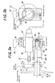
- FIGs. 3(a) and (b) are schematic views respectively showing one embodiment of an end processing apparatus used for a method of producing a polymer insulator according to the invention.
- an end processing apparatus 31 comprises: an FRP core holder 32 for holding the FRP core 2; a high-speed air grinder 34 arranged rotatably around the FRP core holder 32 via a bearing 33, whose rotation center is a central axis of the FRP core; and a whetstone 21 having a shape of an outer surface for forming the protrusion portion 11 and arranged rotatably to the high-speed air grinder 34 at its central axis.
- the high-speed air grinder 34 is secured to a grinder holder 36 via an eccentric bush 37, and it is fixed to the eccentric bush 37 by means of a setscrew 38.
- the end processing apparatus 31 can take a fine machining position during a processing state and an idling state during a non-processing state by varying a position of the eccentric bush 37 in the grinder holder 36 by means of a finger grip 39.
- the eccentric bush 37 can stop at any position between the fine machining position and the idling position by screwing the knob 35 at arbitrary positions.
- a numeral 40 is a holder fix pin and a numeral 41 is a stopper.
- the end portion processing by using the end processing apparatus 31 having the construction mentioned above is as follows.
- the processing steps (3)-(9) require about 5 minutes with respect to the FRP core 2 having a diameter of 24 mm.
- the diameter A of the large diameter portion 12 is increased or decreased or becomes eccentric corresponding to whether the shed removing is performed carefully or not or whether a relation between the FRP core 2 and the overcoat member 3 is eccentric or not.
- an amount of grinding is varied. Therefore, a time required for performing the processing steps mentioned above is varied correspondingly.
- an eccentric amount of the eccentric bush 37 is 4 mm, and thus a stroke of the whetstone 21 from the fine machining position to the idling position is defined as 8 mm. Therefore, the diameter A of the large diameter portion 12 is defined within this range.
- the polymer insulator formed body which is cut out to a predetermined length and wherein the overcoat member 3 of the FRP exposed portion is removed and cleaned, is set on a suitable base horizontally and is not rotated itself while the whetstone 21 is rotated around the FRP core 2.
- a long rod insulator is shown as one embodiment of the polymer insulator.
- a diameter of the FRP core 2 is not limited, and thus the present invention can be applied to another insulators such as LP insulator and hollow porcelain.
- the whetstone 21 it is better to use a diamond whetstone in which diamond powders are electrodeposited on a metal base due to its practicability, but it is not limited.
- the ring-shaped protrusion portion is formed integrally with the overcoat member by processing the end portion of the overcoat member. Therefore, it is possible to vary easily a shape of and the number of protrusion portion to be formed.
- the producing method further includes the steps of: cutting the overcoat member of the polymer insulator to a predetermined length; and processing an end portion of the thus cut overcoat member; so that the ring-shaped protrusion portion and the overcoat member are integrally formed. In this case, it is possible to obtain the polymer insulator having a predetermined length from the ready-made polymer insulator or the stocked polymer insulator.
- the invention it is possible to deal with a small-rot order and also it is possible to increase a productivity of the polymer insulator by reducing the number of metal mold changing operations. Further, in the end processing apparatus according to the invention, it is possible to perform the processing preferably which it required in the method of producing the polymer insulator according to thee invention.
- the ring-shaped protrusion portion can be formed to the end portion of the overcoat member on the basis of the center of the core. Therefore, it is possible to obtain the ring-shaped protrusion portion which can achieve a better securing, even if the securing, even if the overcoat member is eccentric at the processing position.
Landscapes
- Insulators (AREA)
- Insulating Bodies (AREA)
- Suspension Of Electric Lines Or Cables (AREA)
Abstract
Description
Claims (8)
- A method of producing a polymer insulator having a core, an overcoat member arranged on the core, and a fitting member for securing the core at its both ends, wherein the core and the fitting member are secured under pressure at both ends of the core by contacting a ring-shaped protrusion portion arranged at both ends of the overcoat member to an open inner end of the fitting member, comprising the steps of: forming the overcoat member on the core; forming the ring-shaped protrusion portion integrally with the overcoat member by processing an end portion of the overcoat member; and securing the fitting member.
- The method of producing a polymer insulator according to claim 1, wherein a large diameter portion having a diameter larger than that of a sheath portion of the overcoat member is arranged at an end portion of the overcoat member and a ring-shaped protrusion portion having a diameter larger than that of the sheath portion is formed integrally with the overcoat member by processing the large diameter portion.
- The method of producing a polymer insulator according to claim 1, wherein the improvement further comprises the steps of: cutting the overcoat member of the polymer insulator to a predetermined length after the overcoat member is formed on the core; and processing an end portion of the thus cut overcoat member; so that the ring-shaped protrusion portion and the overcoat member are integrally formed.
- The method of producing a polymer insulator according to claim 3, wherein the improvement further comprises the steps of: cutting the overcoat member at a sheath portion thereof when the overcoat member is cut to a predetermined length; arranging a large diameter portion having a diameter larger than that of the sheath portion by cutting a root portion of a shed portion of the overcoat member faced to the cut end portion; and forming a ring-shaped protrusion portion having a diameter larger than that of the sheath portion integrally with the overcoat member by processing the large diameter portion.
- The method of producing a polymer insulator according to claim 1, wherein the overcoat member is produced by forming a sheath portion of the overcoat member on the core, and adhering a shed portion of the overcoat member formed separately with the sheath portion to the sheath portion.
- The method of producing a polymer insulator according to claim 5, wherein a large diameter portion having a diameter larger than that of the sheath portion of the overcoat member is arranged at an end portion of the overcoat member and a ring-shaped protrusion portion having a diameter larger than that of the sheath portion is formed integrally with the overcoat member by processing the large diameter portion.
- An end processing apparatus utilized for the method of producing a polymer insulator according to one of claims 1-6, comprising: a core holder for holding a core; a rotation drive device arranged rotatably around the core holder at a center of a central axis of the core; and a whetstone having a shape for forming an end portion of an overcoat member of the polymer insulator, which is arranged to the rotation drive device rotatably around its center axis; wherein the whetstone itself is rotated and the rotated whetstone is rotated around the end portion of the overcoat member on the core held by the core holder, so that a protrusion portion is formed integrally with the end portion.
- The end processing apparatus according to claim 7, wherein the improvement takes a fine machining position during a whetstone processing state and an idling position during a whetstone non-processing state with respect to the end portion of the overcoat member to which the processing is performed, by utilizing an eccentric bush for securing the rotation drive device.
Applications Claiming Priority (3)
| Application Number | Priority Date | Filing Date | Title |
|---|---|---|---|
| JP2000090418 | 2000-03-29 | ||
| JP2000090418 | 2000-03-29 | ||
| PCT/JP2001/002416 WO2001073798A1 (en) | 2000-03-29 | 2001-03-26 | Method for manufacturing polymer insulator and its end part machining apparatus |
Publications (2)
| Publication Number | Publication Date |
|---|---|
| EP1205948A1 true EP1205948A1 (en) | 2002-05-15 |
| EP1205948A4 EP1205948A4 (en) | 2006-05-10 |
Family
ID=18606027
Family Applications (1)
| Application Number | Title | Priority Date | Filing Date |
|---|---|---|---|
| EP01915783A Ceased EP1205948A4 (en) | 2000-03-29 | 2001-03-26 | Method for manufacturing polymer insulator and its end part machining apparatus |
Country Status (6)
| Country | Link |
|---|---|
| US (1) | US6811732B2 (en) |
| EP (1) | EP1205948A4 (en) |
| JP (1) | JP4549003B2 (en) |
| AU (1) | AU4278501A (en) |
| CA (1) | CA2375608C (en) |
| WO (1) | WO2001073798A1 (en) |
Families Citing this family (4)
| Publication number | Priority date | Publication date | Assignee | Title |
|---|---|---|---|---|
| DE102006004946B4 (en) | 2005-12-08 | 2010-04-29 | BLüCHER GMBH | Functional item of clothing, in particular ABC protective clothing, with integrated measuring device |
| US9929545B2 (en) * | 2013-09-06 | 2018-03-27 | Mitsubishi Electric Corporation | Insulating support for power switchgear |
| CN103700457A (en) * | 2014-01-07 | 2014-04-02 | 平顶山市普汇电气有限责任公司 | Aligning tool for parallelism of novel high pressure disc insulator |
| CN113012871B (en) * | 2021-02-25 | 2022-11-01 | 国网上海市电力公司 | Manufacturing and processing technology of electric power stay insulator |
Family Cites Families (12)
| Publication number | Priority date | Publication date | Assignee | Title |
|---|---|---|---|---|
| DE2746870C2 (en) | 1977-10-19 | 1982-08-26 | Rosenthal Technik Ag, 8672 Selb | Process for the manufacture of composite outdoor insulators |
| FR2459398A1 (en) * | 1979-06-15 | 1981-01-09 | Viennot Pierre | METHOD FOR LOADING RODS IN INSULATING MATERIALS IN CONNECTING FIXTURES AND DEVICE FOR CARRYING OUT SAME |
| PL122159B1 (en) * | 1979-09-15 | 1982-06-30 | Inst Elektrotechniki | High tension overhead-line instulator of plastic materialx and method of manufacturing the samerytykh ustanovok i sposob izgotovlenija plastmassovogo izoljatora vysokogo naprjazhenija dlja otkrytykh ustanovok |
| US5214249A (en) * | 1991-02-22 | 1993-05-25 | Hubbell Incorporated | Electrical assembly with end collars for coupling ends of a weathershed housing to the end fittings |
| JP2588676B2 (en) * | 1992-12-28 | 1997-03-05 | 日本碍子株式会社 | Non-ceramic insulator forming equipment |
| JP2664616B2 (en) * | 1993-03-25 | 1997-10-15 | 日本碍子株式会社 | Airtight structure of non-ceramic insulator |
| DE4421343A1 (en) * | 1994-06-17 | 1995-12-21 | Hoechst Ceram Tec Ag | High voltage ceramic insulator |
| JPH09153315A (en) * | 1995-11-30 | 1997-06-10 | Ngk Insulators Ltd | Composite porcelain pipe and method for manufacturing composite porcelain pipe |
| JP3157710B2 (en) * | 1996-02-29 | 2001-04-16 | 日本碍子株式会社 | Polymer LP insulator and method of manufacturing the same |
| JPH09259673A (en) * | 1996-03-18 | 1997-10-03 | Ngk Insulators Ltd | Method for manufacturing composite insulator |
| JPH10321067A (en) * | 1997-05-23 | 1998-12-04 | Arai Pump Mfg Co Ltd | Polymer insulator |
| US6282783B1 (en) * | 1999-04-09 | 2001-09-04 | Ngk Insulators, Ltd. | Composite electrical insulator, method of assembling same and method of manufacturing same |
-
2001
- 2001-03-26 US US09/979,855 patent/US6811732B2/en not_active Expired - Lifetime
- 2001-03-26 CA CA002375608A patent/CA2375608C/en not_active Expired - Lifetime
- 2001-03-26 WO PCT/JP2001/002416 patent/WO2001073798A1/en not_active Ceased
- 2001-03-26 JP JP2001571429A patent/JP4549003B2/en not_active Expired - Lifetime
- 2001-03-26 EP EP01915783A patent/EP1205948A4/en not_active Ceased
- 2001-03-26 AU AU42785/01A patent/AU4278501A/en not_active Abandoned
Also Published As
| Publication number | Publication date |
|---|---|
| AU4278501A (en) | 2001-10-08 |
| CA2375608A1 (en) | 2001-10-04 |
| US20020149130A1 (en) | 2002-10-17 |
| CA2375608C (en) | 2004-08-03 |
| US6811732B2 (en) | 2004-11-02 |
| EP1205948A4 (en) | 2006-05-10 |
| JP4549003B2 (en) | 2010-09-22 |
| WO2001073798A1 (en) | 2001-10-04 |
Similar Documents
| Publication | Publication Date | Title |
|---|---|---|
| JP3650109B2 (en) | Polishing method of optical fiber ferrule | |
| US4384431A (en) | Methods of and apparatus for preparing an end portion of a lightguide fiber | |
| US5464361A (en) | Method of making fiber termination | |
| EP2519847B1 (en) | Ferrules having an anti-rotation feature and fiber optic connectors using the same | |
| CA2375608C (en) | Method of producing polymer insulator and end processing apparatus utilized for this method | |
| US6048104A (en) | Ferrule for use in optical fiber connector | |
| US4738055A (en) | Methods of adjusting optical fiber connector components | |
| US5123072A (en) | Optical fiber connector terminal and method of making same | |
| JPWO2001073798A1 (en) | Polymer insulator manufacturing method and end processing device used therefor | |
| DE1652217A1 (en) | Lens holder | |
| CN1088154A (en) | On molding tool, make toric method | |
| JP2001047345A (en) | Pore processing method | |
| EP0457282B1 (en) | Optical fiber connector terminal and method of making same | |
| US12447702B2 (en) | Method and assembly for forming an intraocular lens | |
| JPH10300981A (en) | How to Adjust a Polymer Light Guide with Plug Pins | |
| US4200136A (en) | Method for making an optical waveguide coating die | |
| EP0457266A2 (en) | Optical fiber connector terminal and method of making same | |
| CN113749824B (en) | Stainless steel screw head for fixing artificial heart valve and manufacturing method thereof | |
| JP2001116929A (en) | Optical fiber ribbon separator | |
| JPS62292634A (en) | Processing method for lens stock | |
| EP3930127A1 (en) | Coaxial cable outer jacket stripping and tapering machine | |
| JP2005088351A (en) | Mold manufacturing method and mold | |
| US5111521A (en) | Optical fiber connector terminal and method of making same | |
| JP2003098380A (en) | Diameter conversion ferrule, processing method thereof, and optical component using the same | |
| JP4139278B2 (en) | Optical communication sleeve and processing method thereof |
Legal Events
| Date | Code | Title | Description |
|---|---|---|---|
| PUAI | Public reference made under article 153(3) epc to a published international application that has entered the european phase |
Free format text: ORIGINAL CODE: 0009012 |
|
| 17P | Request for examination filed |
Effective date: 20020304 |
|
| AK | Designated contracting states |
Kind code of ref document: A1 Designated state(s): AT BE CH CY DE DK ES FI FR GB GR IE IT LI LU MC NL PT SE TR |
|
| AX | Request for extension of the european patent |
Free format text: AL;LT;LV;MK;RO;SI |
|
| RBV | Designated contracting states (corrected) |
Designated state(s): FR |
|
| REG | Reference to a national code |
Ref country code: DE Ref legal event code: 8566 |
|
| A4 | Supplementary search report drawn up and despatched |
Effective date: 20060327 |
|
| 17Q | First examination report despatched |
Effective date: 20140110 |
|
| STAA | Information on the status of an ep patent application or granted ep patent |
Free format text: STATUS: THE APPLICATION HAS BEEN REFUSED |
|
| 18R | Application refused |
Effective date: 20160320 |