-
The present invention relates to a shipping container for shipping radioactive
materials such as low enriched uranium powder, pellets and scrap material
and particularly relates to a shipping container for radioactive materials having
improved protection for the radioactive materials, as well as affording shipping
economy.
-
Over the years, various types of shipping containers have been designed
specifically for shipping radioactive materials, for example, low enrichment
uranium oxide powder, pellets or radioactive scrap. One form of prior
shipping containers essentially comprised 55-gallon drum-type vessels with
inner steel compartments for two 5-gallon pails of radioactive material.
Experience with these containers, and over time, have brought to the fore
certain problems associated with their use. For example, such shipping
containers were typically fabricated from standard 18-gauge carbon steel and
the product pails were standard 24-gauge carbon steel. Not only were the
containers and pails susceptible to rust and corrosion, but were also
susceptible to denting and deformation due to routine industrial handling.
Further, those early designs were not sized for optimal loading into currently
commercial sea vans. This not only reduced the amount of floor space that
could be efficiently used in sea vans but it also required additional bracing
and supports to keep the containers from shifting during transport.
-
Additionally, new regulations, both in the United States and abroad, relating to
the shipment of radioactive materials have required a higher degree of
structural integrity, resistance to fire and watertightness for the containers
than previously applied to older container designs. From the regulatory
perspective, neither the inner container drum nor the radioactive material
product pails should lose their integrity. That is, the sealed inner containment
drum inside the outer drum should not allow contents to leak out or allow
water to leak in. Similarly, the product pails should not allow the radioactive
material contents to spill. A high degree of resistance to fire is also an
important requirement. As a result of the restrictions on structural integrity,
fire resistance and watertightness, the radioactive material-carrying capacity
per drum of older-style containers has been significantly downgraded.
-
More particularly, in certain instances, older containers have been found to
have significant amounts of rust, including rust on the internal surfaces, which
are not capable of inspection without destroying the container. Further, the
insulating material has proven to be difficult to fabricate and install, especially
in a manner to ensure that the insulation is homogeneous without voids or
holes in the region between the inner vessel and outer drum. Further, many
of the fixturing devices such as bolts and other securing devices of the
older-style containers have been fabricated from typical industrial-grade
materials rather than nuclear-grade materials, as consistent with current
regulatory requirements. The size and geometry of the older-style containers
also is not optimal for loading into standardized sea vans. Such older-style
containers achieve a utilization space of only about 38%, while the factor for
the present invention is 57%.
-
The overall regulatory objective of safety for this type of container is
principally to ensure avoidance of any possibility of a criticality accident during
transportation of special nuclear materials. Both the foreign and domestic
regulatory requirements specify that shipping containers for special nuclear
materials must undergo a number of tests, such as drop, burn and water
intrusion tests, the results of which must be taken into consideration in the
safety analysis submitted in support of licensing.
-
A recent effort by the assignee hereof has resulted in a container for
high-density shipment of uranium oxide powder and pellets. Such newer
container design employs stainless steel materials for fabrication with silicon
rubber gaskets and heavy-duty locking rings for positive leak-tight seals. Fire
retardant foam and ceramic fiberboard panel are also employed in such
newer-style container to protect the contents against the effect of accident
and fire. Moreover, the size and geometry is cubical rather than cylindrical
and its inner containers are nine in number, arranged in a 3x3 array. This
newer container is the subject of U.S. patent application Serial No.
09/315,729, titled "Uranium Oxide Shipping Container," filed May 21, 1999
(Attorney Docket 1585-185).
-
In accordance with a preferred embodiment of the present invention, there is
provided a container for shipping radioactive material comprised of an outer
container and an inner containment vessel for receiving and containing
product pails. Particularly, the outer container comprises a generally
cylindrical container open at its upper end. Bolt brackets are arranged about
the inner periphery of the container for receiving bolts to bolt a top onto the
container. The bolt brackets are arranged, preferably in 90° sectors spaced
about the circumference of the container with a pair of brackets straddling the
container's weld seam to reinforce the container when the top is installed. In
addition to bolting the top to the container, a retaining ring clamps the top to
the container, with a bolt securing end lugs of the retainer ring to one another.
The bolt and lugs in the retaining ring are located as close to the outside wall
of the outer drum as possible to avoid breakage of containment should the
container be dropped or impacted.
-
The inner containment vessel is generally cylindrical and has a radially
outwardly directed flange at its open upper end supported by a plurality of
circumferentially spaced gussets to provide strength to the lid-sealing region
of the vessel. A lid is bolted to the flange with a heat-resistant gasket
therebetween to effect a water seal. The vessel also includes a plurality of
spiders or rods which project outwardly, preferably radially, to maintain the
vessel centered within the outer container. Between the inner vessel and the
outer container is a heat retardant polyurethane foam. The foam limits the
maximum temperature the inner containment vessel and its gasket are
subjected to, for example, during a fire. The foam also protects the inner
containment drum from impact forces resulting from drop and impact tests.
Panels formed of neutron-absorbing poisons may also be optionally applied
about the exterior surface of the inner vessel.
-
Upper and lower dunnages are provided at opposite ends of the outer
container. The dunnages comprise foam and ceramic fiberboard panels for
fire resistance. The upper dunnage includes foam disposed between a pair
of circular ceramic fiberboard panels with each having a stainless steel
overlay. A reduced combined stainless steel and ceramic fiberboard panel
underlies the upper dunnage for reception within the lid of the inner vessel to
maintain stability. The lower dunnage is likewise a combination of foam and
ceramic fiberboard panels.
-
The inner containment vessel is permanently fixed within the outer container.
For shipping, product pails are placed inside the inner containment vessel.
When the lid is bolted to the inner vessel, the upper dunnage is disposed
between the lid and the top of the outer container. The upper dunnage is also
provided with circumferential slots to enable the upper dunnage to be lowered
into the container and pass the bolt connections for disposition on top of the
inner vessel container.
-
Further, to improve resistance to fire, a plurality of plastic-filled vent holes are
provided about the outer container and the upper and lower dunnages. The
plastic plugs prevent water intrusion during normal conditions but will melt
away in a fire to vent the container thereby preventing buildup of gases within
the container in the event sufficient heat is supplied to ignite and burn the
foam. Consequently, the vent plugs enhance the structural integrity of the
shipping container in the event of a fire.
-
From the foregoing, it will be appreciated that there are a number of
significant aspects according to a preferred embodiment of the present
invention. For example, the locking retainer ring provides structural integrity
for the top upon impact, but is backed up by the retaining bolts securing the
top. The spiders maintain the inner vessel and, consequently, the pails
containing the radioactive material centered within the outer container,
affording stabilized geometry following the impact and fire tests. The outer
container is provided with closely spaced annular reinforcing ribs adjacent its
top which affords increased shock-absorbing capability and resistance to
impact from above the container. The upper and lower dunnages provide
impact and fire resistance at the opposite ends of the container. Additionally,
all of the materials and fittings are formed of a stainless steel to preclude rust
and corrosion. Dimensionally, and as set forth below, the shipping container
"fits" into sea van containers in a manner to minimize unused sea van
capacity.
-
Further, the shipping container hereof is readily and easily fabricated. To
accomplish this, the lower dunnage is placed in the bottom of the outer
container. A disk assembly is bolted to the flange of the inner vessel with the
outermost disk having a margin extending beyond the flange of the inner
vessel and an outer diameter corresponding to the inner diameter of the outer
container. This margin contains a pair of diametrically opposite openings
enabling injection of foam into the annular space between the inner vessel
and outer container. With the disk assembly applied, the inner vessel is lifted,
located and centered within the outer container resting on the lower dunnage.
U-shaped channels are provided on both the top and bottom of the outer
container and interconnected by tie rods to maintain the inner vessel centered
within the outer container during foaming. The foam may then be applied
through the openings of the margin of the outer disk. After curing, the disk
assembly is removed, the foam maintaining the inner vessel within the outer
container. Vent holes are drilled into the sides, bottom and top of the outer
container, completing the fabrication.
-
In a preferred embodiment according to the present invention, there is
provided a shipping container for radioactive materials comprising an outer,
generally cylindrically-shaped container body having a closed lower end and
an open, upper end, a top for releasable securement to the container body
and closing the open upper end thereof, a generally cylindrical inner
containment vessel generally concentrically disposed in the outer container
body for receiving at least one radioactive material containing pail, the inner
containment vessel having a lid for closing an open upper end thereof, a foam
material between the outer container body and the inner vessel, the inner
vessel having an outwardly directed flange about the open end thereof, a
plurality of circumferentially spaced reinforcing gussets between an outer
surface of the vessel and an underside of the flange for reinforcing the flange,
the lid and the flange having cooperating fastening elements for fastening the
lid and the flange to one another.
-
In a further preferred embodiment according to the present invention, there is
provided a shipping container for radioactive materials comprising an outer,
generally cylindrically-shaped container body having a closed lower end and
an open, upper end, a top for releasable securement to the container body
and closing the upper end thereof, a generally cylindrical inner containment
vessel, generally concentrically disposed in the outer container for receiving
at least one radioactive material containing pail, the vessel having a lid for
closing an open upper end thereof, a foam material between the outer
container and the inner vessel, the inner containment vessel including a
plurality of rods projecting outwardly of the vessel toward the outer container
body and extending into the foam material for maintaining the inner vessel
substantially concentric within the outer container body.
-
In a still further preferred embodiment according to the present invention,
there is provided a shipping container for radioactive materials comprising an
outer, generally cylindrically-shaped container body having a closed lower end
and an open, upper end, a top for releasable securement to the container
body and closing the open upper end thereof, a generally cylindrical inner
containment vessel, generally concentrically disposed in the outer container
body for receiving at least one radioactive material containing pail, the vessel
having a lid for closing an open upper end thereof and a closed lower end, a
foam material between the outer container body and the inner vessel, an
interior dunnage for the outer container body and overlying the inner
containment vessel between the lid thereof and the top for the outer container
body, the interior dunnage including a foam material disposed between upper
and lower metal sheets and ceramic fiberboard panels and an interior
dunnage underlying the inner vessel within the container body, the lower
dunnage including foam material disposed between the closed lower end of
the vessel and the closed lower end of the container body.
-
In a still further preferred embodiment according to the present invention,
there is provided a shipping container for radioactive materials comprising an
outer, generally cylindrically-shaped container body having a closed lower end
and an open, upper end, a top for releasable securement to the container
body and closing the upper end thereof, a generally cylindrical inner
containment vessel, generally concentrically disposed in the outer container
for receiving at least one radioactive material container pail and having a lid
and neutron absorbing material disposed about the inner vessel and within
the outer container body.
-
In a still further preferred embodiment according to the present invention,
there is provided a shipping container for radioactive materials comprising an
outer, generally cylindrically-shaped container body having a closed lower end
and an open, upper end, a top for releasable securement to the container
body and closing the open upper end thereof, a generally cylindrical inner
containment vessel, generally concentrically disposed in the outer container
body for receiving at least one radioactive material containing pail, the vessel
having a lid for closing an open upper end thereof, a heat-resistant
fire-retardant foam material between the outer container body and the inner
vessel and a plurality of vent holes in the outer container body and plugs
sealing the vent holes responsive to a predetermined temperature for opening
the vent holes.
-
In a still further preferred embodiment according to the present invention,
there is provided a method of fabricating a container for shipping radioactive
materials, including an outer, generally cylindrically-shaped container body
having a closed lower end and an open upper end and an inner container for
receiving pails of the radioactive materials, comprising the steps of lining the
lower end of the outer container body with an insulating material, closing the
top of the inner container with a closure member having a peripheral margin
laterally outwardly of the periphery of the inner container, locating the inner
container within the outer container body forming a generally annular space
between the exterior side walls of the inner vessel and interior walls of the
outer container body and injecting a self-extinguishing fire-retardant foam
material through at least one opening in the closure member and into the
annular space.
-
An embodiment of the invention will now be described, by way of example,
with reference to the accompanying drawings, in which:
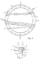
- FIGURE 1 is a cross-sectional view through a central axis of a shipping
container constructed in accordance with a preferred embodiment of the
present invention;
- FIGURE 2 is an enlarged fragmentary cross-sectional view of the part circled
in Figure 1;
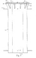
- FIGURE 3 is a side elevational view of an inner containment vessel;
- FIGURE 4 is a top plan view of the inner containment vessel;
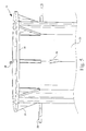
- FIGURE 5 is a fragmentary perspective view of an upper end portion of the
inner containment vessel showing the optional poison panels in place;
- FIGURES 6 and 7 are top and side elevational views of an upper dunnage
between the outer container and inner containment vessel;
- FIGURE 8 is a perspective view of the upper dunnage;
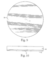
- FIGURES 9 and 10 are bottom and side elevational views of a bottom
dunnage for the shipping container;
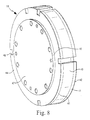
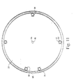
- FIGURE 11 is a top plan view of the shipping container;
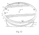
- FIGURE 12 is a perspective view of an upper end portion of the shipping
container;
- FIGURES 13 and 14 are top and side elevational views, respectively, of an
inner lid for the inner containment vessel;
- FIGURE 15 is a plan view of a gasket for use between the inner lid and inner
containment vessel;
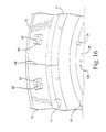
- FIGURE 16 is a fragmentary enlarged view of an upper end portion of the
outer container illustrating the bolt brackets adjacent the seam of the outer
container;
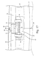
- FIGURE 17 is a fragmentary enlarged perspective view of a clamping ring for
sealing the top of the container to the outer container;
- FIGURE 18 is a fragmentary cross-sectional view illustrating initial fabrication
steps for the shipping container hereof;
- FIGURE 19 is a fragmentary perspective view with parts spaced from one
another for clarity illustrating further steps in the fabrication of the shipping
container hereof; and
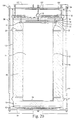
- FIGURE 20 is a vertical cross-sectional view through the shipping container
illustrating the fixtures of the jig for fabricating the shipping container.
-
-
Referring now to the drawings, particularly to Figure 1, there is illustrated a
shipping container constructed in accordance with a preferred embodiment of
the present invention and generally designated 10. Shipping container 10
includes an outer container 12, an inner containment vessel 14 and a pair of
product pails 16 stacked one on top of the other and disposed within the inner
containment vessel 14. Shipping container 10 also includes upper and lower
dunnages 18 and 20, respectively, and a top 22 for the outer container 12.
Outer container 12 is generally cylindrical and preferably fabricated from
stainless steel. Reinforcing ribs 17 are formed at axially spaced locations
along the container 10 and preferably two such ribs are closely spaced to one
another and to the top of the container to reinforce the container, particularly
adjacent the top 22. Also, between the outer container 12 and the inner
containment vessel 14 is provided a heat-retardant foam, preferably a
polyurethane foam 19.
-
Referring now to Figures 3, 4 and 5, the inner containment vessel 14 is
preferably cylindrical, having a bottom 24 and an open top closed by a lid 26.
A plurality of spiders or rods 28 project outwardly, preferably radially, from the
cylindrical containment vessel 14 and into the region between the vessel 14
and outer container 12 to ensure that the vessel remains centered.
Preferably, four rods 28 are equally spaced about the periphery of the vessel
14 adjacent its upper end and a similar number and spacing of the rods are
provided adjacent the lower end of the vessel 14. The rods 28 extend into the
foam which is adhered to the outer container. Consequently, the vessel 14
remains centered within the outer container and is prevented from rotation
relative to the outer container.
-
Additionally, neutron-absorbing material such as cadmium may be provided
about the external surface of the inner vessel 14 in the form of poison panels
29. The panels 29 preferably extend between the top and bottom of the inner
vessel and may be provided in an arcuate length of 90°. The panels overlie
the external peripheral surface of the inner vessel 14 and are provided with
openings to receive the spiders 28, as well as the gussets described below.
The panels 29 as illustrated in Figure 1 are overlaid by the foam 19.
-
An annular flange 30 extends about the periphery of the vessel 14 adjacent
its open upper end and projects radially outwardly therefrom. A plurality of
gussets 32 are disposed between the upper end of the vessel 14 and the
underside of the flange 30 to reinforce the lid sealing region about the open
end of the vessel 14. Lid 26 comprises a circular disk overlying the flange 30
and a gasket 21 formed of a fire retardant material is disposed between the
lid and flange. The lid has a plurality of predrilled holes for registration with
tapped holes in the flange 30 whereby bolts 36 passing through the holes and
threaded into the tapped openings secure the lid and gasket to the vessel 14,
closing its upper end. As illustrated in Figure 5, the flange 30 may also mount
two or more dowel pins 38 to assist in orienting the lid 26 onto the vessel 14
during installation.
-
Referring back to Figure 1, the product pails 16 are preferably formed of
18-20-gauge stainless steel. The product pails are closed containers having
a lid with a retaining ring and bolt about the lid securing the lid to the pail.
The radioactive material is, of course, located in the product pails.
-
Referring now to Figures 6 and 7, the upper dunnage 18 is illustrated. The
upper dunnage comprises a foam core and ceramic fiberboard panels 40 and
41, respectively, sandwiched between a pair of plates 42 and 44, preferably
formed of 24-gauge stainless steel. The plates, as well as the foam and
ceramic fiberboard panels, have cutouts 48 along their margins for receiving
portions of the bolt lugs used to secure the top 22 to the outer container 12
during assembly as described below. Additionally, a circular ceramic
fiberboard panel 46 having an underlayer 47 of stainless steel is secured to
the bottom of the upper dunnage 18 to bear against the lid 26 of the inner
containment vessel 14 in assembly. The lower dunnage 20 illustrated in
Figure 1 is constructed of a similar upper layer of foam 50 underlaid by a
ceramic fiberboard panel 52. The bottom of container 12 is closed by steel
plate 54.
-
Referring now to Figures 11, 12 and 16, the top 22 for the outer container 12
is circular and formed from stainless steel. From a review of Figures 11, 12
and 16, it will be appreciated that top 22 includes a plurality of bolt holes
extending through lugs 60 for threaded engagement with inserts 62 threaded
into bolt brackets 63 secured to the inside surface of the outer container 12.
The bolts 64 are threaded into the inserts 62 to secure the top 22 with a
watertight O-ring seal 61 to the container 12. As seen in Figures 11 and 12,
three of the bolts 64 and associated lugs, plugs and brackets are spaced 90°
from one another about the margin of the top 22. The remaining two bolts are
placed approximately 30° from one another and centered on opposite sides of
a weld seam 68 extending down the side of the outer container 12. Thus, the
bolted connections between the top and the container in the region of the
seam 68 provide added reinforcement for the lid.
-
To supplement the securement of the top 22 to the outer container 12 and as
illustrated in Figures 2 and 17, a heavy-duty retaining ring 70 is applied about
the arcuate rolled edge 72 of the top 22 and a beaded rim 74 formed along
the upper edge of the outer container 12. The ring 70 terminates at opposite
ends in lugs 76 formed to lie close along the outer drum wall rather than
projecting radially so that the extent of the projection of the lugs is minimized
to avoid shearing of the lugs. As illustrated in Figure 17, the wall of the outer
container immediate the area about the lugs is further supported by a
stainless steel plate 81 welded to the outside of the outer drum 12. The steel
plate prevents the bolt lugs from cracking the outer drum weld seam 68 due
to accidental impact. Additionally, a bolt 83 threadedly secures the lugs 76 to
one another. Lock nut 87 keeps the threaded bolt 83 from coming loose
while securing the retaining ring 70 about the margin of top 22 and outer
container 12 to reinforce the securement of the top and outer container one to
the other.
-
A plurality of vent holes 80 (Figure 1) are provided at vertically and
circumferentially spaced positions about the outer container 12. For example,
three vent holes are provided through the container 12 in vertically spaced
relation to one another at 90° intervals about the container 12. Each vent
hole is sealed by a plastic plug 82. Upon reaching a predetermined
temperature, the plastic of the plug 82 melts, opening the vent hole, enabling
the escape of expanding gases from within the container. Additionally, and
referring to Figure 11, the top 22 has a vent hole 84 filled with a plastic plug
86. Likewise, the bottom 54 of the container 12 has a central vent hole and a
plastic plug. The top and bottom vent holes operate similarly as the side vent
holes 80 in Figure 1 to preclude a buildup of pressurized gases within the
container which otherwise might rupture the container. The size and
geometry of the invention is such that a standard sea van can accommodate
up to 72 containers. Older-style containers had sizes and geometries that
would only allow a maximum 54 containers per sea van.
-
Referring now to Figure 18, which illustrates initial fabricating steps for the
shipping container hereof, the bottom 54 of container 12 is provided with a
central hole 90. Next, the ceramic fiberboard panel 52 and the layer of foam
50 of the lower dunnage 20 are placed in the bottom of the outer container
12. A fixture assembly is then provided. The fixture assembly includes a pair
of channel members 92 and 94 connected at their centers to one another by
welding and/or by a bolt 96 and extending at right angles to one another.
Each of the channels has a slot at its distal end for receiving the lower end of
a threaded rod 98. It will be appreciated that four threaded rods 98 are
disposed about the outer container 12 and secured at their lower ends by
nuts 100 to the channel members 92 and 94. The outer container 12 is then
centered within and on the fixture.
-
Referring to Figure 19, a closure member or disk assembly comprised of a
series of disks is disposed on top of the flange 30 of the inner container 14.
In the order placed on the flange 30 of inner vessel 14, the disk assembly
includes a first disk 104 having a plurality of circumferentially spaced bolt
holes 106, vent holes 108 and apertures 110 for receiving the dowel pins 38
formed on the flange 30. Disk 104 is preferably formed of ⅜" thick stainless
steel and has an outer diameter corresponding to the outer diameter of flange
30. The next disk 112 is preferably formed of 22-gauge stainless steel having
bolt holes 114 and vent holes 116. The third disk 118 is preferably formed of
½" thick aluminum and has bolt holes 120 and vent holes 122. From a review
of Figure 19, it will be appreciated that disks 104, 112 and 118 have like
diameters. A final disk 124, preferably formed of ½" thick aluminum, includes
bolt holes 126, vent holes 128 and a pair of openings 130 at diametrically
opposite locations about the disk 124. The diameter of disk 124 is slightly
smaller than the inner diameter of the outer container 12. Additionally, a hook
140 is provided in the center of the top disk 124 for purposes of lifting the
inner container 14. In assembling these disks, the vent holes 108, 116, 122
and 128 are aligned with one another and bolts 132 (Figure 20) extend
through the four disks and thread into correspondingly located threaded bolt
openings 136 (Figure 19) in flange 30. It will be appreciated that the dowel
pins 38 in this assembly are received in the apertures 110 and 111 of the
lower disk 104 and disk 112.
-
Additionally, a quick-release material is provided along the underside of the
margin about the disk 124 which projects beyond the outer diameters of the
disks 104, 112 and 118 to facilitate release of the disk assembly from the
foam, i.e., prevents the foam from sticking to the fixture during the foaming
operation. The inner container 14 with the four disks attached is then lifted,
using hook 140, and located and centered in the outer container 12. In
placing the inner vessel 14 within the outer container 12, it is aligned with the
seam weld 68 along the outer container 12.
-
Levelers, not shown, are placed on top of the disk 124 to ensure that the
inner container is set within the outer container as level as possible. A similar
fixturing assembly like 92, 94, 96 and 100 in Figure 18 is then applied to the
top of the inner and outer containers as illustrated in Figure 20. Particularly, a
pair of channel-shaped elements 150 and 152 are located at right angles to
one another and secured to one another, extending across the open top of
the outer container. The ends of the members 150 and 152 have slots for
receiving the upper ends of the threaded rods 98. The rods are secured in
place by nuts 154. Elongated bolts 156 extend through the members 150
and 152 and their lower ends engage the upper surface of the upper disk
124, ensuring that the inner container remains level within the outer container
12. The container is now ready for the foaming operation. Foam is injected
through the two openings 130 in the upper disk 124 to fill the annular space
between the inner vessel 14 and outer container 12. The foam is injected
simultaneously through holes 130 and fills the annular space to a level
corresponding to an elevation above flange 30 to the bottom side of disk 124,
at which time the foaming operation ceases.
-
After curing, the fixtures, both top and bottom, are removed. Additionally, the
disk assembly is removed from the flange 30 of the inner vessel 14. From a
review of Figure 20, it will be appreciated that the spiders 28 extend into the
foam 19 securing the inner vessel 14 within outer container 12. Next, the bolt
brackets 63 (Figure 16) are drilled and tapped and the inserts 62 are threaded
into the brackets. The brackets 63 are then welded to the inside surface of
the outer container 12, with two of the brackets closely straddling the seam
68. A master template gauge, not shown, may be used to locate the brackets
about the inner circumference of the outer container 12. The backing plate
81 (Figure 17) can also be welded to the outer container at this time. Next, a
template, also not shown, may be used to locate the lugs 60 (Figure 12) and
holes for drilling through the top 22 for the outer container 12. Additionally,
the template may be used to locate the center vent hole 84 in top 22. The
lugs 60 are then welded to the top 22. The ceramic fiberboard panel 52 is
pre-drilled with a central opening through the openings 84 and 90 in the top
and bottom of the outer container 12. A plug 86 is installed in these
openings, the bottom one of which is inserted prior to foaming. The upper
dunnage 18 is then located overlying the top of the inner vessel 14 and the
foam 19, the slots 48 being provided to enable the dunnage 18 to pass by the
lugs 63 (Figure 16). Next, the container's top 22 and outer ring 70 is bolted
into place. An opening is drilled through part of the upper dunnage disks 41
and 42 in Figure 7 for venting purposes. Also, a translucent silicone is used
to seal around the lugs 60 on the top of the top 22. An O-ring washer 61
seals bolt 64 to the top 22, making the top 22 completely watertight.
-
It will be appreciated from the foregoing that there has been provided a
shipping container having substantial structural integrity and resistance to fire
and water intrusion as well as a quick and inexpensive method of fabricating
the container. Importantly, the container provides safety from radiation and
criticality while material parts of the shipping container are formed of materials
resistant to rust and corrosion, such as stainless steel, whereby the integrity
of the container can be maintained over long periods of time and in hundreds
of shipments. The structural integrity of the container is enhanced by the
retaining ring, the spiders or rods which maintain the inner vessel centered
within the outer container and the engagement of the upper and lower
dunnages against the top and bottom of the inner vessel, respectively, the
dunnages being sandwiched between the vessel and the top and bottom of
the container. The arrangement of the reinforcing ribs on the outer container,
particularly adjacent the top of the container, reinforce the top of the
container, enhancing its resistance to impact. Fire resistance is provided by
the combination of foam and ceramic fiberboard panels. Resistance to the
destructive effects of high temperatures is also provided by the provision of
vent holes disposed and arranged to vent any gases generated within the
container upon the container reaching a predetermined temperature. That is,
the plastic plugs melt at high temperature and enable the container to be
vented. Further, the use of bolt brackets with removably threaded inserts
improves the life cycle of the container by permitting the inserts to be
removed and replaced by fresh threaded inserts. Consequently, any damage
to the bolts or female threads may be readily repaired.
-
For completeness, various aspects of the invention are set out in the following
numbered clauses:
- 1. A shipping container (10) for radioactive materials comprising:
- an outer, generally cylindrically-shaped container body (12) having a
closed lower end and an open, upper end;
- a top (22) for releasable securement to the container body and closing
said open upper end thereof;
- a generally cylindrical inner containment vessel (14) generally
concentrically disposed in said outer container body for receiving at least one
radioactive material containing pail (16), said vessel having a lid (26) for
closing an open upper end thereof;
- a foam material (19) between said outer container body and said inner
vessel;
- said inner vessel having an outwardly directed flange (30) about said
open end thereof;
- a plurality of circumferentially spaced reinforcing gussets (32) between
an outer surface of said vessel and an underside of said flange for reinforcing
said flange;
- said lid and said flange having cooperating fastening elements (36) for
fastening said lid and said flange to one another.
- 2. A shipping container according to Clause 1 including a gasket (21)
formed of heat- and fire-resistant material disposed between said lid and said
flange, said foam material comprising a self-extinguishing fire-retardant
material.
- 3. A shipping container according to Clause 1 wherein said inner
containment vessel includes a plurality of rods (28) projecting outwardly of
said vessel toward said outer container body and extending into the foam
material for maintaining said inner vessel substantially concentric within said
outer container body.
- 4. A shipping container according to Clause 3 wherein said rods project
generally radially from said vessel adjacent upper and lower ends of said
vessel and at circumferentially spaced locations about said vessel.
- 5. A shipping container according to Clause 1 including an interior
dunnage (18) for said outer container body and overlying the inner
containment vessel between said lid thereof and said top for said outer
container body, said interior dunnage including a foam material (40) disposed
between ceramic fiberboard panels and upper and lower metal sheets (42,
44).
- 6. A shipping container according to Clause 1 wherein said outer
container body has a plurality of circumferentially spaced bolt brackets (63)
adjacent said top for receiving bolts (64) passed through the top and into the
brackets.
- 7. A shipping container according to Clause 6 wherein said outer
container body has a seam (68), a plurality of said bolts being uniformly
spaced about said lid and a pair of said bolts straddling said seam and being
spaced from one another a distance less than the uniform spacing between
said plurality of bolts.
- 8. A shipping container according to Clause 6 including an interior
dunnage (18) for said outer container body and overlying the inner
containment vessel between said lid of said vessel and said top for said outer
container body, said interior dunnage including a foam material (40) disposed
between ceramic fiberboard panels and upper and lower metal sheets (42,
44) and having a plurality of circumferentially spaced slots (48) opening
through a periphery thereof.
- 9. A shipping container according to Clause 1 including a retaining ring
(70) clamping said top to a radially outwardly extending edge (72) of said
container body, said ring having end lugs (76) bolted to one another.
- 10. A shipping container according to Clause 1 including a plurality of vent
holes (80) in said outer container body and plugs (82) sealing said vent holes
responsive to a predetermined temperature for opening said vent holes.
- 11. A shipping container according to Clause 1 including a plurality of
reinforcing ribs (17) spaced axially from one another along the outer container
body, and a pair of said ribs lying closely adjacent one another and to the
open end of the container body for reinforcing the upper end of the container
body.
- 12. A shipping container according to Clause 1 including neutron
absorbing material (29) disposed about said inner vessel and within the outer
container body.
- 13. A shipping container according to Clause 1 including a retaining ring
(70) clamping said top to a radially outwardly extending edge (72) of said
container body, said ring having end lugs (76) bolted to one another, and a
set of bolts and lugs on the top and outer container body for securing the top
and the container body to one another.
- 14. A shipping container according to Clause 1 wherein said outer
container body has a seam along a side thereof, a metal reinforcement plate
overlying said seam to preclude rupture of said seam upon impact.
- 15. A shipping container for radioactive materials comprising:
- an outer, generally cylindrically-shaped container body (12) having a
closed lower end and an open, upper end;
- a top (22) for releasable securement to the container body and closing
said upper end thereof;
- a generally cylindrical inner containment vessel (14), generally
concentrically disposed in said outer container for receiving at least one
radioactive material containing pail, said vessel having a lid (26) for closing an
open upper end thereof;
- a foam material (19) between said outer container and said inner
vessel;
- said inner containment vessel including a plurality of rods (28)
projecting outwardly of said vessel toward said outer container body and
extending into the foam material for maintaining said inner vessel
substantially concentric within said outer container body.
- 16. A shipping container according to Clause 15 wherein said rods project
generally radially from said vessel adjacent upper and lower ends thereof and
are circumferentially spaced from one another.
- 17. A shipping container according to Clause 15 including interior dunnage
(18) for said outer container body and overlying the inner containment vessel
between said lid and said top for said outer container body, said interior
dunnage including a foam material (40) disposed between upper and lower
metal sheets (42, 44) and ceramic fiberboard panels.
- 18. A shipping container according to Clause 15 wherein said outer
container body has a plurality of circumferentially spaced bolt brackets (63)
adjacent said top for receiving bolts (64) passed through the top and into the
brackets.
- 19. A shipping container according to Clause 15 including a retaining ring
(70) for clamping said top to a radially outwardly extending flange of said
container body, said ring having end lugs (76) bolted to one another.
- 20. A shipping container according to Clause 15 including a plurality of
vent holes (80) in said outer container body and plugs (82) sealing said vent
holes responsive to a predetermined temperature for opening said vent holes.
- 21. A shipping container according to Clause 15 including neutron
absorbing material (29) disposed about said inner vessel and within the outer
container body.
- 22. A shipping container for radioactive materials comprising:
- an outer, generally cylindrically-shaped container body (12) having a
closed lower end and an open, upper end;
- a top (22) for releasable securement to the container body and closing
said open upper end thereof;
- a generally cylindrical inner containment vessel (14), generally
concentrically disposed in said outer container body for receiving at least one
radioactive material containing pail (16), said vessel having a lid (26) for
closing an open upper end thereof and a closed lower end;
- a foam material (19) between said outer container body and said inner
vessel;
- an interior dunnage (18) for said outer container body and overlying the
inner containment vessel between said lid thereof and said top for said outer
container body, said interior dunnage including a foam material (40) disposed
between upper and lower metal sheets (42, 44) and ceramic fiberboard
panels; and
- an interior dunnage (20) underlying said inner vessel within said
container body, said lower dunnage including foam material (50) disposed
between said closed lower end of said vessel and said closed lower end of
said container body.
- 23. A shipping container according to Clause 22 wherein said outer
container body has a plurality of circumferentially spaced bolt brackets (63)
adjacent said top for receiving bolts (64) passed through the top and into the
brackets.
- 24. A shipping container according to Clause 22 including a retaining ring
(70) clamping said top to a radially outwardly extending edge (72) of said
container body, said ring having end lugs (76) bolted to one another.
- 25. A shipping container according to Clause 22 including a plurality of
vent holes (80) in said outer container body and plugs (82) sealing said vent
holes and responsive to a predetermined temperature for opening said vent
holes.
- 26. A shipping container according to Clause 22 including a plurality of
reinforcing ribs (17) spaced axially from one another along the outer container
body, and a pair of said ribs lying closely adjacent one another and to the
open end of the container body for reinforcing the upper end of the container
body.
- 27. A shipping container according to Clause 22 including neutron
absorbing material (29) disposed about said inner vessel and within the outer
container body.
- 28. A shipping container (10) for radioactive materials comprising:
- an outer, generally cylindrically-shaped container body (12) having a
closed lower end and an open, upper end;
- a top (22) for releasable securement to the container body and closing
said upper end thereof;
- a generally cylindrical inner containment vessel (14), generally
concentrically disposed in said outer container for receiving at least one
radioactive material container pail (16) and having a lid (26); and
- neutron absorbing material (29) disposed about said inner vessel and
within the outer container body.
- 29. A shipping container according to Clause 28 including a foam material
(19) between said outer container and said inner vessel, said inner
containment vessel including a plurality of rods (28) projecting outwardly of
said vessel toward said outer container body and extending into the foam
material for maintaining said inner vessel substantially concentric within said
outer container body.
- 30. A shipping container according to Clause 28 including a retaining ring
(70) clamping said top to a radially outwardly extending edge (72) of said
container body, said ring having end lugs (76) bolted to one another.
- 31. A shipping container according to Clause 28 including a plurality of
vent holes (80) in said outer container body and plugs (82) sealing said vent
holes responsive to a predetermined temperature for opening said vent holes.
- 32. A shipping container according to Clause 28 including a plurality of
reinforcing ribs (17) spaced axially from one another along the outer container
body, and a pair of said ribs lying closely adjacent one another and to the
open end of the container body for reinforcing the upper end of the container
body.
- 33. A shipping container for radioactive materials comprising:
- an outer, generally cylindrically-shaped container body (12) having a
closed lower end and an open, upper end;
- a top (22) for releasable securement to the container body and closing
said open upper end thereof;
- a generally cylindrical inner containment vessel (14), generally
concentrically disposed in said outer container body for receiving at least one
radioactive material containing pail (16), said vessel having a lid (26) for
closing an open upper end thereof;
- a heat-resistant, fire-retardant foam material (19) between said outer
container body and said inner vessel; and
- a plurality of vent holes (80) in said outer container body and plugs (82)
sealing said vent holes responsive to a predetermined temperature for
opening said vent holes.
- 34. A shipping container according to Clause 33 an interior dunnage (18)
for said outer container body and overlying the inner containment vessel
between said lid thereof and said top for said outer container body, said
interior dunnage including a heat-resistant, fire-retardant foam material (40)
disposed between upper and lower metal sheets and ceramic fiberboard
panels and an interior dunnage underlying said inner vessel within said
container body, said lower dunnage including foam material (50) and a
ceramic fiberboard panel disposed between said closed lower end of said
vessel and said closed lower end of said container body.
- 35. A method of fabricating a container (10) for shipping radioactive
materials, including an outer, generally cylindrically-shaped container body
(12) having a closed lower end and an open upper end and an inner container
(14) for receiving pails (16) of the radioactive materials, comprising the steps
of:
- lining the lower end (20) of the outer container body with an insulating
material;
- closing the top of the inner container with a closure member (124)
having a peripheral margin laterally outwardly of the periphery of the inner
container;
- locating the inner container within the outer container body forming a
generally annular space between the exterior side walls of the inner vessel
and interior walls of the outer container body; and
- injecting a self-extinguishing fire-retardant foam material (19) through
at least one opening in the closure member and into the annular space.
- 36. A method according to Clause 35 including forming vent holes (80) in
the outer container body.
- 37. A method according to Clause 35 including applying projections (28)
on the walls of the inner container for projecting into the annular space for
envelopment by the foam, thereby fixing the inner container relative to the
outer container body.
-