EP1205566A1 - Hydrogen absorbing alloy and method for its production - Google Patents
Hydrogen absorbing alloy and method for its production Download PDFInfo
- Publication number
- EP1205566A1 EP1205566A1 EP01919866A EP01919866A EP1205566A1 EP 1205566 A1 EP1205566 A1 EP 1205566A1 EP 01919866 A EP01919866 A EP 01919866A EP 01919866 A EP01919866 A EP 01919866A EP 1205566 A1 EP1205566 A1 EP 1205566A1
- Authority
- EP
- European Patent Office
- Prior art keywords
- hydrogen storage
- storage material
- alloy
- molten metal
- flaky
- Prior art date
- Legal status (The legal status is an assumption and is not a legal conclusion. Google has not performed a legal analysis and makes no representation as to the accuracy of the status listed.)
- Granted
Links
Images


Classifications
-
- H—ELECTRICITY
- H01—ELECTRIC ELEMENTS
- H01M—PROCESSES OR MEANS, e.g. BATTERIES, FOR THE DIRECT CONVERSION OF CHEMICAL ENERGY INTO ELECTRICAL ENERGY
- H01M4/00—Electrodes
- H01M4/02—Electrodes composed of, or comprising, active material
- H01M4/36—Selection of substances as active materials, active masses, active liquids
- H01M4/38—Selection of substances as active materials, active masses, active liquids of elements or alloys
- H01M4/383—Hydrogen absorbing alloys
-
- B—PERFORMING OPERATIONS; TRANSPORTING
- B22—CASTING; POWDER METALLURGY
- B22F—WORKING METALLIC POWDER; MANUFACTURE OF ARTICLES FROM METALLIC POWDER; MAKING METALLIC POWDER; APPARATUS OR DEVICES SPECIALLY ADAPTED FOR METALLIC POWDER
- B22F1/00—Metallic powder; Treatment of metallic powder, e.g. to facilitate working or to improve properties
- B22F1/06—Metallic powder characterised by the shape of the particles
-
- B—PERFORMING OPERATIONS; TRANSPORTING
- B22—CASTING; POWDER METALLURGY
- B22F—WORKING METALLIC POWDER; MANUFACTURE OF ARTICLES FROM METALLIC POWDER; MAKING METALLIC POWDER; APPARATUS OR DEVICES SPECIALLY ADAPTED FOR METALLIC POWDER
- B22F9/00—Making metallic powder or suspensions thereof
- B22F9/02—Making metallic powder or suspensions thereof using physical processes
- B22F9/06—Making metallic powder or suspensions thereof using physical processes starting from liquid material
- B22F9/08—Making metallic powder or suspensions thereof using physical processes starting from liquid material by casting, e.g. through sieves or in water, by atomising or spraying
- B22F9/10—Making metallic powder or suspensions thereof using physical processes starting from liquid material by casting, e.g. through sieves or in water, by atomising or spraying using centrifugal force
-
- Y—GENERAL TAGGING OF NEW TECHNOLOGICAL DEVELOPMENTS; GENERAL TAGGING OF CROSS-SECTIONAL TECHNOLOGIES SPANNING OVER SEVERAL SECTIONS OF THE IPC; TECHNICAL SUBJECTS COVERED BY FORMER USPC CROSS-REFERENCE ART COLLECTIONS [XRACs] AND DIGESTS
- Y02—TECHNOLOGIES OR APPLICATIONS FOR MITIGATION OR ADAPTATION AGAINST CLIMATE CHANGE
- Y02E—REDUCTION OF GREENHOUSE GAS [GHG] EMISSIONS, RELATED TO ENERGY GENERATION, TRANSMISSION OR DISTRIBUTION
- Y02E60/00—Enabling technologies; Technologies with a potential or indirect contribution to GHG emissions mitigation
- Y02E60/10—Energy storage using batteries
-
- Y—GENERAL TAGGING OF NEW TECHNOLOGICAL DEVELOPMENTS; GENERAL TAGGING OF CROSS-SECTIONAL TECHNOLOGIES SPANNING OVER SEVERAL SECTIONS OF THE IPC; TECHNICAL SUBJECTS COVERED BY FORMER USPC CROSS-REFERENCE ART COLLECTIONS [XRACs] AND DIGESTS
- Y10—TECHNICAL SUBJECTS COVERED BY FORMER USPC
- Y10S—TECHNICAL SUBJECTS COVERED BY FORMER USPC CROSS-REFERENCE ART COLLECTIONS [XRACs] AND DIGESTS
- Y10S420/00—Alloys or metallic compositions
- Y10S420/90—Hydrogen storage
Definitions
- the present invention relates to a hydrogen storage material and a process for producing the same. More particularly, it relates to a hydrogen storage material which is capable of electrochemically and reversibly storing and releasing hydrogen and shows reduced variations in storage characteristics and service life characteristics, which are important battery characteristics, and also exhibits excellent charge and discharge characteristics and a process for producing the same.
- a hydrogen storage material used in a nickel metal hydride battery is used in the form of a hydrogen storage electrode which is generally prepared by packing a powdered hydrogen storage material, if desired in combination with a binder and a conductive agent, into a three-dimensional porous substrate or applying it to a two-dimensional substrate.
- Hydrogen storage materials that are commonly and widely used in this type of electrodes are of hexagonal crystal form represented by MmNi 5 . These alloys usually have their alloying composition designed to secure characteristics required of electrodes, such as charge and discharge characteristics, storage characteristics, and service life characteristics. For example, the alloys have a high Co content, whereas alloy compositions with a reduced Co content have also been proposed (see JP-A-7-99055 and JP-A-9-213319). It has also been suggested to reduce the amount of Mn and Al dissolved out per specific surface area (see JP-A-11-96999).
- the solidified alloy obtained is as thin as 20 to 50 ⁇ m and is inconvenient to handle in a subsequent heat treatment or grinding.
- the solidification by cooling is unidirectional, the crystals are highly orientated only to have poor initial activity.
- the method has an additional problem of low productivity because the amount of the molten metal that can be dropped is limited considerably.
- the orientation in an alloy could be controlled by reducing the cooling rate, which results in impairment of the alloy structure homogeneity.
- the hydrogen storage materials heretofore proposed have thus encountered with difficulty in securing a service life and storage characteristics of the alloy in consistence with discharge characteristics.
- an object of the present invention is to provide a hydrogen storage material which shows reduced variations in storage characteristics and a life and yet exhibits excellent initial activity and charge and discharge characteristics and to provide a process of producing the same.
- the above object of the present invention is accomplished by the following hydrogen storage material and the following process of producing the same.
- the present invention provides a hydrogen storage material which is characterized by having, as a cast alloy, a flaky or similar shape with a thickness of 50 to 500 ⁇ m and showing such crystallite orientation that the X-ray diffraction pattern has an intensity ratio of plane indices (002)/(200) of 2 to 10 as measured with the cooled surface of the flaky cast alloy being in parallel with a mount.
- the present invention also provides a process for producing a hydrogen storage material as a preferred process for producing the hydrogen storage material of the present invention, which process is characterized by comprising dropping a molten metal in between at least two rotating rolls to make the molten metal to fly three times or more between two of the rolls to rapidly solidify the molten metal by cooling.
- the hydrogen storage material according to the present invention is a cast alloy. It has a flaky shape or a similar shape. If the shape is spherical, the grain size retention in hydrogen absorption and desorption will be reduced. If it has an ingot shape or any other shape, Mn is hardly distributed uniformly in the structure, resulting in reduced anticorrosion characteristics.
- the hydrogen storage material of the present invention has a thickness of 50 to 500 ⁇ m, preferably 50 to 200 ⁇ m. If the thickness is smaller than 50 ⁇ m, the structure, while homogeneous, exhibits appreciable crystal orientation, resulting in reduced initial activity or discharge characteristics. If it exceeds 500 ⁇ m, it will be difficult to eliminate segregation chiefly of Mn from the structure, and corrosion during storage or reduction in battery life can result.
- Orientation of crystallites observed in the present invention is suppressed as compared with a product prepared by a general roll casting method, etc. Because the hydrogen storage material of the present invention is solidified while flying in a zig-zag between at least two rotating rolls, the directions of the surfaces to be cooled are not regular. As a result, the probability of hexagonal crystals having the same a-axis and the same c-axis is relatively low. Such a hydrogen storage material is characterized by superiority in initial electrode activity and discharge characteristics and also in resistance against grain size reduction.
- the hydrogen storage material of the present invention in a non-heat-treated state prefferably has a primary crystal grain size of 20 ⁇ m or smaller.
- the primary crystal grains have a size exceeding 20 ⁇ m, a heat treatment, if conducted for homogenization, fails to eliminate segregation mainly of Ni-Mn, and it is difficult to make the whole structure homogeneous.
- the process of producing a hydrogen storage material according to the present invention comprises dropping a molten metal in between at least two rotating rolls to make the molten metal to fly three times or more between two of the rolls to rapidly solidify the molten metal by cooling.
- the rolls which can be used in the process include Cu-made two rolls.
- the molten metal is made to fly three times or more, preferably 4 or 5 times, between rolls for rapid solidification by cooling. Where the number of flights between rolls for rapid solidification by cooling is two or less, the number of rotation of the rolls must be increased to reduce the thickness, which results in regular crystal orientation. If the thickness is increased enough to nonorientate the crystals, it would be difficult to uniformly distribute Mn, resulting in impairment of the characteristics.
- the rapid solidification by cooling be followed by a heat treatment to reduce compositional fluctuation in the structure or to relax the casting strain.
- fine grain boundary segregations mainly of Mn are found particularly in hydrogen storage materials of MmNi 5 type that are generally used, they are homogenized by a heat treatment.
- a heat treatment for the hydrogen storage material obtained by the process of the present invention completes in an extremely short time as compared with that for alloys obtained by ordinary casting using a mold.
- a heat treatment at 1050°C or lower for 30 minutes or shorter is sufficient.
- the hydrogen storage material according to the present invention is excellent in not only discharge characteristics but grain size retention against repetition of charges and discharges or hydrogen absorption and desorption. Further, being uniform in every site, it has markedly improved life and storage characteristics.
- Raw materials of a hydrogen storage material Mm (misch metal), Al, Mn, Co, Ni, and Cu, were weighed to make an alloy composition of MmAl 0.3 Mn 0.45 Co 0.4 Ni 3.95 and mixed up.
- the mixture was put in a crucible, and the crucible was set in a high frequency melting furnace. After evacuating to a degree of vacuum of 10 -4 to 10 -5 Torr, the mixture was heat melted in an argon gas atmosphere.
- the molten metal was poured at 1500°C in between two water-cooled rolls made of Cu which were disposed at a level difference as shown in Fig. 1 and rotated in reverse directions and made to fly while being cooled between the rolls.
- the number of revolution of the rolls, the pouring rate, and the number of collisions against the cooling surface are shown in Table 1.
- the resulting alloy was subjected to a heat treatment in an argon gas atmosphere under the conditions shown in Table 1 to obtain a flaky hydrogen storage material.
- the thickness of the resulting flaky hydrogen storage material is shown in Table 1.
- Raw materials of a hydrogen storage material Mm (misch metal), Al, Mn, Co, Ni, and Cu, were weighed to make an alloying composition of MmAl 0.3 Mn 0.45 Co 0.4 Ni 3.95 and mixed up.
- the mixture was put in a crucible, and the crucible was set in a high frequency melting furnace. After evacuating to a degree of vacuum of 10 -4 to 10 -5 Torr, the mixture was heat melted in an argon gas atmosphere.
- the molten metal was cast at 1500°C into a Cu-made water-cooled casting mold shown in Fig. 2.
- the rate of pouring is shown in Table 1.
- the resulting alloy was subjected to a heat treatment in an argon gas atmosphere under the conditions shown in Table 1 to obtain a hydrogen storage material ingot.
- Raw materials of a hydrogen storage material Mm (misch metal), Al, Mn, Co, Ni, and Cu, were weighed to make an alloying composition of MmAl 0.3 Mn 0.45 Co 0.4 Ni 3.95 and mixed up.
- the mixture was put in a crucible, and the crucible was set in a high frequency melting furnace. After evacuating to a degree of vacuum of 10 -4 to 10 -5 Torr, the mixture was heat melted in an argon gas atmosphere.
- the molten metal was poured at 1500°C on a rotating water-cooled roll made of Cu shown in Fig. 3. and made to fly while being cooled. The number of revolution of the roll, the pouring rate, and the number of collisions against the cooling surface are shown in Table 1.
- the resulting alloy was subjected to a heat treatment in an argon gas atmosphere under the conditions shown in Table 1 to obtain a flaky hydrogen storage material.
- the thickness of the resulting flaky hydrogen storage material is shown in Table 1.
- Raw materials of a hydrogen storage material Mm (misch metal), Al, Mn, Co, Ni, and Cu, were weighed to make an alloying composition of MmAl 0.3 Mn 0.45 Co 0.4 Ni 3.95 and mixed up.
- the mixture was put in a crucible, and the crucible was set in a high frequency melting furnace. After evacuating to a degree of vacuum of 10 -4 to 10 -5 Torr, the mixture was heat melted in an argon gas atmosphere.
- the molten metal was atomized and cooled with high-pressure argon gas as shown in Fig. 4.
- the pouring rate of the molten metal is shown in Table 1.
- the resulting alloy was subjected to a heat treatment in an argon gas atmosphere under the conditions shown in Table 1 to obtain a spherical hydrogen storage material.
- the alloys of Examples 1 to 5 and Comparative Examples 1 to 5 as cast and heat-treated were subjected to X-ray diffractometry either on the cooled surface and after ground to 20 ⁇ m or smaller sizes. As a result, all the alloy systems had a hexagonal crystal structure of CaCu 5 type.
- the crystal orientation of the alloys prepared was evaluated from the diffraction peak intensity ratio of the (002) plane to the (200) plane, (002)/(200). In nature of powder X-ray diffractometry, the intensity ratio approaches that of a ground state according as the crystals become less orientated. Therefore, the higher the orientation index shown in the Table, the higher the degree of crystallite orientation.
- the powder X-ray diffraction pattern of Comparative Example 3 is shown in Fig.
- the X-ray diffraction patterns of the flaky cast alloys of Comparative Example 4 and Example 3 as measured with the cooled side being in parallel with a mount are shown in Figs. 5(b) and 5(c), respectively.
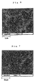
- the characteristic X-ray diffraction pattern (5000 magnifications) of Mn on a cross-section of the hydrogen storage material of Example 3 is shown in Fig. 6, and the characteristic X-ray diffraction pattern (500 magnifications) of Mn on a cross-section of the hydrogen storage material of Comparative Example 3 is shown in Fig. 7.
- a powdered hydrogen storage material having a grain size adjusted to 22 to 53 microns was mixed with prescribed amounts of a conductive agent and a binder.
- the mixed powder was pressed into a pellet electrode, which was used as an anode.
- the pellet anode was combined with a cathode having a sufficient capacity (sintered nickel hydroxide) with a separator interposed therebetween.
- the combined electrodes were dipped in a KOH aqueous solution having a specific gravity of 1.30 to prepare a model cell.
- the cell was subjected to a charge at 0.2C - 130% followed by a discharge at 0.2C - 0.7 V cut-off to measure the discharge capacity.
- a ratio of the measured discharge capacity to the initial discharge capacity after the activation was evaluated as a capacity retention.
- a corrosion behavior in storage was evaluated as follows.
- a classified hydrogen storage material powder was made to absorb hydrogen once for activation by use of a cell for PCT evaluation.
- the cell was put into an aqueous KOH solution having a specific gravity of 1.30 and left to stand as such at 80°C for 4 hours to conduct a dissolution test.
- the amount of the precipitate on the surface and the amount of dissolved alloy components were determined to give a total corrosion.
- the total corrosion was relatively expressed in terms of an index based on that of Comparative Example 3 taken as 100.
- the hydrogen storage material according to the present invention has reduced variations in storage characteristics and life and yet exhibits excellent initial activity and charge and discharge characteristics. Further, the hydrogen storage material can be obtained with satisfactory productivity in high-volume production by the process of the present invention.
Landscapes
- Chemical & Material Sciences (AREA)
- Engineering & Computer Science (AREA)
- Nanotechnology (AREA)
- Chemical Kinetics & Catalysis (AREA)
- Electrochemistry (AREA)
- General Chemical & Material Sciences (AREA)
- Battery Electrode And Active Subsutance (AREA)
- Continuous Casting (AREA)
- Manufacture Of Metal Powder And Suspensions Thereof (AREA)
- Powder Metallurgy (AREA)
- Secondary Cells (AREA)
- Solid-Sorbent Or Filter-Aiding Compositions (AREA)
- Gas Separation By Absorption (AREA)
Abstract
Description
Charge: 0.2 C - 130%; Discharge: 0.2 C - 0.7 V (cut-off)
Cycle: 15 cycles
Temperature: 20°C
Charge: 0.2 C - 130%; Discharge: 1 C - 0.7 V (cut-off)
Temperature: 0°C
Charge: 2 C/3-1h; Discharge: 2 C/3-1h
Cycle: 100 cycles
| Number of Rotation of Roll (m/s) | Pouring Rate (kg/s) | Alloy Thickness (µm) | Number of Collisions | Heat Treating Conditions | |
| Example | |||||
| 1 | 5 | 1 | 300 | 3 | 1030°C/60 min |
| 2 | 10 | 1 | 150 | 4 | 1030°C/30 min |
| 3 | 15 | 2 | 100 | 5 | 1030°C/30 min |
| 4 | 20 | 2 | 80 | 5 | 1000°C/30 min |
| 5 | 25 | 2 | 60 | 5 | 1030°C/5 min |
| Comparative Example | |||||
| 1 | 5 | 3 | 2000 | 2 | 1030°C/60 min |
| 2 | 25 | 0.5 | 30 | 1 | 1030°C/60 min |
| 3 | - | 2 | ingot | - | 1060°C/3 hr |
| 4 | 30 | 0.5 | 30 | 1 | 1030°C/60 min |
| 5 | - | 1 | sphere | - | 1030°C/60 min |

Claims (4)
- A hydrogen storage material which is characterized by having, as a cast alloy, a flaky or similar shape with a thickness of 50 to 500 µm and showing such crystallite orientation that the X-ray diffraction pattern has an intensity ratio of plane indices (002)/(200) of 2 to 10 as measured with the cooled surface of the flaky cast alloy being in parallel with a mount.
- A hydrogen storage material according to claim 1, which has a primary crystal grain size of 20 µm or smaller in a non-heat-treated state.
- A process for producing a hydrogen storage material characterized by comprising dropping a molten metal in between at least two rotating rolls to make said molten metal to fly three times or more between two of said rolls to rapidly solidify said molten metal by cooling.
- A process for producing a hydrogen storage material according to claim 3, wherein the rapidly solidified alloy is heat-treated at 1050°C or lower for 60 minutes or shorter, and then rapidly cooled.
Applications Claiming Priority (3)
| Application Number | Priority Date | Filing Date | Title |
|---|---|---|---|
| JP2000107812A JP4504507B2 (en) | 2000-04-10 | 2000-04-10 | Hydrogen storage alloy and method for producing the same |
| JP2000107812 | 2000-04-10 | ||
| PCT/JP2001/003083 WO2001077397A1 (en) | 2000-04-10 | 2001-04-10 | Hydrogen absorbing alloy and method for its production |
Publications (3)
| Publication Number | Publication Date |
|---|---|
| EP1205566A1 true EP1205566A1 (en) | 2002-05-15 |
| EP1205566A4 EP1205566A4 (en) | 2006-08-30 |
| EP1205566B1 EP1205566B1 (en) | 2008-07-23 |
Family
ID=18620755
Family Applications (1)
| Application Number | Title | Priority Date | Filing Date |
|---|---|---|---|
| EP01919866A Expired - Lifetime EP1205566B1 (en) | 2000-04-10 | 2001-04-10 | Hydrogen absorbing alloy and method for its production |
Country Status (6)
| Country | Link |
|---|---|
| US (1) | US6689233B2 (en) |
| EP (1) | EP1205566B1 (en) |
| JP (1) | JP4504507B2 (en) |
| AT (1) | ATE402270T1 (en) |
| DE (1) | DE60134935D1 (en) |
| WO (1) | WO2001077397A1 (en) |
Families Citing this family (1)
| Publication number | Priority date | Publication date | Assignee | Title |
|---|---|---|---|---|
| JP5250203B2 (en) * | 2006-12-27 | 2013-07-31 | プライムアースEvエナジー株式会社 | Nickel metal hydride storage battery |
Family Cites Families (15)
| Publication number | Priority date | Publication date | Assignee | Title |
|---|---|---|---|---|
| JP3266980B2 (en) * | 1992-05-29 | 2002-03-18 | 住友金属工業株式会社 | Hydrogen storage alloy, method for producing the same, and hydrogen storage alloy electrode |
| MY111637A (en) * | 1992-11-30 | 2000-10-31 | Bhp Steel Jla Pty Ltd | Metal strip casting |
| JP3215235B2 (en) * | 1993-08-17 | 2001-10-02 | 松下電器産業株式会社 | Method for producing hydrogen storage alloy powder and hydrogen storage alloy powder |
| JPH0799055A (en) | 1993-09-29 | 1995-04-11 | Toshiba Battery Co Ltd | Hydrogen secondary battery |
| EP0652601B1 (en) * | 1993-10-08 | 1999-08-18 | Sanyo Electric Co. Ltd | Method for evaluating hydrogen-absorbing alloys for electrode. |
| JPH07320729A (en) * | 1994-05-20 | 1995-12-08 | Sanyo Electric Co Ltd | Hydrogen storage alloy electrode |
| JPH0860265A (en) * | 1994-08-22 | 1996-03-05 | Sumitomo Special Metals Co Ltd | Hydrogen storage alloy thin sheet, alloy powder and production thereof |
| JP3201247B2 (en) | 1996-02-05 | 2001-08-20 | 松下電器産業株式会社 | Sealed alkaline storage battery |
| JPH1196999A (en) | 1997-09-19 | 1999-04-09 | Toshiba Battery Co Ltd | Sealed nickel-hydrogen secondary battery |
| JP3114677B2 (en) | 1997-11-19 | 2000-12-04 | 三井金属鉱業株式会社 | Hydrogen storage alloy and method for producing the same |
| US6268084B1 (en) * | 1997-11-28 | 2001-07-31 | Kabushiki Kaisha Toshiba | Hydrogen-absorbing alloy and secondary battery |
| JP2000144278A (en) | 1998-11-16 | 2000-05-26 | Mitsui Mining & Smelting Co Ltd | Hydrogen storage alloy and method for producing the same |
| JP3493516B2 (en) | 1998-12-15 | 2004-02-03 | 三井金属鉱業株式会社 | Hydrogen storage alloy and method for producing the same |
| JP2000243396A (en) * | 1999-02-23 | 2000-09-08 | Hitachi Ltd | Lithium secondary battery, method of manufacturing the same, negative electrode material thereof, and electric equipment |
| JP4567935B2 (en) * | 1999-12-27 | 2010-10-27 | 株式会社東芝 | Hydrogen storage alloy, secondary battery, hybrid car and electric vehicle |
-
2000
- 2000-04-10 JP JP2000107812A patent/JP4504507B2/en not_active Expired - Lifetime
-
2001
- 2001-04-10 WO PCT/JP2001/003083 patent/WO2001077397A1/en not_active Ceased
- 2001-04-10 AT AT01919866T patent/ATE402270T1/en not_active IP Right Cessation
- 2001-04-10 EP EP01919866A patent/EP1205566B1/en not_active Expired - Lifetime
- 2001-04-10 DE DE60134935T patent/DE60134935D1/en not_active Expired - Lifetime
- 2001-04-10 US US10/009,258 patent/US6689233B2/en not_active Expired - Fee Related
Also Published As
| Publication number | Publication date |
|---|---|
| US20030047254A1 (en) | 2003-03-13 |
| EP1205566B1 (en) | 2008-07-23 |
| ATE402270T1 (en) | 2008-08-15 |
| JP2001294954A (en) | 2001-10-26 |
| WO2001077397A1 (en) | 2001-10-18 |
| JP4504507B2 (en) | 2010-07-14 |
| EP1205566A4 (en) | 2006-08-30 |
| DE60134935D1 (en) | 2008-09-04 |
| US6689233B2 (en) | 2004-02-10 |
Similar Documents
| Publication | Publication Date | Title |
|---|---|---|
| US5840166A (en) | Rare earth metal-nickel hydrogen storage alloy, process for producing the same, and anode for nickel-hydrogen rechargeable battery | |
| US5964968A (en) | Rare earth metal-nickel hydrogen storage alloy, method for producing the same, and anode for nickel-hydrogen rechargeable battery | |
| KR100216305B1 (en) | Rare earth metal-nickel hydrogen storage alloy, preparation method thereof and anode for nickel hydride secondary battery | |
| KR100207906B1 (en) | Age-preciptating rare earth metal-nickel alloy, its manufacture and negative electrode for nickel-hydrogen secondary cell | |
| EP0570957B1 (en) | Rare-earth metal-nickel hydrogen occlusive alloy ingot and method for production thereof | |
| JP2002294373A (en) | Hydrogen storage alloy, production method therefor and negative electrode for nickel-hydrogen secondary battery | |
| US20250128938A1 (en) | Hydrogen storage material, hydrogen storage container, and hydrogen supply apparatus | |
| WO2003054240A1 (en) | Hydrogen storage alloy and hydrogen storage alloy powder, method for production thereof, and negative electrode for nickel-hydrogen secondary cell | |
| CN1075123C (en) | Rare earth metal-nickel series hydrogen absorbing alloy, manufacturing method thereof, and negative electrode for nickel-hydrogen secondary battery | |
| US6689233B2 (en) | Hydrogen absorbing alloy and method for its production | |
| JP5437544B2 (en) | Manufacturing method of negative electrode for secondary battery | |
| EP4019653A1 (en) | Hydrogen storage material, hydrogen storage container, and hydrogen supply device | |
| AU2024306242A1 (en) | Hydrogen storage material, hydrogen storage container, and hydrogen supply device | |
| JP7336038B2 (en) | Hydrogen storage material, hydrogen storage container and hydrogen supply device | |
| US5688341A (en) | Hydrogen-absorbing alloy electrode and method for evaluating hydrogen-absorbing alloys for electrode | |
| JP2001307723A (en) | Negative electrode material for non-aqueous electrolyte secondary battery and method for producing the same | |
| JPH0673466A (en) | Hydrogen storage alloy for Ni-hydrogen battery with excellent electrode life and its manufacturing method | |
| JPH0797648A (en) | Hydrogen storage alloy for battery, manufacturing method thereof, nickel-hydrogen secondary battery | |
| JP2001234261A (en) | Manufacturing method of hydrogen storage alloy | |
| JPS63291363A (en) | Hydrogen absorption alloy | |
| JPH0945322A (en) | Hydrogen storage alloy and hydrogen storage alloy electrode using the same | |
| JP4235721B2 (en) | Hydrogen storage alloy, hydrogen storage alloy electrode, and method for producing hydrogen storage alloy | |
| WO2022230817A1 (en) | Hydrogen storage material, hydrogen storage container, and hydrogen supply apparatus | |
| JPH06228613A (en) | Manufacturing method of granular hydrogen storage alloy | |
| JPH0860265A (en) | Hydrogen storage alloy thin sheet, alloy powder and production thereof |
Legal Events
| Date | Code | Title | Description |
|---|---|---|---|
| PUAI | Public reference made under article 153(3) epc to a published international application that has entered the european phase |
Free format text: ORIGINAL CODE: 0009012 |
|
| 17P | Request for examination filed |
Effective date: 20020212 |
|
| AK | Designated contracting states |
Kind code of ref document: A1 Designated state(s): AT BE CH CY DE DK ES FI FR GB GR IE IT LI LU MC NL PT SE TR |
|
| A4 | Supplementary search report drawn up and despatched |
Effective date: 20060802 |
|
| 17Q | First examination report despatched |
Effective date: 20070803 |
|
| GRAP | Despatch of communication of intention to grant a patent |
Free format text: ORIGINAL CODE: EPIDOSNIGR1 |
|
| GRAS | Grant fee paid |
Free format text: ORIGINAL CODE: EPIDOSNIGR3 |
|
| GRAA | (expected) grant |
Free format text: ORIGINAL CODE: 0009210 |
|
| AK | Designated contracting states |
Kind code of ref document: B1 Designated state(s): AT BE CH CY DE DK ES FI FR GB GR IE IT LI LU MC NL PT SE TR |
|
| REG | Reference to a national code |
Ref country code: GB Ref legal event code: FG4D |
|
| REG | Reference to a national code |
Ref country code: CH Ref legal event code: EP |
|
| REG | Reference to a national code |
Ref country code: IE Ref legal event code: FG4D |
|
| REF | Corresponds to: |
Ref document number: 60134935 Country of ref document: DE Date of ref document: 20080904 Kind code of ref document: P |
|
| NLV1 | Nl: lapsed or annulled due to failure to fulfill the requirements of art. 29p and 29m of the patents act | ||
| PG25 | Lapsed in a contracting state [announced via postgrant information from national office to epo] |
Ref country code: NL Free format text: LAPSE BECAUSE OF FAILURE TO SUBMIT A TRANSLATION OF THE DESCRIPTION OR TO PAY THE FEE WITHIN THE PRESCRIBED TIME-LIMIT Effective date: 20080723 Ref country code: ES Free format text: LAPSE BECAUSE OF FAILURE TO SUBMIT A TRANSLATION OF THE DESCRIPTION OR TO PAY THE FEE WITHIN THE PRESCRIBED TIME-LIMIT Effective date: 20081103 Ref country code: PT Free format text: LAPSE BECAUSE OF FAILURE TO SUBMIT A TRANSLATION OF THE DESCRIPTION OR TO PAY THE FEE WITHIN THE PRESCRIBED TIME-LIMIT Effective date: 20081223 |
|
| PG25 | Lapsed in a contracting state [announced via postgrant information from national office to epo] |
Ref country code: FI Free format text: LAPSE BECAUSE OF FAILURE TO SUBMIT A TRANSLATION OF THE DESCRIPTION OR TO PAY THE FEE WITHIN THE PRESCRIBED TIME-LIMIT Effective date: 20080723 Ref country code: AT Free format text: LAPSE BECAUSE OF FAILURE TO SUBMIT A TRANSLATION OF THE DESCRIPTION OR TO PAY THE FEE WITHIN THE PRESCRIBED TIME-LIMIT Effective date: 20080723 |
|
| PG25 | Lapsed in a contracting state [announced via postgrant information from national office to epo] |
Ref country code: BE Free format text: LAPSE BECAUSE OF FAILURE TO SUBMIT A TRANSLATION OF THE DESCRIPTION OR TO PAY THE FEE WITHIN THE PRESCRIBED TIME-LIMIT Effective date: 20080723 |
|
| PG25 | Lapsed in a contracting state [announced via postgrant information from national office to epo] |
Ref country code: DK Free format text: LAPSE BECAUSE OF FAILURE TO SUBMIT A TRANSLATION OF THE DESCRIPTION OR TO PAY THE FEE WITHIN THE PRESCRIBED TIME-LIMIT Effective date: 20080723 |
|
| PLBE | No opposition filed within time limit |
Free format text: ORIGINAL CODE: 0009261 |
|
| STAA | Information on the status of an ep patent application or granted ep patent |
Free format text: STATUS: NO OPPOSITION FILED WITHIN TIME LIMIT |
|
| 26N | No opposition filed |
Effective date: 20090424 |
|
| PG25 | Lapsed in a contracting state [announced via postgrant information from national office to epo] |
Ref country code: IT Free format text: LAPSE BECAUSE OF FAILURE TO SUBMIT A TRANSLATION OF THE DESCRIPTION OR TO PAY THE FEE WITHIN THE PRESCRIBED TIME-LIMIT Effective date: 20080723 |
|
| REG | Reference to a national code |
Ref country code: CH Ref legal event code: PL |
|
| GBPC | Gb: european patent ceased through non-payment of renewal fee |
Effective date: 20090410 |
|
| PG25 | Lapsed in a contracting state [announced via postgrant information from national office to epo] |
Ref country code: CH Free format text: LAPSE BECAUSE OF NON-PAYMENT OF DUE FEES Effective date: 20090430 Ref country code: LI Free format text: LAPSE BECAUSE OF NON-PAYMENT OF DUE FEES Effective date: 20090430 Ref country code: SE Free format text: LAPSE BECAUSE OF FAILURE TO SUBMIT A TRANSLATION OF THE DESCRIPTION OR TO PAY THE FEE WITHIN THE PRESCRIBED TIME-LIMIT Effective date: 20081023 |
|
| PG25 | Lapsed in a contracting state [announced via postgrant information from national office to epo] |
Ref country code: GB Free format text: LAPSE BECAUSE OF NON-PAYMENT OF DUE FEES Effective date: 20090410 Ref country code: MC Free format text: LAPSE BECAUSE OF NON-PAYMENT OF DUE FEES Effective date: 20090430 Ref country code: IE Free format text: LAPSE BECAUSE OF NON-PAYMENT OF DUE FEES Effective date: 20090410 |
|
| PGFP | Annual fee paid to national office [announced via postgrant information from national office to epo] |
Ref country code: FR Payment date: 20100521 Year of fee payment: 10 |
|
| PG25 | Lapsed in a contracting state [announced via postgrant information from national office to epo] |
Ref country code: GR Free format text: LAPSE BECAUSE OF FAILURE TO SUBMIT A TRANSLATION OF THE DESCRIPTION OR TO PAY THE FEE WITHIN THE PRESCRIBED TIME-LIMIT Effective date: 20081024 |
|
| PG25 | Lapsed in a contracting state [announced via postgrant information from national office to epo] |
Ref country code: LU Free format text: LAPSE BECAUSE OF NON-PAYMENT OF DUE FEES Effective date: 20090410 |
|
| PG25 | Lapsed in a contracting state [announced via postgrant information from national office to epo] |
Ref country code: TR Free format text: LAPSE BECAUSE OF FAILURE TO SUBMIT A TRANSLATION OF THE DESCRIPTION OR TO PAY THE FEE WITHIN THE PRESCRIBED TIME-LIMIT Effective date: 20080723 |
|
| PG25 | Lapsed in a contracting state [announced via postgrant information from national office to epo] |
Ref country code: CY Free format text: LAPSE BECAUSE OF FAILURE TO SUBMIT A TRANSLATION OF THE DESCRIPTION OR TO PAY THE FEE WITHIN THE PRESCRIBED TIME-LIMIT Effective date: 20080723 |
|
| REG | Reference to a national code |
Ref country code: FR Ref legal event code: ST Effective date: 20111230 |
|
| PG25 | Lapsed in a contracting state [announced via postgrant information from national office to epo] |
Ref country code: FR Free format text: LAPSE BECAUSE OF NON-PAYMENT OF DUE FEES Effective date: 20110502 |
|
| PGFP | Annual fee paid to national office [announced via postgrant information from national office to epo] |
Ref country code: DE Payment date: 20200331 Year of fee payment: 20 |
|
| REG | Reference to a national code |
Ref country code: DE Ref legal event code: R071 Ref document number: 60134935 Country of ref document: DE |