EP1205363A1 - Gas generator - Google Patents
Gas generator Download PDFInfo
- Publication number
- EP1205363A1 EP1205363A1 EP00948241A EP00948241A EP1205363A1 EP 1205363 A1 EP1205363 A1 EP 1205363A1 EP 00948241 A EP00948241 A EP 00948241A EP 00948241 A EP00948241 A EP 00948241A EP 1205363 A1 EP1205363 A1 EP 1205363A1
- Authority
- EP
- European Patent Office
- Prior art keywords
- ignitors
- gas
- housing
- airbag
- gas generator
- Prior art date
- Legal status (The legal status is an assumption and is not a legal conclusion. Google has not performed a legal analysis and makes no representation as to the accuracy of the status listed.)
- Granted
Links
Images


Classifications
-
- B—PERFORMING OPERATIONS; TRANSPORTING
- B60—VEHICLES IN GENERAL
- B60R—VEHICLES, VEHICLE FITTINGS, OR VEHICLE PARTS, NOT OTHERWISE PROVIDED FOR
- B60R21/00—Arrangements or fittings on vehicles for protecting or preventing injuries to occupants or pedestrians in case of accidents or other traffic risks
- B60R21/02—Occupant safety arrangements or fittings, e.g. crash pads
- B60R21/16—Inflatable occupant restraints or confinements designed to inflate upon impact or impending impact, e.g. air bags
- B60R21/26—Inflatable occupant restraints or confinements designed to inflate upon impact or impending impact, e.g. air bags characterised by the inflation fluid source or means to control inflation fluid flow
- B60R21/264—Inflatable occupant restraints or confinements designed to inflate upon impact or impending impact, e.g. air bags characterised by the inflation fluid source or means to control inflation fluid flow using instantaneous generation of gas, e.g. pyrotechnic
-
- F—MECHANICAL ENGINEERING; LIGHTING; HEATING; WEAPONS; BLASTING
- F42—AMMUNITION; BLASTING
- F42B—EXPLOSIVE CHARGES, e.g. FOR BLASTING, FIREWORKS, AMMUNITION
- F42B3/00—Blasting cartridges, i.e. case and explosive
- F42B3/10—Initiators therefor
- F42B3/12—Bridge initiators
- F42B3/124—Bridge initiators characterised by the configuration or material of the bridge
-
- B—PERFORMING OPERATIONS; TRANSPORTING
- B60—VEHICLES IN GENERAL
- B60R—VEHICLES, VEHICLE FITTINGS, OR VEHICLE PARTS, NOT OTHERWISE PROVIDED FOR
- B60R21/00—Arrangements or fittings on vehicles for protecting or preventing injuries to occupants or pedestrians in case of accidents or other traffic risks
- B60R21/01—Electrical circuits for triggering passive safety arrangements, e.g. airbags, safety belt tighteners, in case of vehicle accidents or impending vehicle accidents
- B60R21/017—Electrical circuits for triggering passive safety arrangements, e.g. airbags, safety belt tighteners, in case of vehicle accidents or impending vehicle accidents including arrangements for providing electric power to safety arrangements or their actuating means, e.g. to pyrotechnic fuses or electro-mechanic valves
-
- B—PERFORMING OPERATIONS; TRANSPORTING
- B60—VEHICLES IN GENERAL
- B60R—VEHICLES, VEHICLE FITTINGS, OR VEHICLE PARTS, NOT OTHERWISE PROVIDED FOR
- B60R21/00—Arrangements or fittings on vehicles for protecting or preventing injuries to occupants or pedestrians in case of accidents or other traffic risks
- B60R21/02—Occupant safety arrangements or fittings, e.g. crash pads
- B60R21/16—Inflatable occupant restraints or confinements designed to inflate upon impact or impending impact, e.g. air bags
-
- B—PERFORMING OPERATIONS; TRANSPORTING
- B60—VEHICLES IN GENERAL
- B60R—VEHICLES, VEHICLE FITTINGS, OR VEHICLE PARTS, NOT OTHERWISE PROVIDED FOR
- B60R21/00—Arrangements or fittings on vehicles for protecting or preventing injuries to occupants or pedestrians in case of accidents or other traffic risks
- B60R21/02—Occupant safety arrangements or fittings, e.g. crash pads
- B60R21/16—Inflatable occupant restraints or confinements designed to inflate upon impact or impending impact, e.g. air bags
- B60R21/26—Inflatable occupant restraints or confinements designed to inflate upon impact or impending impact, e.g. air bags characterised by the inflation fluid source or means to control inflation fluid flow
-
- B—PERFORMING OPERATIONS; TRANSPORTING
- B60—VEHICLES IN GENERAL
- B60R—VEHICLES, VEHICLE FITTINGS, OR VEHICLE PARTS, NOT OTHERWISE PROVIDED FOR
- B60R21/00—Arrangements or fittings on vehicles for protecting or preventing injuries to occupants or pedestrians in case of accidents or other traffic risks
- B60R21/02—Occupant safety arrangements or fittings, e.g. crash pads
- B60R21/16—Inflatable occupant restraints or confinements designed to inflate upon impact or impending impact, e.g. air bags
- B60R21/26—Inflatable occupant restraints or confinements designed to inflate upon impact or impending impact, e.g. air bags characterised by the inflation fluid source or means to control inflation fluid flow
- B60R21/264—Inflatable occupant restraints or confinements designed to inflate upon impact or impending impact, e.g. air bags characterised by the inflation fluid source or means to control inflation fluid flow using instantaneous generation of gas, e.g. pyrotechnic
- B60R21/2644—Inflatable occupant restraints or confinements designed to inflate upon impact or impending impact, e.g. air bags characterised by the inflation fluid source or means to control inflation fluid flow using instantaneous generation of gas, e.g. pyrotechnic using only solid reacting substances, e.g. pellets, powder
-
- B—PERFORMING OPERATIONS; TRANSPORTING
- B60—VEHICLES IN GENERAL
- B60R—VEHICLES, VEHICLE FITTINGS, OR VEHICLE PARTS, NOT OTHERWISE PROVIDED FOR
- B60R21/00—Arrangements or fittings on vehicles for protecting or preventing injuries to occupants or pedestrians in case of accidents or other traffic risks
- B60R21/02—Occupant safety arrangements or fittings, e.g. crash pads
- B60R21/16—Inflatable occupant restraints or confinements designed to inflate upon impact or impending impact, e.g. air bags
- B60R21/26—Inflatable occupant restraints or confinements designed to inflate upon impact or impending impact, e.g. air bags characterised by the inflation fluid source or means to control inflation fluid flow
- B60R2021/26029—Ignitors
-
- B—PERFORMING OPERATIONS; TRANSPORTING
- B60—VEHICLES IN GENERAL
- B60R—VEHICLES, VEHICLE FITTINGS, OR VEHICLE PARTS, NOT OTHERWISE PROVIDED FOR
- B60R21/00—Arrangements or fittings on vehicles for protecting or preventing injuries to occupants or pedestrians in case of accidents or other traffic risks
- B60R21/02—Occupant safety arrangements or fittings, e.g. crash pads
- B60R21/16—Inflatable occupant restraints or confinements designed to inflate upon impact or impending impact, e.g. air bags
- B60R21/26—Inflatable occupant restraints or confinements designed to inflate upon impact or impending impact, e.g. air bags characterised by the inflation fluid source or means to control inflation fluid flow
- B60R21/263—Inflatable occupant restraints or confinements designed to inflate upon impact or impending impact, e.g. air bags characterised by the inflation fluid source or means to control inflation fluid flow using a variable source, e.g. plural stage or controlled output
- B60R2021/2633—Inflatable occupant restraints or confinements designed to inflate upon impact or impending impact, e.g. air bags characterised by the inflation fluid source or means to control inflation fluid flow using a variable source, e.g. plural stage or controlled output with a plurality of inflation levels
-
- B—PERFORMING OPERATIONS; TRANSPORTING
- B60—VEHICLES IN GENERAL
- B60R—VEHICLES, VEHICLE FITTINGS, OR VEHICLE PARTS, NOT OTHERWISE PROVIDED FOR
- B60R21/00—Arrangements or fittings on vehicles for protecting or preventing injuries to occupants or pedestrians in case of accidents or other traffic risks
- B60R21/02—Occupant safety arrangements or fittings, e.g. crash pads
- B60R21/16—Inflatable occupant restraints or confinements designed to inflate upon impact or impending impact, e.g. air bags
- B60R21/26—Inflatable occupant restraints or confinements designed to inflate upon impact or impending impact, e.g. air bags characterised by the inflation fluid source or means to control inflation fluid flow
- B60R21/264—Inflatable occupant restraints or confinements designed to inflate upon impact or impending impact, e.g. air bags characterised by the inflation fluid source or means to control inflation fluid flow using instantaneous generation of gas, e.g. pyrotechnic
- B60R21/2644—Inflatable occupant restraints or confinements designed to inflate upon impact or impending impact, e.g. air bags characterised by the inflation fluid source or means to control inflation fluid flow using instantaneous generation of gas, e.g. pyrotechnic using only solid reacting substances, e.g. pellets, powder
- B60R2021/2648—Inflatable occupant restraints or confinements designed to inflate upon impact or impending impact, e.g. air bags characterised by the inflation fluid source or means to control inflation fluid flow using instantaneous generation of gas, e.g. pyrotechnic using only solid reacting substances, e.g. pellets, powder comprising a plurality of combustion chambers or sub-chambers
-
- B—PERFORMING OPERATIONS; TRANSPORTING
- B60—VEHICLES IN GENERAL
- B60R—VEHICLES, VEHICLE FITTINGS, OR VEHICLE PARTS, NOT OTHERWISE PROVIDED FOR
- B60R21/00—Arrangements or fittings on vehicles for protecting or preventing injuries to occupants or pedestrians in case of accidents or other traffic risks
- B60R21/01—Electrical circuits for triggering passive safety arrangements, e.g. airbags, safety belt tighteners, in case of vehicle accidents or impending vehicle accidents
- B60R21/017—Electrical circuits for triggering passive safety arrangements, e.g. airbags, safety belt tighteners, in case of vehicle accidents or impending vehicle accidents including arrangements for providing electric power to safety arrangements or their actuating means, e.g. to pyrotechnic fuses or electro-mechanic valves
- B60R21/0173—Diagnostic or recording means therefor
Definitions
- the proposed gas generator is so designed that an elongate cylindrical housing is partitioned into a plurality of combustion chambers and also the gas generating agents in the respective combustion chambers are burnt independently of each other by the respective ignitors (squibs).
- the ignitors are operated (ignited by electrifying thereto) with a time difference so that the gas generating agents in the respective combustion chambers are burnt successively.
- the airbag In the initial stage of inflation, the airbag is expanded and inflated gently or moderately by a small amount of gas generated in a first combustion chamber and then, is expanded and inflated rapidly by a large amount of gas generated in the respective combustion chambers.
- the ill-set of the connectors is likely to happen when connecting between the ignitors (squibs) and the control circuits (control units) for controlling the electrifying the ignitors.
- a gas generator of the present invention is so structured that gas generating agents in a housing are burnt by a plurality of ignitors, that the ignitors electrically ignite ignition agents by use of resistance exothermic bodies for generating heat by electrifying, and that resistance values thereof are differentiated from each other.
- a gas generator of the present invention is so structured that gas generating agents in a plurality of combustion chambers are burnt by a plurality of ignitors independently of each other, that the ignitors electrically ignite ignition agents by use of the resistance exothermic bodies for generating heat by electrifying, and that resistance values thereof are differentiated from each other.
- This can provide an adequately controlled expansion and inflation of the airbag, without reversing the operation order of the ignitors and the combustion order in the combustion chambers, and also can provide an improved reliability in the control.
- the present invention it is possible to differentiate the resistance values of the resistance exothermic bodies by selecting a form or a material thereof.
- the gas generator of the present invention is designed to provide a controlled expansion and inflation of an airbag by burning gas generating agents packed in the housing by use of a plurality of ignitors fitted to the housing.
- a gas generator of the present invention is so structured that the ignitors are electrically ignited by electrifying through the resistance exothermic bodies, and that the resistance values thereof are differentiated from each other, thus making the connection between the respective ignitors and the controller reliable, and that the expansion and inflation of the airbag can be controlled.
- the gas generators of the present invention described herein as examples of use include the one used to expand and inflate the driver-side airbag (FIG. 1) and the one used to expand and inflate the passenger-side airbag or an airbag for a side collision (FIG. 5).
- the gas generator D as shown in FIG. 1 is used to expand and inflate the driver-side airbag.
- the gas generator comprises a short cylindrical housing 1, an inner cylindrical member 2 fitted to the housing 1, a partition member 5 for partitioning an inner space of the inner cylindrical member 2 into two upper and lower combustion chambers 3 and 4, filters 6, gas generating agents 7 packed in the combustion chambers 3 and 4, and two ignitors 8 and 9 for burning the gas generating agents 7 packed in the combustion chambers 3 and 4 independently of each other.
- the housing 1 has a double cylinder structure formed by an upper casing 10 and a lower casing 11.
- the housing 1 is so structured that the respective casings 10, 11 are joined to each other by butt welding (e.g. friction welding) so that an outer cylinder 12 and an inner cylinder 13 can be closed at the upper and lower ends thereof by two cover plates 14, 15.
- butt welding e.g. friction welding
- an outer cylinder 12 and an inner cylinder 13 can be closed at the upper and lower ends thereof by two cover plates 14, 15.
- the interior of the housing 1 is partitioned into a closed space S (annular space) between the outer cylinder 12 and the inner cylinder 13 and a space S1 on the inward side of the inner cylinder 13.
- the outer cylinder 12 of the housing 1 has a plurality of gas discharge holes 12a formed to communicate between the closed space S and outside (interior of the airbag).
- the gas discharge holes 12a open in the outer cylinder 12 at an upper end portion thereof (on the upper cover plate 14 side) and are spaced apart at a given interval along a circumferential direction of the housing 1.
- the gas discharge holes 12a are closed by a burst plate 16 adhered to an inside surface around the outer cylinder 12.
- the bust plate 16 is formed of a metal foil such as aluminum and serves as moisture-proof and inner pressure adjustment of the housing 1.
- the inner cylinder 13 has a plurality of flame spouting holes 13a communicating between the spaces S and S1.
- the flame spouting holes 13a open in the inner cylinder 13 at a upper end portion thereof (on the upper cover plate 14 side) and are spaced apart at a given interval along the circumferential direction of the housing 1.
- the lower cover plate 15 of the housing 1 has a short inner cylinder 18 which is integrally formed to project into the closed space S.
- the short inner cylinder 18 is located at a position between the outer cylinder 12 and the inner cylinder 13, deviating from the axis of the housing 1 (inner cylinder 13) toward the outer cylinder 12.
- the lower cover plate 15 has a flanged cylinder 21 formed around its peripheral margin to extend toward the upper cover plate 14 along an outside diameter of the outer cylinder 12.
- a retainer or equivalent (not shown) of the airbag module (including the airbag and a bag cover) is attached to a flange 22 of the flanged cylinder 21.
- An inner cylindrical member 2 is fitted in the closed space S in the housing 1.
- the inner cylindrical member 2 is produced by forming a metal, such as a perforated metal sheet (punched metal) or an expanded metal, into a cylindrical form.
- the inner cylindrical member 2 is fitted in a space between the outer cylinder 12 and the short inner cylinder 18 and extends from the lower cover plate 15 to a position close to the upper cover plate 14.
- the inner cylindrical member 2 is closed at its upper end by a cover plate ring 23 fitted to the periphery of the inner cylinder 13.
- the space S is partitioned into a gas passage space S2 (annular space) on the outer cylinder 12 side and a combustion space S3 (annular space) on the inner cylinder 13 side by the inner cylindrical member 2.
- the inner cylindrical member 2 has a plurality of gas passage holes 2a communicating between the respective spaces S2 and S3, which are formed by the punched metal or equivalent.
- the combustion space S3 in the inner cylindrical member 2 is partitioned into two upper and lower combustion chambers 3, 4 by the partition member 5.
- the partition member 5 is press-fitted in the inner cylindrical member 2, so that the combustion chamber S3 is partitioned into the combustion chambers 3, 4 in a predetermined volume proportion.
- the partition member 5 is fitted to the periphery of the inner cylinder 13, so that it is positioned above the short inner cylinder 18.
- the filters 6 are fitted in the combustion chambers 3, 4, respectively, and also the gas generating agents 7 are packed in the combustion chambers.
- the filters 6 are produced at a low price, for example, by pressing a knitted wire mesh or an aggregation of crimped metal wire rods into cylindrical shape.
- the filters 6 are fitted in the space between the inner cylindrical member 2 and the short inner cylinder 18, one of which extends from the partition member 5 to the cover plate ring 23 within the combustion chamber 3, and the other of which extends from the lower cover plate 15 to the partition member 5 within the combustion chamber 4.
- the combustion chambers 3, 4 are packed with the gas generating agents 7 from which high temperature gas is generated by burning.
- the gas generating agents 7 packed in the combustion chambers are adjusted in amount so that a controlled expansion and inflation of the airbag can be provided.
- the ignitors 8, 9 are fitted to the inner cylinder 13 and the short inner cylinder 18 of the housing 1, respectively.
- the ignitors 8, 9 are presented in the form of pin-type squibs that make ignition agents 26 to be ignited by the passage of electric current through the bridge wires 24 (resistance exothermic bodies).
- Each ignitor 8, 9 comprises a cup-shaped tubular member 25, the ignition agent 26 contained in the tubular member 25, lead pins 27, 28 for electrify to a bridge wire 24, and a rod-like plug 29.
- the bridge wire 24 and the ignition agent 26 are shielded in the tubular member 25 in the press-contacted condition by the plug 29 fittingly inserted in the tubular member 25.
- the bridge wire 24 is connected to the lead pins 27, 28 in the interior of the tubular member 25, so as to be bridged therebetween.
- the lead pins 27, 28 extend through the plug 29 from the inside of the tubular member 25 and project out to the opposite side of the tubular member 25.
- the tubular member 25 has a fire hole 25a formed to communicate between the interior of the tubular member 25 and the outside.
- the fire hole 25a may be formed as a score which is broken by ignition of the ignition agents 26.
- the ignitors 8, 9 are fitted into the inner cylinders 13, 18 from the projecting side of the lead pins 27, 28, respectively, so that the tubular members 25 are projected into the inner cylinder 13 or the combustion chamber 4.
- the respective lead pins 27, 28 are projected from the inner cylinders 13, 18 to the lower cover plate 15 side to be connected to vehicle-side connectors.
- the ignitor 8 confronts an enhancer agents 17 in the inner cylinder 13.
- the ignitors 8, 9 are fixedly caulked to the inner cylinders 13, 18, respectively, by the caulking projections 31, 32 projecting into the inner cylinder 13 and the combustion chamber 4 being folded radially inwardly.
- the respective ignitor 8, 9 can be discriminated (diagnosed) by differentiating the resistance values R [ ⁇ ] of the bridge wires 24 (resistance exothermic bodies).
- tolerance of resistance value R [ ⁇ ] is ⁇ 0.3 [ ⁇ ].
- the difference of resistance value between the respective ignitors 8, 9 is 0.6 [ ⁇ ] to 2.0 [ ⁇ ].
- the respective ignitors 8, 9 get the bridge wire 24 to generate heat by electrifying to the lead pins 27, 28, and the generation of heat causes the ignition agents 26 to be ignited.
- the flames of the ignition agents 26 are spurted into the inner cylinder 13 and the combustion chamber 4 through the fire holes 25a of the tubular member 25 (See FIG. 2).
- Pigtail squibs other than a pin type squibs can be used for the respective ignitors 8, 9.
- the pigtail squib is formed with lead wires instead of the lead pins 27, 28 shown in FIG. 2 pulling the respective lead wires outside of a housing and mounting gas-generator-side connectors on the tip end of the lead wires.
- the squib is also connected with a control unit 40 (controller) (See FIG. 4) by connecting gas-generator-side connectors to vehicle-side-connectors.
- the gas generator D thus constructed is built in an airbag module fitted in the steering wheel and connected with the control unit shown in FIG. 4.
- the respective ignitors 8, 9 of the gas generator D are connected to vehicle-side-connectors 30 shown in FIG. 2, for example, and connected to a control unit by cables dead wires) of the connectors 30.
- the control unit 40 described above includes a collision sensor (acceleration sensor) 46 for detecting a collision of an automobile, booster circuits 41 for electrifying to the respective ignitors 8, 9 (the bridge wires 24), a back-up condenser 47, a controller formed with squib (ignitor) driving circuits 42a, 42b, and diagnostic circuits for diagnosing disconnection, short circuits and the like, and controls the whole unit with a microcomputer 45.
- the control unit 40 diagnoses a presence of disconnection, for example, by measuring a circuit resistance value [ ⁇ ], a circuit voltage [V] and such.
- a circuit resistance [ ⁇ ] formed with a controller and the ignitor 8 and a circuit resistance value [ ⁇ ] formed with a controller and the ignitor 9 are different from each other. Therefore, if there occurs an ill-set between the respective ignitors 8, 9 and the controller, resistance value, voltage and the like are heightened or lowered compared to those in the regular case. Thus, the ill-set can be diagnosed by the diagnostic circuits 43.
- the diagnostic circuits 43 give feedback to the microcomputer 45 and turn on an alarm light (indicator) 44 to give a notice to operators and the like.
- the operator connects the respective ignitors 8, 9 with the respective squib circuits 42a, 42b adequately by replacing the respective connectors 30.
- the respective ignitors 8, 9 and the controller may be connected after charging the respective of the ignitors 8, 9 beforehand with weak electric current and discriminating (diagnosing) differences of resistance value [ ⁇ ], voltage [V] and the like.
- the gas generator D connected to the control unit 40 operates as follows.
- the ignitor 8 is operated (ignited by electrifying thereto) by the squib driving circuits 42a, to ignite the enhancer agents 17.
- the ignition flame of the enhancer agents 17 is spurted into the combustion chamber 3 (the upper combustion chamber) from the flame spouting holes 13a to get the gas generating agents 7 to be burnt to thereby produce high temperature gas.
- the high temperature gas generated in the combustion chamber 3 flows in the filters 6, first, for slag collection and cooling of the gas thereat, and then flows from the gas passage holes 2a into the gas passage space S2. Then, when the combustion in the combustion chamber 3 proceeds and the pressure in the housing 1 reaches a predetermined pressure, the burst plate 16 is broken, so that clean gas uniformed in the gas passage space S2 is discharged from the gas discharge holes 12a into the airbag (See FIGS. 1 and 5).
- the ignitor 9 is operated (ignited by electrifying thereto) with small time difference from after the start of combustion in the combustion chamber 3 by the squib driving circuits 42b controlled by the microcomputer 45, the ignition flame is spurted into the combustion chamber 4 (the lower combustion chamber) to get the gas generating agents 7 to be burnt to thereby produce high temperature gas.
- the high temperature gas produced in the combustion chamber 4 flows into the filters 6, first, for the slag collection and cooling of the gas thereat, and then flows into the gas passage space S2. Then, the gas that flowed into the gas passage space S2 is discharged from the gas discharging holes 12a into the airbag.
- the airbag is switched to be expanded and inflated rapidly by a large amount of clean gas discharged from the respective combustion chambers 3, 4 (See FIG. 1).
- the airbag starts to be expanded and inflated moderately by a small amount of gas generated in the combustion chamber 3 only, first, and then is expanded and inflated rapidly with a short delay by a large amount of gas generated in the combustion chambers 3, 4.
- the ignitors 8, 9 are not necessarily operated with the small time delay, but may be selectively operated to meet the patterns of automobile collision.
- the ignitors 8, 9 are operated (ignited by electrifying thereto) concurrently so that the airbag can be expanded and inflated rapidly by a large amount of gases generated in the combustion chambers 3, 4.
- the ignitors 8, 9 are operated (ignited by electrifying thereto) with a small time delay so that the airbag can be expanded and inflated moderately by a small amount of gas in the initial stage, first, and then is expanded and inflated rapidly with a short time delay by a large amount of gases.
- the ignitor 8 is operated (ignited by electrifying thereto) so that the airbag can take relatively much time to be expanded and inflated moderately by a small amount of gas.
- an amount of gas generated can be adjusted by adequately selecting the operation of the ignitors 8, 9 (the ignition by electrifying thereto), whereby the expansion and inflation of the airbag can be controlled.
- the ignitors 8, 9 have to be located in the plane of the lower cover plate 15 and thus are susceptible to the ill-connection with the controller caused by the ill-set of the vehicle-side connectors 30.
- the air bag can be expanded and inflated according to the seated posture of the passenger and its intended function can be fulfilled.
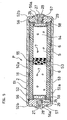
- a gas generator P as shown in FIG. 5 is used to expands and inflates a passenger-side airbag or an air bag for a side collision and includes a long cylindrical housing 51, the inner cylindrical member 2 mounted in the housing 51, a partition member 55 for partitioning an inside of the inner cylindrical member 2 into left and right two combustion chambers 53, 54, filters 6 and gas generating agents 7 packed in each of the combustion chambers 53, 54, and two ignitors 8, 9 for independently burning the gas generating agents 7 in the respective combustion chambers 53, 54.
- FIG. 5 since the same reference characters refer to the same members as those in FIG. 1 to omit detailed description.
- the housing 51 has a single cylinder structure formed by an outer cylinder 52 and two lids 56 fitted to the opposite ends of the outer cylinder 52.
- the housing 51 has in its interior a closed space S defined by the caulking projections 52b projecting from opposite ends of the outer cylinder 52 being folded along the lids 56 radially inwardly.
- the outer cylinder 52 of the housing 51 has a plurality of gas discharge holes 52a formed to communicate between the closed space S and outside (interior of the airbag).
- the gas discharge holes 52a are spaced apart at a given interval along an axial direction and a circumferential direction of the housing 1.
- the gas discharge holes 52a are closed by a burst plate 16 (a metal foil such as an aluminum foil) adhered to an inside surface around the outer cylinder 52.
- the inner cylindrical member 2 is fitted in the closed space S in the housing 51.
- the inner cylindrical member 2 is fitted in the housing 51 throughout its whole width between lids 56, and the closed space S is partitioned into the gas passage space S2 (annular space) on the outer cylinder 52 side and the inner combustion space S3.
- the combustion space S3 in the inner cylindrical member 2 is partitioned into two left and right combustion chambers 53 and 54 with the partition member 55.
- the partition member 55 is press-fitted in the inner cylindrical member 2 in substantially parallel to the lids 56, so that the combustion chamber S3 is partitioned into the combustion chambers 53, 54 in a predetermined volume proportion.
- the filters 6 are fitted in the combustion chambers 53 and 54, respectively, and also the gas generating agents 7 are packed therein.
- Each filter 6 is fitted in the inner cylindrical member 2 and extends throughout its whole width from the lid 56 to the partition member 55 within the combustion chamber 53, 54.
- the filters 6 in the combustion chambers 53, 54 are packed with gas generating agents 7 from which high temperature gas is generated by burning. The respective quantities of the gas generating agents packed in the combustion chambers are adjusted so that a controlled expansion and inflation of the airbag can be provided.
- the ignitors 8, 9 are fitted to the lids 56 of the housing 51, respectively.
- the ignitors 8, 9 are in the form of the same pin-type squibs as those of the gas generator D of FIG. 1 and use the bridge wires 24 (resistance exothermic bodies) having resistance values R [ ⁇ ] different from each other (See FIGS. 2 and 3).
- the ignitors 8, 9 are fitted into the fitting holes 57 of the lids 56 from the tubular member 25 side, respectively, so that the ignitors can confront the enhancer agents 58 packed in the filters 6. Then, the ignitors 8, 9 are fixedly caulked to the lids 56, respectively, by the caulking projections 56a of the lids 56 being folded radially inwardly.
- the gas generator P thus constructed is built in an airbag module fitted in the instrument panel and connected with the control unit 40 shown in FIG. 4.
- the diagnostic circuits apply weak electric current. As a result, it is possible to diagnose the ill-set automatically by a difference of circuit resistance value [ ⁇ ] and the like of the respective circuits formed with the respective ignitors 8, 9 and the controller.
- gas generators D, P illustrated above is so structured that the gas generating agents 7 packed in the two combustion chambers 3; 4, 53; 54 can be burnt by the two ignitors 8, 9 independently of each other
- an alternative structure may be used wherein the space of the housing 1, 51 is partitioned into three or more combustion chambers so that the gas generating agents packed in those combustion chambers can be burnt by a plurality of ignitors independently of each other.
- gas generators D, P illustrated is so structured that the space is partitioned into a plurality of combustion chambers 3; 4, 53; 54
- an alternative structure may be used wherein the closed space S of the housing 1, 51 is formed as a single combustion chamber, without being partitioned by the partition member 5, 55, so that the gas generating agents packed in that combustion chamber can be burnt by a plurality of ignitors.
- the respective ignitors can be discriminated by applying weak electric current thereto and measuring resistance value, voltage and the like and connected adequately preventing an ill-connection with the controller.
- the difference of resistance value between the respective ignitors is no less than 0.3 [ ⁇ ], preferably 0.6 to 2.0 [ ⁇ ], whereby the ignitors can be discriminated.
Landscapes
- Engineering & Computer Science (AREA)
- Mechanical Engineering (AREA)
- Physics & Mathematics (AREA)
- Fluid Mechanics (AREA)
- General Engineering & Computer Science (AREA)
- Air Bags (AREA)
Abstract
Description
Claims (4)
- A gas generator comprising a cylindrical housing (1, 51), gas generating agents (7), packed in the housing (1, 51) to generate gas by burning, and a plurality of ignitors (8, 9) fitted to the housing (1, 51), for burning the gas generating agents (7), wherein the respective ignitors (8, 9) are electric type ones that get resistance exothermic bodies (24) to generate heat by electrifying and thereby ignite ignition agents (26), and differentiate resistance values of the resistance exothermic bodies (24) from each other.
- A gas generator comprising a cylindrical housing (1, 51), a partition member (5, 55) for partitioning an interior space of the housing (1, 51) into a plurality of combustion chambers (3, 4, 53, 54), gas generating agents (7) packed in the combustion chambers (3, 4, 53, 54) to generate gas by burning, and a plurality of ignitors (8, 9) fitted to the housing (1, 51) for burning the gas generating agents (7) packed in the combustion chambers (3, 4, 53, 54) independently of each other, wherein the ignitors (8, 9) are electric type ones that get resistance exothermic bodies (24) to generate heat by electrifying and thereby ignite ignition agents (26), and differentiate resistance values of the resistance exothermic bodies (24) from each other.
- The gas generator according to any one of Claim 1 or 2, wherein a difference of resistance value between the resistance exothermic bodies (24) of the respective ignitors (8, 9) is no less than 0.3 [Ω].
- The gas generator according to Claim 3, wherein the difference of resistance value is 0.6 [Ω] to 2.0 [Ω].
Applications Claiming Priority (3)
| Application Number | Priority Date | Filing Date | Title |
|---|---|---|---|
| JP21310499 | 1999-07-28 | ||
| JP21310499 | 1999-07-28 | ||
| PCT/JP2000/005010 WO2001007300A1 (en) | 1999-07-28 | 2000-07-27 | Gas generator |
Publications (3)
| Publication Number | Publication Date |
|---|---|
| EP1205363A1 true EP1205363A1 (en) | 2002-05-15 |
| EP1205363A4 EP1205363A4 (en) | 2005-03-30 |
| EP1205363B1 EP1205363B1 (en) | 2007-10-10 |
Family
ID=16633654
Family Applications (1)
| Application Number | Title | Priority Date | Filing Date |
|---|---|---|---|
| EP00948241A Expired - Lifetime EP1205363B1 (en) | 1999-07-28 | 2000-07-27 | Gas generator |
Country Status (6)
| Country | Link |
|---|---|
| US (1) | US6709012B1 (en) |
| EP (1) | EP1205363B1 (en) |
| KR (1) | KR100511120B1 (en) |
| CZ (1) | CZ298970B6 (en) |
| DE (1) | DE60036715T2 (en) |
| WO (1) | WO2001007300A1 (en) |
Cited By (4)
| Publication number | Priority date | Publication date | Assignee | Title |
|---|---|---|---|---|
| EP1396395A1 (en) * | 2002-09-03 | 2004-03-10 | TRW Airbag Systems GmbH | Gas generator |
| EP1422113A4 (en) * | 2001-08-31 | 2004-10-27 | Daicel Chem | HYBRID INFLATION DEVICE WITH MULTI-STAGE INFLATION |
| EP1559615A1 (en) | 2004-01-29 | 2005-08-03 | HONDA MOTOR CO., Ltd. | Ignition circuit for squib for air bag device |
| WO2010063404A1 (en) * | 2008-12-03 | 2010-06-10 | Trw Airbag Systems Gmbh | Gas generator |
Families Citing this family (28)
| Publication number | Priority date | Publication date | Assignee | Title |
|---|---|---|---|---|
| JP4864234B2 (en) * | 2000-06-22 | 2012-02-01 | 株式会社ダイセル | Gas generator for airbag |
| US6851709B2 (en) | 2001-08-31 | 2005-02-08 | Daicel Chemical Industries, Ltd. | Multistage-inflating type hybrid inflator |
| DK1529110T3 (en) | 2002-08-01 | 2012-01-30 | Evolva Ltd | Method for mixing large numbers of heterologous genes |
| US7052040B2 (en) * | 2002-12-09 | 2006-05-30 | Daicel Chemical Industries, Ltd | Gas generator for air bag |
| US7267365B2 (en) * | 2004-03-10 | 2007-09-11 | Automotive Systems Laboratory, Inc. | Inflator |
| US7367584B2 (en) * | 2004-04-19 | 2008-05-06 | Automotive Systems Laboratory, Inc. | Gas generating system |
| US7343862B2 (en) * | 2004-05-27 | 2008-03-18 | Automotive Systems Laboratory, Inc. | Gas generating system |
| US7438315B2 (en) * | 2004-05-28 | 2008-10-21 | Automotive Systems Laboratory, Inc. | Inflator and method of assembly |
| US7814838B2 (en) * | 2004-06-28 | 2010-10-19 | Automotive Systems, Laboratory, Inc. | Gas generating system |
| US7237801B2 (en) * | 2004-08-31 | 2007-07-03 | Automotive Systems Laboratory, Inc. | Gas generating system |
| US7325828B2 (en) * | 2004-11-04 | 2008-02-05 | Daicel Chemical Industries, Ltd. | Multi-stage gas generator |
| EP1669257B1 (en) * | 2004-12-08 | 2007-04-25 | Delphi Technologies, Inc. | Gas generator |
| EP1669259B1 (en) * | 2004-12-08 | 2011-06-15 | Delphi Technologies, Inc. | Gas generator |
| US7537240B2 (en) * | 2005-02-22 | 2009-05-26 | Automotive Systems Laboratory, Inc. | Gas generating system |
| US7654565B2 (en) * | 2005-06-02 | 2010-02-02 | Automotive Systems Laboratory, Inc. | Gas generating system |
| JP2009500223A (en) | 2005-06-30 | 2009-01-08 | オートモーティブ システムズ ラボラトリィ、 インク. | Gas generator |
| US7950691B1 (en) | 2007-10-31 | 2011-05-31 | Tk Holdings, Inc. | Inflator body with adapter form end |
| US7845278B2 (en) * | 2008-01-14 | 2010-12-07 | Autoliv Asp, Inc. | Pyrotechnic cup |
| US8282127B1 (en) * | 2008-09-03 | 2012-10-09 | Tk Holdings, Inc. | Gas generating system |
| US7966920B2 (en) * | 2009-02-04 | 2011-06-28 | Toyota Motor Engineering & Manufacturing North America, Inc. | Airbag deployment and disposal devices and methods |
| JP5912853B2 (en) * | 2012-05-23 | 2016-04-27 | 株式会社ダイセル | Gas generator |
| KR102288663B1 (en) * | 2016-08-29 | 2021-08-11 | 주식회사 다이셀 | gas producer |
| JP6714495B2 (en) * | 2016-11-10 | 2020-06-24 | 株式会社ダイセル | Gas generator |
| US10605576B1 (en) * | 2017-10-16 | 2020-03-31 | Reynolds Systems, Inc. | Dual mode initiator system |
| KR102579301B1 (en) | 2018-12-11 | 2023-09-15 | 현대자동차주식회사 | Passenger airbag inflater and system for vehicle |
| KR102647198B1 (en) | 2018-12-14 | 2024-03-12 | 현대자동차주식회사 | Control method for inflator device of airbag |
| KR102658538B1 (en) * | 2019-04-23 | 2024-04-18 | 현대모비스 주식회사 | Apparatus for operating air-bag of vehicle and control method thereof |
| CN111455828B (en) * | 2020-05-13 | 2020-11-13 | 杭州富阳马太智能科技有限公司 | An airbag device that can deal with the sudden danger of bridges |
Family Cites Families (14)
| Publication number | Priority date | Publication date | Assignee | Title |
|---|---|---|---|---|
| CA935457A (en) * | 1970-02-18 | 1973-10-16 | Kurokawa Isao | Gas-producing device for an inflatable body-protecting bag on a high-speed vehicle |
| FR2740545B1 (en) * | 1995-10-30 | 1997-12-05 | Livbag Snc | PYROTECHNIC GAS GENERATOR, VARIABLE FLOW RATE, FOR PROTECTIVE CUSHIONS |
| US5803494A (en) * | 1996-08-07 | 1998-09-08 | Trw Inc. | Air bag inflator |
| US5732634A (en) * | 1996-09-03 | 1998-03-31 | Teledyne Industries, Inc. | Thin film bridge initiators and method of manufacture |
| US5851027A (en) * | 1996-09-09 | 1998-12-22 | Bendix-Atlantic Inflator Company | Variable output driver side hybrid inflator |
| US6089598A (en) * | 1996-11-22 | 2000-07-18 | Autoliv Asp, Inc. | Pyrotechnic inflator with reduced extent filter and cartridge charges |
| US5934705A (en) * | 1997-03-06 | 1999-08-10 | Automotive Systems Laboratory, Inc. | Two chamber inflator body |
| US5831203A (en) * | 1997-03-07 | 1998-11-03 | The Ensign-Bickford Company | High impedance semiconductor bridge detonator |
| FR2763548B1 (en) * | 1997-05-23 | 1999-06-18 | Livbag Snc | PYROTECHNIC ADAPTIVE GAS GENERATOR WITH TUBULAR CHAMBERS FOR PROTECTIVE CUSHION |
| FR2772909B1 (en) * | 1997-12-22 | 2000-01-28 | Livbag Snc | ELECTRO-PYROTECHNIC INITIATOR WITH THREE ELECTRICAL CONNECTIONS |
| US6032979C1 (en) * | 1998-02-18 | 2001-10-16 | Autoliv Asp Inc | Adaptive output inflator |
| US6019389A (en) * | 1998-03-31 | 2000-02-01 | Trw Vehicle Safety Systems Inc. | Air bag inflator |
| US6166452A (en) * | 1999-01-20 | 2000-12-26 | Breed Automotive Technology, Inc. | Igniter |
| JP3175051B2 (en) * | 1999-10-14 | 2001-06-11 | 昭和金属工業株式会社 | Electric ignition type initiator |
-
2000
- 2000-07-27 KR KR10-2002-7001116A patent/KR100511120B1/en not_active Expired - Fee Related
- 2000-07-27 EP EP00948241A patent/EP1205363B1/en not_active Expired - Lifetime
- 2000-07-27 WO PCT/JP2000/005010 patent/WO2001007300A1/en not_active Ceased
- 2000-07-27 CZ CZ20020338A patent/CZ298970B6/en not_active IP Right Cessation
- 2000-07-27 DE DE60036715T patent/DE60036715T2/en not_active Expired - Fee Related
- 2000-07-27 US US10/030,145 patent/US6709012B1/en not_active Expired - Fee Related
Cited By (8)
| Publication number | Priority date | Publication date | Assignee | Title |
|---|---|---|---|---|
| EP1422113A4 (en) * | 2001-08-31 | 2004-10-27 | Daicel Chem | HYBRID INFLATION DEVICE WITH MULTI-STAGE INFLATION |
| EP1396395A1 (en) * | 2002-09-03 | 2004-03-10 | TRW Airbag Systems GmbH | Gas generator |
| US7137339B2 (en) | 2002-09-03 | 2006-11-21 | Trw Airbag Systems Gmbh | Gas generator |
| EP1559615A1 (en) | 2004-01-29 | 2005-08-03 | HONDA MOTOR CO., Ltd. | Ignition circuit for squib for air bag device |
| US7466532B2 (en) | 2004-01-29 | 2008-12-16 | Honda Motor Co., Ltd. | Ignition circuit for squib |
| WO2010063404A1 (en) * | 2008-12-03 | 2010-06-10 | Trw Airbag Systems Gmbh | Gas generator |
| US9487183B2 (en) | 2008-12-03 | 2016-11-08 | Trw Airbag Systems Gmbh | Gas generator |
| US10106118B2 (en) | 2008-12-03 | 2018-10-23 | Trw Airbag Systems Gmbh | Gas generator |
Also Published As
| Publication number | Publication date |
|---|---|
| CZ298970B6 (en) | 2008-03-26 |
| KR20020022784A (en) | 2002-03-27 |
| WO2001007300A1 (en) | 2001-02-01 |
| EP1205363A4 (en) | 2005-03-30 |
| EP1205363B1 (en) | 2007-10-10 |
| DE60036715T2 (en) | 2008-07-17 |
| CZ2002338A3 (en) | 2002-06-12 |
| US6709012B1 (en) | 2004-03-23 |
| KR100511120B1 (en) | 2005-08-31 |
| DE60036715D1 (en) | 2007-11-22 |
Similar Documents
| Publication | Publication Date | Title |
|---|---|---|
| US6709012B1 (en) | Gas generator | |
| JP2661867B2 (en) | Inflatable device for inflatable vehicle occupant restraint | |
| US7178831B2 (en) | Gas generator | |
| US6848713B2 (en) | Airbag gas producer | |
| JP3702074B2 (en) | Gas generator | |
| AU6756896A (en) | Hybrid air bag system having an improved hybrid inflator | |
| JPH11217055A (en) | Gas generator | |
| EP0559790B1 (en) | Electrothermal inflatable restraint system and method of inflating an inflatable cushion | |
| EP1477375B1 (en) | Gas generator | |
| US5951042A (en) | Vehicle occupant protection apparatus | |
| JP2001151071A (en) | Gas generator and airbag device for airbag | |
| EP1201512A1 (en) | Gas generator | |
| JP4101138B2 (en) | Operation control device used for disposal of airbag | |
| JP2002234416A (en) | Gas generator | |
| JP2001097178A (en) | Gas generator | |
| JP4627581B2 (en) | Housing for gas generator for airbag and gas generator for airbag using the same | |
| JP2004196116A (en) | Gas generator | |
| JP2001080447A (en) | Gas generator | |
| JP4425429B2 (en) | Multistage airbag device and gas generator used therefor | |
| JP3461446B2 (en) | Inflator for airbag device | |
| JP2003231454A (en) | Gas generator | |
| JP2002193069A (en) | Gas generator for airbag and airbag device | |
| KR100292108B1 (en) | Explosion system of air bag inflater | |
| JP2002193068A (en) | Gas generator for airbag and airbag device | |
| JPH092195A (en) | Airbag device |
Legal Events
| Date | Code | Title | Description |
|---|---|---|---|
| PUAI | Public reference made under article 153(3) epc to a published international application that has entered the european phase |
Free format text: ORIGINAL CODE: 0009012 |
|
| 17P | Request for examination filed |
Effective date: 20020226 |
|
| AK | Designated contracting states |
Kind code of ref document: A1 Designated state(s): AT BE CH CY DE DK ES FI FR GB GR IE IT LI LU MC NL PT SE |
|
| RBV | Designated contracting states (corrected) |
Designated state(s): DE FR GB |
|
| A4 | Supplementary search report drawn up and despatched |
Effective date: 20050215 |
|
| 17Q | First examination report despatched |
Effective date: 20050822 |
|
| GRAP | Despatch of communication of intention to grant a patent |
Free format text: ORIGINAL CODE: EPIDOSNIGR1 |
|
| GRAS | Grant fee paid |
Free format text: ORIGINAL CODE: EPIDOSNIGR3 |
|
| GRAA | (expected) grant |
Free format text: ORIGINAL CODE: 0009210 |
|
| AK | Designated contracting states |
Kind code of ref document: B1 Designated state(s): DE FR GB |
|
| REG | Reference to a national code |
Ref country code: GB Ref legal event code: FG4D |
|
| REF | Corresponds to: |
Ref document number: 60036715 Country of ref document: DE Date of ref document: 20071122 Kind code of ref document: P |
|
| ET | Fr: translation filed | ||
| PLBE | No opposition filed within time limit |
Free format text: ORIGINAL CODE: 0009261 |
|
| STAA | Information on the status of an ep patent application or granted ep patent |
Free format text: STATUS: NO OPPOSITION FILED WITHIN TIME LIMIT |
|
| 26N | No opposition filed |
Effective date: 20080711 |
|
| PGFP | Annual fee paid to national office [announced via postgrant information from national office to epo] |
Ref country code: DE Payment date: 20080715 Year of fee payment: 9 |
|
| GBPC | Gb: european patent ceased through non-payment of renewal fee |
Effective date: 20080727 |
|
| PG25 | Lapsed in a contracting state [announced via postgrant information from national office to epo] |
Ref country code: GB Free format text: LAPSE BECAUSE OF NON-PAYMENT OF DUE FEES Effective date: 20080727 |
|
| REG | Reference to a national code |
Ref country code: FR Ref legal event code: ST Effective date: 20100331 |
|
| PG25 | Lapsed in a contracting state [announced via postgrant information from national office to epo] |
Ref country code: FR Free format text: LAPSE BECAUSE OF NON-PAYMENT OF DUE FEES Effective date: 20090731 |
|
| PGFP | Annual fee paid to national office [announced via postgrant information from national office to epo] |
Ref country code: FR Payment date: 20080513 Year of fee payment: 9 |
|
| PG25 | Lapsed in a contracting state [announced via postgrant information from national office to epo] |
Ref country code: DE Free format text: LAPSE BECAUSE OF NON-PAYMENT OF DUE FEES Effective date: 20100202 |