EP1205357A2 - Roofrack constituted from modular elements - Google Patents
Roofrack constituted from modular elements Download PDFInfo
- Publication number
- EP1205357A2 EP1205357A2 EP01204036A EP01204036A EP1205357A2 EP 1205357 A2 EP1205357 A2 EP 1205357A2 EP 01204036 A EP01204036 A EP 01204036A EP 01204036 A EP01204036 A EP 01204036A EP 1205357 A2 EP1205357 A2 EP 1205357A2
- Authority
- EP
- European Patent Office
- Prior art keywords
- roof
- rack
- structures
- elements
- transverse
- Prior art date
- Legal status (The legal status is an assumption and is not a legal conclusion. Google has not performed a legal analysis and makes no representation as to the accuracy of the status listed.)
- Withdrawn
Links
- 239000004411 aluminium Substances 0.000 claims description 9
- 229910052782 aluminium Inorganic materials 0.000 claims description 9
- XAGFODPZIPBFFR-UHFFFAOYSA-N aluminium Chemical compound [Al] XAGFODPZIPBFFR-UHFFFAOYSA-N 0.000 claims description 9
- 238000010276 construction Methods 0.000 description 8
- 210000002105 tongue Anatomy 0.000 description 5
- 238000004904 shortening Methods 0.000 description 2
- 229910052751 metal Inorganic materials 0.000 description 1
- 239000002184 metal Substances 0.000 description 1
- 229910001220 stainless steel Inorganic materials 0.000 description 1
- 239000010935 stainless steel Substances 0.000 description 1
Images


Classifications
-
- B—PERFORMING OPERATIONS; TRANSPORTING
- B60—VEHICLES IN GENERAL
- B60R—VEHICLES, VEHICLE FITTINGS, OR VEHICLE PARTS, NOT OTHERWISE PROVIDED FOR
- B60R9/00—Supplementary fittings on vehicle exterior for carrying loads, e.g. luggage, sports gear or the like
- B60R9/04—Carriers associated with vehicle roof
- B60R9/045—Carriers being adjustable or transformable, e.g. expansible, collapsible
Definitions
- the invention relates to a roof-rack for a motor vehicle, comprising:
- NL-A-6 803 800 for instance shows such a roof-rack.
- a roof-rack has fixed dimensions. It is however generally possible to displace the supports relative to the roof-rack to enable placing of the roof-rack on diverse types of cars or vans.
- the invention has for its object to provide such a roof-rack.
- Another advantage of the invention is to be found in the avoidance of welded connections.
- the fastening elements can be changed from a fixation position, in which they are fixedly connected to the structures, into a sliding position in which they are movable along the structures.
- a structurally attractive embodiment results when the structures comprise a profile extending in longitudinal direction, wherein the fastening elements extend into the profile and can be fixed in a random position on the profile. A very great measure of flexibility is hereby obtained.
- the fastening elements each comprise an anchor which extends into the profile, and each of the fastening elements comprises a tensioning element which is connected to the relevant transverse element and which is adapted for pulling the anchor towards it.
- a simple construction is also obtained here, wherein fixation is possible at any random position in the profile extending in longitudinal direction.
- tensioning elements comprise a control element which can be operated from outside the transverse element and which, when operated, pulls the anchor towards the fastening element, provides a further degree of flexibility; it is after all possible here to shorten transverse elements to a random length, to arrange the tensioning elements herein and to achieve the fixation on the longitudinally extending structure by operation from outside.
- the tensioning elements comprise a sleeve which can be placed into an opening arranged in the transverse element and wherein the control element comprises a bolt which is displaceable in the sleeve by means of screw thread and which is coupled mechanically to the anchor such that the anchor is pulled towards the bolt when the bolt is tightened.
- a particularly attractive embodiment teaches that the vertical rods of the structures extending in longitudinal direction are formed by the same aluminium profiles as the transverse elements, wherein the transverse elements are connected to the longitudinally extending profiles in the same manner as the vertical rods.
- profiles extending in longitudinal direction use is preferably also made of an extruded aluminium profile, this however being a profile differing from the profile of the transverse elements.
- roof-rack 1 is placed on a delivery van 2.
- roof-rack 1 is formed by two longitudinally extending structures 3 which are connected by transversely extending transverse elements 4.
- supports 5 are arranged on three transverse elements 4 for fastening the roof-rack on the roof of delivery van (2).
- a roller 6 which is mounted in two end parts 7 forming part of the longitudinally extending structure 3.
- Figure 3 shows that the structure 3 extending in longitudinal direction is formed by two longitudinally extending profiles 8, which are mutually identical and which are placed with their flat side toward each other.
- a slot 9 Arranged on the relevant flat side of the aluminium profile is a slot 9 which leads to a cavity 10. Both aluminium profiles 8 are connected by vertical profiles 11 so as to provide sufficient strength.
- Profile parts 11 are fastened by means of anchors 12.
- Anchors 12 are each formed by a pin 13 to which a head 14 is attached, and wherein a square 15 is placed between head 14 and pin 13, thereby preventing rotation of the anchor.
- a conical notch 16 is made in the pin.
- a channel 17 is arranged in profile 11 to guide pin 13. After shortening the piece of aluminium profile 11, a hole 18 is drilled at a distance from both ends of the profile, in which hole is pushed a sleeve 19. Like anchor 12, sleeve 19 is preferably manufactured from stainless steel. In sleeve 19 is arranged an opening 20, the diameter of which is slightly larger than that of pin 13.
- a sturdy construction is hereby obtained. It is essential here that it is possible to displace the profile parts 11 in longitudinal direction by loosening the headless screws 21. Fixation can be obtained by then re-tightening.
- plastic end pieces 24 For finishing of the ends of the profiles 8 placed one above another use is made of plastic end pieces 24.
- the plastic end pieces are constructed symmetrically, so that they can be used at both the front and rear and on both left and right of the roof-rack.
- each of the end pieces is provided with two tongues 25 which are dimensioned to extend into cavities 10 of profiles 8.
- Recesses 26 are arranged in tongues 25.
- metal pressure pieces 27 Into recesses 26 can be placed metal pressure pieces 27 which are provided with a hole 28 in which screw thread is arranged.
- transverse elements 4 For the purpose of fastening the transverse elements 4 to lower profiles 8, use is made of the same fastening as for fastening vertical profiles 11 to profiles 8.
- Profiles 8 are provided for this purpose with a lateral slot 30 and a lateral cavity 31. It is herein noted that profile 8, with the exception of lateral slot 30, is symmetrical; lateral slot 30 is arranged for the option of fastening the transverse elements. It is also pointed out that transverse elements 4 are formed by the same profile as vertical profile parts 11; this also results in further rationalization.
Landscapes
- Engineering & Computer Science (AREA)
- Mechanical Engineering (AREA)
- Fittings On The Vehicle Exterior For Carrying Loads, And Devices For Holding Or Mounting Articles (AREA)
- Warehouses Or Storage Devices (AREA)
Abstract
- two structures (3) extending in longitudinal direction,
- a number of transverse elements (4) which extend between the structures (3) and which are connected to the structures (3) by means of fastening elements, and
- supports (5) connected to the structures (3) or the transverse elements (4) for fixing the roof-rack (1) on the motor vehicle, wherein the fastening elements are fastened releasably to the structures (3).
Description
- The invention relates to a roof-rack for a motor vehicle, comprising:
- two structures extending in longitudinal direction,
- a number of transverse elements which extend between the structures and which are connected to the structures by means of fastening elements, and supports connected to the structures or the transverse elements for fixing the roof-rack on the motor vehicle.
- NL-A-6 803 800 for instance shows such a roof-rack. Such a roof-rack has fixed dimensions. It is however generally possible to displace the supports relative to the roof-rack to enable placing of the roof-rack on diverse types of cars or vans.
- There is nevertheless a need for a roof-rack wherein not only the fastening points but also the dimensions can be changed, and wherein the distance between the transverse elements can be adjusted.
- The invention has for its object to provide such a roof-rack.
- This object is achieved in that the fastening elements are fastened releasably to the structures.
- As a result of these measures it is possible to easily release the fastening elements and fasten them to the structures at another position, whereby the distances between the transverse elements can be adjusted.
- Another advantage of the invention is to be found in the avoidance of welded connections.
- According to a first preferred embodiment the fastening elements can be changed from a fixation position, in which they are fixedly connected to the structures, into a sliding position in which they are movable along the structures.
- This measure enables displacing of the transverse elements from the one position to the other without disconnecting them completely.
- A structurally attractive embodiment results when the structures comprise a profile extending in longitudinal direction, wherein the fastening elements extend into the profile and can be fixed in a random position on the profile. A very great measure of flexibility is hereby obtained.
- According to yet another preferred embodiment the fastening elements each comprise an anchor which extends into the profile, and each of the fastening elements comprises a tensioning element which is connected to the relevant transverse element and which is adapted for pulling the anchor towards it. A simple construction is also obtained here, wherein fixation is possible at any random position in the profile extending in longitudinal direction.
- The use of hollow transverse elements, together with the measure that the tensioning element is situated in the transverse element, wherein the tensioning elements comprise a control element which can be operated from outside the transverse element and which, when operated, pulls the anchor towards the fastening element, provides a further degree of flexibility; it is after all possible here to shorten transverse elements to a random length, to arrange the tensioning elements herein and to achieve the fixation on the longitudinally extending structure by operation from outside.
- According to yet another preferred embodiment the tensioning elements comprise a sleeve which can be placed into an opening arranged in the transverse element and wherein the control element comprises a bolt which is displaceable in the sleeve by means of screw thread and which is coupled mechanically to the anchor such that the anchor is pulled towards the bolt when the bolt is tightened.
- The construction is hereby simplified even further, since arranging an opening in the transverse element is an operation which can be easily performed, while use is made of standard elements for fastening.
- In order to save weight and to obtain sufficient weather resistance, it is attractive when the transverse elements are formed by an extruded aluminium profile.
- A particularly attractive embodiment teaches that the vertical rods of the structures extending in longitudinal direction are formed by the same aluminium profiles as the transverse elements, wherein the transverse elements are connected to the longitudinally extending profiles in the same manner as the vertical rods.
- For the profiles extending in longitudinal direction use is preferably also made of an extruded aluminium profile, this however being a profile differing from the profile of the transverse elements.
- Other attractive preferred embodiments are stated in the remaining sub-claims.
- The present invention will be elucidated hereinbelow with reference to the annexed figures, in which:
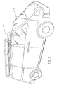
- figure 1 is a perspective view of a delivery van on which a roof-rack according to the invention is placed;
- figure 2 is a perspective view of a roof-rack according to the invention wherein the structures extending in longitudinal direction are separated from the elements extending in transverse direction; and
- figure 3 is an exploded view of a detail of the roof-rack construction according to the invention.
-
- As is apparent from figure 1, a roof-
rack 1 is placed on a delivery van 2. As shown in figure 2, roof-rack 1 is formed by two longitudinally extendingstructures 3 which are connected by transversely extendingtransverse elements 4. In the embodiment shown in figure 2,supports 5 are arranged on threetransverse elements 4 for fastening the roof-rack on the roof of delivery van (2). - In order to facilitate placing of long objects, such as ladders, on the roof-rack, there is arranged on the rear side of the roof-rack a roller 6 which is mounted in two
end parts 7 forming part of the longitudinally extendingstructure 3. - The construction will now be further elucidated with reference to figure 3.
- Figure 3 shows that the
structure 3 extending in longitudinal direction is formed by two longitudinally extendingprofiles 8, which are mutually identical and which are placed with their flat side toward each other. - Arranged on the relevant flat side of the aluminium profile is a slot 9 which leads to a
cavity 10. Bothaluminium profiles 8 are connected byvertical profiles 11 so as to provide sufficient strength. -
Profile parts 11 are fastened by means ofanchors 12.Anchors 12 are each formed by apin 13 to which ahead 14 is attached, and wherein asquare 15 is placed betweenhead 14 andpin 13, thereby preventing rotation of the anchor. Aconical notch 16 is made in the pin. - A
channel 17 is arranged inprofile 11 to guidepin 13. After shortening the piece ofaluminium profile 11, ahole 18 is drilled at a distance from both ends of the profile, in which hole is pushed asleeve 19. Likeanchor 12,sleeve 19 is preferably manufactured from stainless steel. Insleeve 19 is arranged anopening 20, the diameter of which is slightly larger than that ofpin 13. - During assembly the
profile part 11 with thesleeves 19 placed therein is placed ontoprofile 8, wherein ananchor 12 has been placed beforehand incavity 10 ofprofile 8. Thepin 13 ofanchor 12 will herein extend intochannel 17 and through opening 20.Cavity 16 is herein visible from the interior ofsleeve 19. Fixation then takes place by screwing aheadless screw 21 intosleeve 19. Ascrew thread 22 is arranged for this purpose in the interior of the sleeve. Theheadless screw 21 is provided on its front side with atip 23. As theheadless screw 21 is screwed in, thetip 23 thereof will herein move intoconical opening 16. The dimensioning of the components is herein such that, asscrew 21 is tightened, thetip 23 thereof pullsanchor 12 towardsleeve 19. A firm clamp connection is herein obtained betweenprofile part 11 andprofile 8.Upper profile 8 is of course fastened in the same manner to the parts ofvertical profile 11. - A sturdy construction is hereby obtained. It is essential here that it is possible to displace the
profile parts 11 in longitudinal direction by loosening theheadless screws 21. Fixation can be obtained by then re-tightening. - For finishing of the ends of the
profiles 8 placed one above another use is made ofplastic end pieces 24. The plastic end pieces are constructed symmetrically, so that they can be used at both the front and rear and on both left and right of the roof-rack. For fixing inprofile parts 8 each of the end pieces is provided with twotongues 25 which are dimensioned to extend intocavities 10 ofprofiles 8.Recesses 26 are arranged intongues 25. Intorecesses 26 can be placedmetal pressure pieces 27 which are provided with ahole 28 in which screw thread is arranged. - Fastening then takes place by screwing
headless screws 21 throughholes 29 arranged in the tongues, which screws engage in the screw thread of opening 28. When the end pieces are subsequently pushed with theirtongues 25 intocavity 10, it is possible by means of an Allen key to tighten theheadless screws 21 via slot 9, whereby the tip ofheadless screws 21 locks against the underside respectively the upper side ofchannel 10, andpressure piece 27 clamps thetongue 25. - As already stated, it is possible to mount a roller 6 on
end pieces 24. Use can be made for this purpose of a drill marking arranged inend piece 24. - For the purpose of fastening the
transverse elements 4 tolower profiles 8, use is made of the same fastening as for fasteningvertical profiles 11 toprofiles 8.Profiles 8 are provided for this purpose with alateral slot 30 and alateral cavity 31. It is herein noted thatprofile 8, with the exception oflateral slot 30, is symmetrical;lateral slot 30 is arranged for the option of fastening the transverse elements. It is also pointed out thattransverse elements 4 are formed by the same profile asvertical profile parts 11; this also results in further rationalization. - It is finally noted that it is possible to assemble such a roof-rack with simple means. All that is necessary for this purpose are an open-end spanner and an Allen key. This provides the option of supplying the roof-rack as a construction kit.
- Owing to the fact that use is made of aluminium profiles, it is possible to adjust the dimensions of the roof-rack by shortening the profiles. By including in a construction kit profiles which are suitable for making a large roof-rack, it is possible for the construction kit to be made to size during assembly by sawing profiles. This results in a further universality of use.
Claims (14)
- Roof-rack for a motor vehicle, comprising:characterized in that the fastening elements are fastened releasably to the structures.two structures extending in longitudinal direction,a number of transverse elements which extend between the structures and which are connected to the structures by means of fastening elements, andsupports connected to the structures or the transverse elements for fixing the roof-rack on the motor vehicle,
- Roof-rack as claimed in claim 1, characterized in that the fastening elements can be carried from a fixation position, in which they are fixedly connected to the structures, into a sliding position in which they are movable along the structures.
- Roof-rack as claimed in claim 2, characterized in that the structures comprise a profile extending in longitudinal direction, and that the fastening elements extend into the profile and can be fixed in a random position on the profile.
- Roof-rack as claimed in claim 3, characterized in that the fastening elements each comprise an anchor which extends into the profile, and that the fastening elements each comprise a tensioning element which is connected to the relevant transverse element and which is adapted for pulling the anchor towards it.
- Roof-rack as claimed in claim 4, characterized in that the transverse elements are hollow, that the tensioning element is situated in the transverse elements, and that the tensioning elements comprise a control element which can be operated from outside the transverse element and which, when operated, pulls the anchor towards the fastening element.
- Roof-rack as claimed in claim 5, characterized in that the tensioning elements comprise a sleeve which can be placed into an opening arranged in the transverse element, and that the control element comprises a bolt which is displaceable in the sleeve by means of screw thread and which is coupled mechanically to the anchor such that the anchor is pulled towards the bolt when the bolt is tightened.
- Roof-rack as claimed in claim 6, characterized in that the bolt is provided with a conical end and that the anchor is provided with an at least partly oblique surface which is in contact with the conical part of the bolt.
- Roof-rack as claimed in any of the claims 4-7, characterized in that a guide is arranged in the transverse elements for guiding a part of the anchor.
- Roof-rack as claimed in claim 8, characterized in that the transverse elements are formed by an extruded aluminium profile.
- Roof-rack as claimed in any of the foregoing claims, characterized in that the structures each comprise two identical profiles extending in longitudinal direction which are mutually connected by substantially vertically extending rods.
- Roof-rack as claimed in claim 10, characterized in that the vertical rods are formed by the same aluminium profiles as the transverse elements, and that the vertical rods are connected to the longitudinally extending profiles in the same manner as the transverse profiles.
- Roof-rack as claimed in claim 10 or 11, characterized in that the profiles extending one above another in longitudinal direction are mutually connected at their front and rear ends by identical end pieces.
- Roof-rack as claimed in claim 12, characterized in that the end pieces are manufactured from plastic and that they are connected to the profiles extending in longitudinal direction by a clamping screw connection.
- Kit of parts for assembling a roof-rack as claimed in any of the foregoing claims.
Applications Claiming Priority (2)
| Application Number | Priority Date | Filing Date | Title |
|---|---|---|---|
| NL1016468 | 2000-10-24 | ||
| NL1016468 | 2000-10-24 |
Publications (2)
| Publication Number | Publication Date |
|---|---|
| EP1205357A2 true EP1205357A2 (en) | 2002-05-15 |
| EP1205357A3 EP1205357A3 (en) | 2004-08-04 |
Family
ID=19772297
Family Applications (1)
| Application Number | Title | Priority Date | Filing Date |
|---|---|---|---|
| EP01204036A Withdrawn EP1205357A3 (en) | 2000-10-24 | 2001-10-24 | Roofrack constituted from modular elements |
Country Status (1)
| Country | Link |
|---|---|
| EP (1) | EP1205357A3 (en) |
Cited By (6)
| Publication number | Priority date | Publication date | Assignee | Title |
|---|---|---|---|---|
| DE10260280A1 (en) * | 2002-12-20 | 2004-07-15 | Susanne Frensch | Roof rack fitted onto car for carrying luggage has four horizontal crossbars supporting ends of horizontal slats and fitted with downwardly-extending legs with fastening clamps |
| WO2009126286A1 (en) | 2008-04-11 | 2009-10-15 | Levi Avraham Y | Roof rack for automotive vehicles |
| EP3368377A4 (en) * | 2015-10-27 | 2019-03-13 | Horizon Global Corporation | LOAD SUPPORT SYSTEM FOR VEHICLE ROOF |
| RU2698602C2 (en) * | 2017-11-16 | 2019-08-28 | Общество с ограниченной ответственностью "ПАРУС и К" | Method for assembling a car trunk basket |
| CN111409562A (en) * | 2020-04-15 | 2020-07-14 | 北京汽车集团越野车有限公司 | Car roof luggage rack structure |
| FR3120588A1 (en) * | 2021-03-15 | 2022-09-16 | Joubert Productions | ASSEMBLY KIT FOR VEHICLE ROOF RACK AND ASSOCIATED METHOD |
Citations (1)
| Publication number | Priority date | Publication date | Assignee | Title |
|---|---|---|---|---|
| NL6803800A (en) | 1967-03-21 | 1968-09-23 |
Family Cites Families (3)
| Publication number | Priority date | Publication date | Assignee | Title |
|---|---|---|---|---|
| DE69430544T2 (en) * | 1993-07-07 | 2002-12-05 | Smc K.K., Tokio/Tokyo | CONNECTING MECHANISM FOR STRUCTURAL ELEMENTS |
| GB2314059B (en) * | 1996-06-12 | 2000-09-06 | Jac Products Inc | Load bar for automobile luggage carrier |
| CA2232829A1 (en) * | 1998-03-23 | 1999-09-23 | Michael Moliner | Attachment mechanisms for securing utility racks to vehicles |
-
2001
- 2001-10-24 EP EP01204036A patent/EP1205357A3/en not_active Withdrawn
Patent Citations (1)
| Publication number | Priority date | Publication date | Assignee | Title |
|---|---|---|---|---|
| NL6803800A (en) | 1967-03-21 | 1968-09-23 |
Cited By (8)
| Publication number | Priority date | Publication date | Assignee | Title |
|---|---|---|---|---|
| DE10260280A1 (en) * | 2002-12-20 | 2004-07-15 | Susanne Frensch | Roof rack fitted onto car for carrying luggage has four horizontal crossbars supporting ends of horizontal slats and fitted with downwardly-extending legs with fastening clamps |
| WO2009126286A1 (en) | 2008-04-11 | 2009-10-15 | Levi Avraham Y | Roof rack for automotive vehicles |
| EP2271515A4 (en) * | 2008-04-11 | 2012-04-04 | Avraham Y Levi | Roof rack for automotive vehicles |
| EP3368377A4 (en) * | 2015-10-27 | 2019-03-13 | Horizon Global Corporation | LOAD SUPPORT SYSTEM FOR VEHICLE ROOF |
| RU2698602C2 (en) * | 2017-11-16 | 2019-08-28 | Общество с ограниченной ответственностью "ПАРУС и К" | Method for assembling a car trunk basket |
| CN111409562A (en) * | 2020-04-15 | 2020-07-14 | 北京汽车集团越野车有限公司 | Car roof luggage rack structure |
| FR3120588A1 (en) * | 2021-03-15 | 2022-09-16 | Joubert Productions | ASSEMBLY KIT FOR VEHICLE ROOF RACK AND ASSOCIATED METHOD |
| EP4059777A1 (en) * | 2021-03-15 | 2022-09-21 | Joubert Productions | Assembly kit for gallery for the roof of a vehicle and associated method |
Also Published As
| Publication number | Publication date |
|---|---|
| EP1205357A3 (en) | 2004-08-04 |
Similar Documents
| Publication | Publication Date | Title |
|---|---|---|
| US5464140A (en) | Mounting structure for roof rack support members | |
| FI82757C (en) | Device for mounting a rail or the like on a surface | |
| EP0785320A1 (en) | Screw fastener | |
| US6276651B1 (en) | Mounting device for flagpoles | |
| US7722115B2 (en) | Method and apparatus for bicycle seat adjustment | |
| US20100040312A1 (en) | Guide rail of a linear guide | |
| US4801119A (en) | Awning support for recreational vehicles | |
| US20100037552A1 (en) | Side mounted drill bolt and threaded anchor system for veneer wall tie connection | |
| US12114773B2 (en) | Hardware bar assembly | |
| HRP940782A2 (en) | Clamping device for detachably joining two profiles | |
| GB2360543A (en) | Telescopic tube clamping arrangement | |
| US4606432A (en) | Adjustable ladder leg | |
| EP1205357A2 (en) | Roofrack constituted from modular elements | |
| US20110309119A1 (en) | Device for attaching accessories to bars, application to motor vehicle roof rail bars | |
| US20190270354A1 (en) | Trailer coupling having a support element | |
| US5839867A (en) | Wall support at a mounting frame | |
| US20040144589A1 (en) | Mount frame for an electric motor-driven wheeled vehicle | |
| DE19731407C1 (en) | Fastening for door-handle on profiled aluminium@ frame | |
| US4981276A (en) | Support for towels and the like | |
| HU213696B (en) | Device for joining accessories to switchboards | |
| US20010012472A1 (en) | Connector device | |
| US6625850B2 (en) | V-lock | |
| EP3608551A1 (en) | Clamping anchor for fastening ironwork to a hollow profile of a window or door | |
| US12117039B2 (en) | Connector and system for interconnecting tubular profiles | |
| DE102006010447B4 (en) | Multifunctional kit for mounting storage devices |
Legal Events
| Date | Code | Title | Description |
|---|---|---|---|
| PUAI | Public reference made under article 153(3) epc to a published international application that has entered the european phase |
Free format text: ORIGINAL CODE: 0009012 |
|
| AK | Designated contracting states |
Kind code of ref document: A2 Designated state(s): AT BE CH CY DE DK ES FI FR GB GR IE IT LI LU MC NL PT SE TR |
|
| AX | Request for extension of the european patent |
Free format text: AL;LT;LV;MK;RO;SI |
|
| PUAL | Search report despatched |
Free format text: ORIGINAL CODE: 0009013 |
|
| AK | Designated contracting states |
Kind code of ref document: A3 Designated state(s): AT BE CH CY DE DK ES FI FR GB GR IE IT LI LU MC NL PT SE TR |
|
| AX | Request for extension of the european patent |
Extension state: AL LT LV MK RO SI |
|
| AKX | Designation fees paid | ||
| REG | Reference to a national code |
Ref country code: DE Ref legal event code: 8566 |
|
| STAA | Information on the status of an ep patent application or granted ep patent |
Free format text: STATUS: THE APPLICATION IS DEEMED TO BE WITHDRAWN |
|
| 18D | Application deemed to be withdrawn |
Effective date: 20050205 |