EP1205333A2 - In-tank fuel line quick connector - Google Patents
In-tank fuel line quick connector Download PDFInfo
- Publication number
- EP1205333A2 EP1205333A2 EP01203915A EP01203915A EP1205333A2 EP 1205333 A2 EP1205333 A2 EP 1205333A2 EP 01203915 A EP01203915 A EP 01203915A EP 01203915 A EP01203915 A EP 01203915A EP 1205333 A2 EP1205333 A2 EP 1205333A2
- Authority
- EP
- European Patent Office
- Prior art keywords
- tank
- quick connector
- connector assembly
- fuel line
- line quick
- Prior art date
- Legal status (The legal status is an assumption and is not a legal conclusion. Google has not performed a legal analysis and makes no representation as to the accuracy of the status listed.)
- Granted
Links
Images


Classifications
-
- F—MECHANICAL ENGINEERING; LIGHTING; HEATING; WEAPONS; BLASTING
- F02—COMBUSTION ENGINES; HOT-GAS OR COMBUSTION-PRODUCT ENGINE PLANTS
- F02M—SUPPLYING COMBUSTION ENGINES IN GENERAL WITH COMBUSTIBLE MIXTURES OR CONSTITUENTS THEREOF
- F02M37/00—Apparatus or systems for feeding liquid fuel from storage containers to carburettors or fuel-injection apparatus; Arrangements for purifying liquid fuel specially adapted for, or arranged on, internal-combustion engines
- F02M37/0011—Constructional details; Manufacturing or assembly of elements of fuel systems; Materials therefor
- F02M37/0017—Constructional details; Manufacturing or assembly of elements of fuel systems; Materials therefor related to fuel pipes or their connections, e.g. joints or sealings
-
- B—PERFORMING OPERATIONS; TRANSPORTING
- B60—VEHICLES IN GENERAL
- B60K—ARRANGEMENT OR MOUNTING OF PROPULSION UNITS OR OF TRANSMISSIONS IN VEHICLES; ARRANGEMENT OR MOUNTING OF PLURAL DIVERSE PRIME-MOVERS IN VEHICLES; AUXILIARY DRIVES FOR VEHICLES; INSTRUMENTATION OR DASHBOARDS FOR VEHICLES; ARRANGEMENTS IN CONNECTION WITH COOLING, AIR INTAKE, GAS EXHAUST OR FUEL SUPPLY OF PROPULSION UNITS IN VEHICLES
- B60K15/00—Arrangement in connection with fuel supply of combustion engines or other fuel consuming energy converters, e.g. fuel cells; Mounting or construction of fuel tanks
-
- F—MECHANICAL ENGINEERING; LIGHTING; HEATING; WEAPONS; BLASTING
- F02—COMBUSTION ENGINES; HOT-GAS OR COMBUSTION-PRODUCT ENGINE PLANTS
- F02M—SUPPLYING COMBUSTION ENGINES IN GENERAL WITH COMBUSTIBLE MIXTURES OR CONSTITUENTS THEREOF
- F02M37/00—Apparatus or systems for feeding liquid fuel from storage containers to carburettors or fuel-injection apparatus; Arrangements for purifying liquid fuel specially adapted for, or arranged on, internal-combustion engines
- F02M37/0076—Details of the fuel feeding system related to the fuel tank
- F02M37/0082—Devices inside the fuel tank other than fuel pumps or filters
-
- F—MECHANICAL ENGINEERING; LIGHTING; HEATING; WEAPONS; BLASTING
- F02—COMBUSTION ENGINES; HOT-GAS OR COMBUSTION-PRODUCT ENGINE PLANTS
- F02M—SUPPLYING COMBUSTION ENGINES IN GENERAL WITH COMBUSTIBLE MIXTURES OR CONSTITUENTS THEREOF
- F02M37/00—Apparatus or systems for feeding liquid fuel from storage containers to carburettors or fuel-injection apparatus; Arrangements for purifying liquid fuel specially adapted for, or arranged on, internal-combustion engines
- F02M37/04—Feeding by means of driven pumps
- F02M37/08—Feeding by means of driven pumps electrically driven
- F02M37/10—Feeding by means of driven pumps electrically driven submerged in fuel, e.g. in reservoir
- F02M37/106—Feeding by means of driven pumps electrically driven submerged in fuel, e.g. in reservoir the pump being installed in a sub-tank
-
- F—MECHANICAL ENGINEERING; LIGHTING; HEATING; WEAPONS; BLASTING
- F16—ENGINEERING ELEMENTS AND UNITS; GENERAL MEASURES FOR PRODUCING AND MAINTAINING EFFECTIVE FUNCTIONING OF MACHINES OR INSTALLATIONS; THERMAL INSULATION IN GENERAL
- F16L—PIPES; JOINTS OR FITTINGS FOR PIPES; SUPPORTS FOR PIPES, CABLES OR PROTECTIVE TUBING; MEANS FOR THERMAL INSULATION IN GENERAL
- F16L37/00—Couplings of the quick-acting type
- F16L37/08—Couplings of the quick-acting type in which the connection between abutting or axially overlapping ends is maintained by locking members
- F16L37/084—Couplings of the quick-acting type in which the connection between abutting or axially overlapping ends is maintained by locking members combined with automatic locking
- F16L37/098—Couplings of the quick-acting type in which the connection between abutting or axially overlapping ends is maintained by locking members combined with automatic locking by means of flexible hooks
- F16L37/0985—Couplings of the quick-acting type in which the connection between abutting or axially overlapping ends is maintained by locking members combined with automatic locking by means of flexible hooks the flexible hook extending radially inwardly from an outer part and engaging a bead, recess or the like on an inner part
- F16L37/0987—Couplings of the quick-acting type in which the connection between abutting or axially overlapping ends is maintained by locking members combined with automatic locking by means of flexible hooks the flexible hook extending radially inwardly from an outer part and engaging a bead, recess or the like on an inner part the flexible hook being progressively compressed by axial tensile loads acting on the coupling
-
- B—PERFORMING OPERATIONS; TRANSPORTING
- B60—VEHICLES IN GENERAL
- B60K—ARRANGEMENT OR MOUNTING OF PROPULSION UNITS OR OF TRANSMISSIONS IN VEHICLES; ARRANGEMENT OR MOUNTING OF PLURAL DIVERSE PRIME-MOVERS IN VEHICLES; AUXILIARY DRIVES FOR VEHICLES; INSTRUMENTATION OR DASHBOARDS FOR VEHICLES; ARRANGEMENTS IN CONNECTION WITH COOLING, AIR INTAKE, GAS EXHAUST OR FUEL SUPPLY OF PROPULSION UNITS IN VEHICLES
- B60K15/00—Arrangement in connection with fuel supply of combustion engines or other fuel consuming energy converters, e.g. fuel cells; Mounting or construction of fuel tanks
- B60K15/03—Fuel tanks
- B60K2015/03328—Arrangements or special measures related to fuel tanks or fuel handling
- B60K2015/03453—Arrangements or special measures related to fuel tanks or fuel handling for fixing or mounting parts of the fuel tank together
Definitions
- the present invention relates generally to fuel tanks for vehicles and, more particularly, to an in-tank fuel line quick connector assembly for a fuel tank of a vehicle.
- the fuel tank includes a fuel pump module disposed therein with a removable cover sealed to the top of the fuel tank having an electrical connector and a fuel line outlet connector.
- the fuel pump module includes a fuel reservoir and an electrical fuel pump disposed in the reservoir.
- Quick connect fittings have been used in fuel systems to make connections external to the fuel tank. Inside the fuel tank, hydraulic connections have been made using hoses and clamps or by press fitting polymer tubes onto various end-forms, the most common one referred to a as a "fir tree" connection. As more and more components of the fuel tank such as regulators, filters, and valves are installed inside the fuel tank in order to meet tighter emission standards, there is a need to use quick connect fittings to make (hydraulic) liquid connections without the use of tooling.
- Quick connect fittings used outside of the fuel tank have specific performance requirements which include that the connection be leak free under all conditions and temperatures.
- the quick connect fitting must prevent separation of a connection between the connector and the tubing to which it is assembled. Because of these requirements, the connector is longer than what it needs to be for the inside of the fuel tank. For example, the space required by O-rings and glands as well as the need for barbs to ensure the retention of the quick connect fitting to polymer tubes create an undesirable length. Further, additional space is needed to allow a release tool to be inserted. Inside the fuel tank, space (length) is at a premium, and the smaller a component can be made, the easier it is to work into the design.
- a new quick connector to be used inside of a fuel tank for a vehicle. It is also desirable to provide an in-tank fuel line quick connector for a fuel tank in a vehicle that has a smaller size. It is further desirable to provide an in-tank fuel line quick connector for a fuel tank in a vehicle that reduces the number of parts and cost.
- the present invention is an in-tank fuel line quick connector assembly for a fuel tank in a vehicle including a first member adapted to be disposed inside of the fuel tank and having a first projection extending outwardly.
- the in-tank fuel line quick connector assembly also includes a second member adapted to be disposed inside of the fuel tank and having a cavity to receive the first projection.
- the in-tank fuel line quick connector assembly further includes a seal ring disposed in the cavity to engage the first member.
- the second member has opposed latches adjacent the cavity and are movable to engage the projection for retaining the first member and the second member together.
- an in-tank fuel line quick connector assembly is provided for inside of a fuel tank of a vehicle.
- the in-tank fuel line quick connector assembly reduces the size of the package and space needed for the insertion of a removal tool to meet space constraints inside of the fuel tank.
- the in-tank fuel line quick connector assembly reduces the number of components needed to seal the connection and the insertion force of the male to female quick connect fittings.
- the in-tank fuel line quick connector assembly simplifies the assembly process as it can be installed by hand.
- an in-tank fuel line quick connector assembly 10 for a fuel tank, generally indicated at 12, in a vehicle (not shown).
- the fuel tank 12 is of a generally rectangular type.
- the fuel tank 12 has a bottom wall 14.
- the fuel tank 12 also has a side wall 16 around a periphery of the bottom wall 14 and extending generally perpendicular thereto.
- the fuel tank 12 has a top wall 18 around a periphery of the side wall 16 and extending generally perpendicular thereto.
- the top wall 18 includes at least one opening 20 therein.
- the fuel tank 12 includes a fuel pump module 22 disposed therein with a removable fuel tank cover 24 disposed in the opening 20 and sealed to the top wall 18 of the fuel tank 12.
- the fuel tank cover 24 has an electrical connector (not shown) and a fuel line outlet connector 26 extending therethrough.
- the fuel pump module 22 also includes a return fuel member 28 extending upwardly.
- the return fuel member 28 is tubular and has a generally circular cross-sectional shape.
- the return fuel member 28 has a passageway (not shown) extending axially therethrough.
- the return fuel. member 28 is integral and formed as one-piece with the fuel pump module 22. It should be appreciated that, except for the in-tank fuel line quick connector assembly 10, the fuel tank 12 is conventional and known in the art.
- the in-tank fuel line quick connector assembly 10 includes a male fitting or first member 30 having a tubular configuration.
- the first member 30 has an exterior surface 32 with an annular projection or retaining bead 34 extending radially outwardly therefrom and spaced from one end thereof.
- the first member 30 also has a locking bead 36 extending radially and spaced axially between the retaining bead 34 and the end thereof.
- the locking bead 36 extends radially a distance greater than the retaining bead 34.
- the first member 30 further has a reduced diameter end 38 extending axially from the retaining bead 34.
- the first member 30 also has a passageway 39 extending axially therethrough.
- the first member 30 is made of a rigid material such as a plastic material and has a predetermined diameter and wall thickness. It should be appreciated that the first member 30 may be made of any suitable material, diameter, and wall thickness. It should also be appreciated that a hose 39a interconnects the end of the first member 30 and the fuel line outlet connector 26.
- the in-tank fuel line quick connector assembly 10 also includes a female fitting or second member 40 for connection to the first member 30.
- the second member 40 has a housing or body 42 extending axially.
- the body 42 is generally cylindrical and has a connector portion 43 extending axially with a plurality of barbs 44 at one end.
- the barbs 44 extend radially and are annular and spaced axially for insertion into the return fuel member 28 of the fuel pump module 22.
- the second member 40 is made of a fuel resistant polymer material such as POM (Acetal) that is unfilled or filled with a low percentage of glass or carbon fiber. It should be appreciated that the polymer material has material properties such that it can be used in snap fit designs.
- the second member 40 includes a cavity 46 extending axially therein at the other end.
- the cavity 46 has an inner surface 48 and receives the reduced diameter end 38 and retaining bead 34 of the first member 30.
- the second member 40 also has a passageway 50 extending axially through the body 42 to the other end thereof and communicates with the cavity 46.
- the second member 40 has a pair of opposed flex arms or latches 52 on the body 42 and located radially adjacent the cavity 46.
- the flex arms 52 have a first edge 54 and a second edge 56 axially spaced from the first edge 54.
- the first edge 54 is molded as integral part of the body 42.
- the body 42 includes an aperture 58 extending radially therethrough around the sides and second edge 56 of the flex arms 52 to allow the flex arms 52 to flex via the first edge 54. It should be appreciated that the flex arms 52 extend into the apertures 58 from the first edge 54 and are integral with the body 42 retain the first member 30 when pressed into it.
- the in-tank fuel line quick connector assembly 10 also includes a seal 60 disposed in the cavity 46 for engaging the first member 30 and providing sealing between the body 42 and the first member 30.
- the seal 60 is made of an elastomeric material.
- the seal 60 is annular.
- the seal 60 has a generally circular cross-section.
- the seal 60 is disposed about the reduced diameter end 38 of the first member 30 and sandwiched between the retaining bead 34 and a shoulder 62 of the body 42 extending into the cavity 46. It should be appreciated that the seal 60 resists leakage of fluid between the first member 30 and second member 40.
- the in-tank fuel line quick connector assembly 10 is shown assembled in a connect position.
- the seal 60 is disposed in the cavity 46.
- the first member 30 engages the seal 60 and is disposed in the cavity 46 of second member 40 and about the first member 30.
- the connection between the body 42 and the first member 30 is made when during insertion, the locking bead 36 on the first member 30 flexes the flex arms 52 outward and the second edge 56 of each flex arm 52 drops down on the backside of the locking bead 36.
- a tool such as a sleeve (not shown) is moved axially by an operator toward the second member 40.
- the axial end of the sleeve engages the flex arms 52.
- the flex arms 52 are expanded to a release position.
- the first member 30 is then moved axially by an operator away from the second member 40 to remove the first member 30 from the cavity 46 of the second member 40. It should be appreciated that once the first member 30 is removed, the flex arms 52 return to their original position.
- FIG 4 another embodiment, according to the present invention, of the body 42 of the in-tank fuel line quick connector assembly 10 is shown.
- the body 142 has only two barbs 144 on the connector portion 143 onto which the interface of either a flexible tubing (not shown) or fuel return member 30 is pressed onto to save space.
- the application of this connector assembly 10 is intended specifically for the inside of the fuel tank 12 where no forces other than the force created by the hydraulic pressure acting on the inside of the tubing can pull the tubing and the body 142 apart.
- one of the retaining latches or flex arms 152 is illustrated on the body 142.
- the second edge 156 of the flex arm 152 is the edge, which in combination with the locking bead 36 provides the retention of the first member 30 and second member 40.
- the second edge 156 has a slot 190 that allows for the insertion of a tool (not shown) such as pins of a snap ring pair of pliers.
- a tool such as pins of a snap ring pair of pliers.
- the body 242 has the connector portion 243 with the barbs 244 at an angle such as forty-five or ninety degrees to the remainder of the body 242. As illustrated, the connector portion 243 is at an angle of ninety degrees relative to the remainder of the body 242. It should be appreciated that the smaller package size of this design is accomplished by reducing the number of barbs 244 at the tube to body interface, by reducing the number of o-rings from two to one, and by eliminating the need to provide insertion room for a removal tool.
Abstract
Description
- The present invention claims the priority date of copending United States Provisional Patent
Application Serial Number 60/246,874, filed November 8, 2000. - The present invention relates generally to fuel tanks for vehicles and, more particularly, to an in-tank fuel line quick connector assembly for a fuel tank of a vehicle.
- It is known to provide a fuel tank for a vehicle to hold fuel to be used by an engine of the vehicle. In some vehicles, the fuel tank includes a fuel pump module disposed therein with a removable cover sealed to the top of the fuel tank having an electrical connector and a fuel line outlet connector. The fuel pump module includes a fuel reservoir and an electrical fuel pump disposed in the reservoir.
- Quick connect fittings have been used in fuel systems to make connections external to the fuel tank. Inside the fuel tank, hydraulic connections have been made using hoses and clamps or by press fitting polymer tubes onto various end-forms, the most common one referred to a as a "fir tree" connection. As more and more components of the fuel tank such as regulators, filters, and valves are installed inside the fuel tank in order to meet tighter emission standards, there is a need to use quick connect fittings to make (hydraulic) liquid connections without the use of tooling.
- Quick connect fittings used outside of the fuel tank have specific performance requirements which include that the connection be leak free under all conditions and temperatures. The quick connect fitting must prevent separation of a connection between the connector and the tubing to which it is assembled. Because of these requirements, the connector is longer than what it needs to be for the inside of the fuel tank. For example, the space required by O-rings and glands as well as the need for barbs to ensure the retention of the quick connect fitting to polymer tubes create an undesirable length. Further, additional space is needed to allow a release tool to be inserted. Inside the fuel tank, space (length) is at a premium, and the smaller a component can be made, the easier it is to work into the design.
- Therefore, it is desirable to provide a new quick connector to be used inside of a fuel tank for a vehicle. It is also desirable to provide an in-tank fuel line quick connector for a fuel tank in a vehicle that has a smaller size. It is further desirable to provide an in-tank fuel line quick connector for a fuel tank in a vehicle that reduces the number of parts and cost.
- It is, therefore, one object of the present invention to provide a new quick connector assembly for inside of a fuel tank in a vehicle.
- It is another object of the present invention to provide an in-tank fuel line quick connector assembly for a fuel tank in a vehicle.
- To achieve the foregoing objects, the present invention is an in-tank fuel line quick connector assembly for a fuel tank in a vehicle including a first member adapted to be disposed inside of the fuel tank and having a first projection extending outwardly. The in-tank fuel line quick connector assembly also includes a second member adapted to be disposed inside of the fuel tank and having a cavity to receive the first projection. The in-tank fuel line quick connector assembly further includes a seal ring disposed in the cavity to engage the first member. The second member has opposed latches adjacent the cavity and are movable to engage the projection for retaining the first member and the second member together.
- One advantage of the present invention is that an in-tank fuel line quick connector assembly is provided for inside of a fuel tank of a vehicle. Another advantage of the present invention is that the in-tank fuel line quick connector assembly reduces the size of the package and space needed for the insertion of a removal tool to meet space constraints inside of the fuel tank. Yet another advantage of the present invention is that the in-tank fuel line quick connector assembly reduces the number of components needed to seal the connection and the insertion force of the male to female quick connect fittings. Still another advantage of the present invention is that the in-tank fuel line quick connector assembly simplifies the assembly process as it can be installed by hand. A further advantage of the present invention is that the in-tank fuel line quick connector assembly reduces cost because it can be assembled by an operator without the use of a mechanical assist and the function is accomplished with the addition of one molded part and an o-ring. Yet a further advantage of the present invention is that the in-tank fuel line quick connector assembly has added value because it allows for serviceability of the components within the fuel module.
- Other objects, features, and advantages of the present invention will be readily appreciated, as the same becomes better understood, after reading the subsequent description taken in conjunction with the accompanying drawings.
-
- Figure 1 is a fragmentary elevational view of an in-tank fuel line quick connector assembly, according to the present invention, illustrated in operational relationship with a fuel tank of a vehicle.
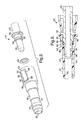
- Figure 2 is an enlarged exploded perspective view of the in-tank fuel line quick connector assembly of Figure 1.
- Figure 3 is a fragmentary elevational view of the in-tank fuel line quick connector assembly of Figure 1.
- Figure 4 is a perspective view of another embodiment, according to the present invention, of the in-tank fuel line quick connector assembly of Figure 1.
- Figure 5 is an enlarged perspective view of a portion of the in-tank fuel line quick connector assembly of Figure 4.
- Figure 6 is a perspective view of yet another embodiment, according to the present invention, of the intank fuel line quick connector assembly of Figure 1.
-
- Referring to the drawings and in particular Figure 1, one embodiment of an in-tank fuel line
quick connector assembly 10, according to the present invention, is shown for a fuel tank, generally indicated at 12, in a vehicle (not shown). In this embodiment, thefuel tank 12 is of a generally rectangular type. Thefuel tank 12 has abottom wall 14. Thefuel tank 12 also has aside wall 16 around a periphery of thebottom wall 14 and extending generally perpendicular thereto. Thefuel tank 12 has atop wall 18 around a periphery of theside wall 16 and extending generally perpendicular thereto. Thetop wall 18 includes at least one opening 20 therein. Thefuel tank 12 includes afuel pump module 22 disposed therein with a removablefuel tank cover 24 disposed in the opening 20 and sealed to thetop wall 18 of thefuel tank 12. Thefuel tank cover 24 has an electrical connector (not shown) and a fuelline outlet connector 26 extending therethrough. Thefuel pump module 22 also includes areturn fuel member 28 extending upwardly. Thereturn fuel member 28 is tubular and has a generally circular cross-sectional shape. Thereturn fuel member 28 has a passageway (not shown) extending axially therethrough. The return fuel.member 28 is integral and formed as one-piece with thefuel pump module 22. It should be appreciated that, except for the in-tank fuel linequick connector assembly 10, thefuel tank 12 is conventional and known in the art. - The in-tank fuel line
quick connector assembly 10 includes a male fitting orfirst member 30 having a tubular configuration. Thefirst member 30 has anexterior surface 32 with an annular projection or retainingbead 34 extending radially outwardly therefrom and spaced from one end thereof. Thefirst member 30 also has alocking bead 36 extending radially and spaced axially between theretaining bead 34 and the end thereof. Thelocking bead 36 extends radially a distance greater than theretaining bead 34. Thefirst member 30 further has a reduceddiameter end 38 extending axially from theretaining bead 34. Thefirst member 30 also has apassageway 39 extending axially therethrough. Thefirst member 30 is made of a rigid material such as a plastic material and has a predetermined diameter and wall thickness. It should be appreciated that thefirst member 30 may be made of any suitable material, diameter, and wall thickness. It should also be appreciated that a hose 39a interconnects the end of thefirst member 30 and the fuelline outlet connector 26. - The in-tank fuel line
quick connector assembly 10 also includes a female fitting orsecond member 40 for connection to thefirst member 30. Thesecond member 40 has a housing orbody 42 extending axially. Thebody 42 is generally cylindrical and has aconnector portion 43 extending axially with a plurality ofbarbs 44 at one end. Thebarbs 44 extend radially and are annular and spaced axially for insertion into thereturn fuel member 28 of thefuel pump module 22. Preferably, thesecond member 40 is made of a fuel resistant polymer material such as POM (Acetal) that is unfilled or filled with a low percentage of glass or carbon fiber. It should be appreciated that the polymer material has material properties such that it can be used in snap fit designs. - The
second member 40 includes acavity 46 extending axially therein at the other end. Thecavity 46 has an inner surface 48 and receives the reduceddiameter end 38 and retainingbead 34 of thefirst member 30. Thesecond member 40 also has apassageway 50 extending axially through thebody 42 to the other end thereof and communicates with thecavity 46. Thesecond member 40 has a pair of opposed flex arms or latches 52 on thebody 42 and located radially adjacent thecavity 46. Theflex arms 52 have afirst edge 54 and asecond edge 56 axially spaced from thefirst edge 54. Thefirst edge 54 is molded as integral part of thebody 42. Thebody 42 includes anaperture 58 extending radially therethrough around the sides andsecond edge 56 of theflex arms 52 to allow theflex arms 52 to flex via thefirst edge 54. It should be appreciated that theflex arms 52 extend into theapertures 58 from thefirst edge 54 and are integral with thebody 42 retain thefirst member 30 when pressed into it. - The in-tank fuel line
quick connector assembly 10 also includes aseal 60 disposed in thecavity 46 for engaging thefirst member 30 and providing sealing between thebody 42 and thefirst member 30. Preferably, theseal 60 is made of an elastomeric material. Theseal 60 is annular. Theseal 60 has a generally circular cross-section. Theseal 60 is disposed about the reduced diameter end 38 of thefirst member 30 and sandwiched between the retainingbead 34 and ashoulder 62 of thebody 42 extending into thecavity 46. It should be appreciated that theseal 60 resists leakage of fluid between thefirst member 30 andsecond member 40. - Referring to FIG. 3, the in-tank fuel line
quick connector assembly 10 is shown assembled in a connect position. Theseal 60 is disposed in thecavity 46. Thefirst member 30 engages theseal 60 and is disposed in thecavity 46 ofsecond member 40 and about thefirst member 30. The connection between thebody 42 and thefirst member 30 is made when during insertion, the lockingbead 36 on thefirst member 30 flexes theflex arms 52 outward and thesecond edge 56 of eachflex arm 52 drops down on the backside of the lockingbead 36. - To release the
first member 30 from thesecond member 40, a tool such as a sleeve (not shown) is moved axially by an operator toward thesecond member 40. The axial end of the sleeve engages theflex arms 52. Theflex arms 52 are expanded to a release position. Thefirst member 30 is then moved axially by an operator away from thesecond member 40 to remove thefirst member 30 from thecavity 46 of thesecond member 40. It should be appreciated that once thefirst member 30 is removed, theflex arms 52 return to their original position. - Referring to Figure 4, another embodiment, according to the present invention, of the
body 42 of the in-tank fuel linequick connector assembly 10 is shown. Like parts have like reference numerals increased by one hundred (100). In this embodiment, thebody 142 has only twobarbs 144 on theconnector portion 143 onto which the interface of either a flexible tubing (not shown) orfuel return member 30 is pressed onto to save space. The application of thisconnector assembly 10 is intended specifically for the inside of thefuel tank 12 where no forces other than the force created by the hydraulic pressure acting on the inside of the tubing can pull the tubing and thebody 142 apart. - Referring to FIGS. 4 and 5, one of the retaining latches or flex
arms 152 is illustrated on thebody 142. Thesecond edge 156 of theflex arm 152 is the edge, which in combination with the lockingbead 36 provides the retention of thefirst member 30 andsecond member 40. Thesecond edge 156 has aslot 190 that allows for the insertion of a tool (not shown) such as pins of a snap ring pair of pliers. When the pins of the snap ring pliers are inserted in the direction of the arrow into theslots 190, and the pliers are activated, theflex arms 152 flex outward and the connection between thefirst member 30 andsecond member 40 are released, and the two can be separated. - Referring to Figure 6, yet another embodiment, according to the present invention, of the
body 42 of the in-tank fuel linequick connector assembly 10 is shown. Like parts have like reference numerals increased by two hundred (200). In this embodiment, the body 242 has theconnector portion 243 with thebarbs 244 at an angle such as forty-five or ninety degrees to the remainder of the body 242. As illustrated, theconnector portion 243 is at an angle of ninety degrees relative to the remainder of the body 242. It should be appreciated that the smaller package size of this design is accomplished by reducing the number ofbarbs 244 at the tube to body interface, by reducing the number of o-rings from two to one, and by eliminating the need to provide insertion room for a removal tool. - The present invention has been described in an illustrative manner. It is to be understood that the terminology, which has been used, is intended to be in the nature of words of description rather than of limitation.
- Many modifications and variations of the present invention are possible in light of the above teachings. Therefore, within the scope of the appended claims, the present invention may be practiced other than as specifically described.
Claims (21)
- An in-tank fuel line quick connector assembly (10,110,210) for a fuel tank (12) in a vehicle comprising:a first member (30) adapted to be disposed inside of the fuel tank (12) and having a projection (36) extending outwardly;a second member (40,140,240) adapted to be disposed inside of the fuel tank (12) and having a cavity (46) to receive said projection (36);a seal ring (60) disposed in said cavity (46) to engage said first member (30); andsaid second member (40,140,240) having opposed latches (52,152,252) adjacent said cavity (46) and being movable to engage said projection (36) for retaining said first member (30) and said second member (40,140,240) together.
- An in-tank fuel line quick connector assembly (10,110,210) as set forth in claim 1 wherein each of said latches (52,152,252) have a first edge (54) and a second edge (56,156), said first edge (54) being attached to said second member (40,140,240) and said second edge (56,156) to engage and disengage said projection (36).
- An in-tank fuel line quick connector assembly (10,110,210) as set forth in claim 2 wherein said latches (52,152,252) and said second member (40,140,240) are integral.
- An in-tank fuel line quick connector assembly (10,110,210) as set forth in claim 1 wherein said second member (40,140,240) has a body (42,142,242) and a connector portion (43,143,243) extending from said body (42,142,242).
- An in-tank fuel line quick connector assembly (10,110,210) as set forth in claim 4 wherein said connector portion (43,143,243) is disposed at an angle to a remainder of said body (42,142,242).
- An in-tank fuel line quick connector assembly (210) as set forth in claim 5 wherein said angle is between approximately forty-five degrees and approximately ninety degrees.
- An in-tank fuel line quick connector assembly (10,110,210) as set forth in claim 4 wherein said connector portion (43,143,243) has a plurality of barbs (44,144,244).
- An in-tank fuel line quick connector assembly (10,110,210) as set forth in claim 7 wherein said plurality of barbs (44,144,244) comprises two.
- An in-tank fuel line quick connector assembly (10,110,210) as set forth in claim 1 wherein said second member (40,140,240) is molded of a polymer material.
- An in-tank fuel line quick connector assembly (10,110,210) as set forth in claim 1 wherein said second member (40,140,240) has a passageway (50) communicating with said cavity (46).
- An in-tank fuel line quick connector assembly (10,110,210) as set forth in claim 1 wherein said second member (40,140,240) has opposed apertures (58,158,258), said latches (52,152,252) extending into said apertures (58,158,258).
- An in-tank fuel line quick connector assembly (10,110) as set forth in claim 6 wherein said connector portion (43,143) extends axially from said body (42,142).
- An in-tank fuel line quick connector assembly (10,110,210) for a fuel tank (12) in a vehicle comprising:a first member (30) adapted to be disposed inside of the fuel tank (12) and having a projection (36) extending outwardly;a second member (40,140,240) adapted to be disposed inside of the fuel tank (12) and having a cavity (46) to receive said projection (36);a seal ring (60) disposed in said cavity (46) to engage said first member (30); andsaid second member (40,140,240) having opposed apertures (58,158,258) and latches (52,152,252) extending into said apertures (58,158,258) and said cavity (46) and being movable to engage said projection (36) for retaining said first member (30) and said second member (40,140,240) together.
- An in-tank fuel line quick connector assembly (10,110,210) as set forth in claim 13 wherein said second member (40,140,240) has a passageway (50) communicating with said cavity (46).
- An in-tank fuel line quick connector assembly (10,110,210) as set forth in claim 14 wherein said latches (52,152,252) and said second member (40,140,240) are integral.
- An in-tank fuel line quick connector assembly (10,110,210) as set forth in claim 14 wherein said second member (40,140,240) is molded of a polymer material.
- An in-tank fuel line quick connector assembly (10,110,210) as set forth in claim 13 wherein said second member (40,140,240) has a body (42,142,242) and a connector portion (43,143,243) extending from said body (42,142,242).
- An in-tank fuel line quick connector assembly (10,110) as set forth in claim 17 wherein said connector portion (43,143) extends axially from said body (42,142).
- An in-tank fuel line quick connector assembly (210) as set forth in claim 17 wherein said connector portion (243) is disposed at an angle to a remainder of said body (242).
- An in-tank fuel line quick connector assembly (210) as set forth in claim 19 wherein said angle is between approximately forty-five degrees and approximately ninety degrees.
- A fuel tank assembly for a vehicle comprising:a fuel tank (12);a first conduit and second conduit disposed inside of said fuel tank (12);a first member (30) disposed inside of said fuel tank (12) and connected to said first conduit, said first member (30) having a projection (36) extending outwardly;a second member (40,140,240) disposed inside of said fuel tank (12) and connected to said second conduit, said second member (40,140,240) having a cavity (46) to receive said projection (36);a seal ring (60) disposed in said cavity (46) to engage said first member (30); andsaid second member (40,140,240) having opposed latches (52,152,252) adjacent said cavity (46) and being movable to engage said projection (36) for retaining said first member (30) and said second member (40,140,240) together.
Applications Claiming Priority (2)
| Application Number | Priority Date | Filing Date | Title |
|---|---|---|---|
| US24687400P | 2000-11-08 | 2000-11-08 | |
| US246874P | 2000-11-08 |
Publications (3)
| Publication Number | Publication Date |
|---|---|
| EP1205333A2 true EP1205333A2 (en) | 2002-05-15 |
| EP1205333A3 EP1205333A3 (en) | 2004-02-04 |
| EP1205333B1 EP1205333B1 (en) | 2010-04-14 |
Family
ID=22932600
Family Applications (1)
| Application Number | Title | Priority Date | Filing Date |
|---|---|---|---|
| EP01203915A Expired - Lifetime EP1205333B1 (en) | 2000-11-08 | 2001-10-15 | In-tank fuel line quick connector including tank |
Country Status (3)
| Country | Link |
|---|---|
| US (1) | US6945422B2 (en) |
| EP (1) | EP1205333B1 (en) |
| DE (1) | DE60141802D1 (en) |
Cited By (5)
| Publication number | Priority date | Publication date | Assignee | Title |
|---|---|---|---|---|
| WO2008024229A1 (en) * | 2006-08-21 | 2008-02-28 | Continental Automotive Systems Us, Inc. | Interface hose seal for low permeation fuel supply flange |
| EP1988323A1 (en) * | 2007-05-04 | 2008-11-05 | Continental Automotive GmbH | Fuel pump for installation inside a fuel container with an adapter |
| FR2918732A1 (en) * | 2007-07-13 | 2009-01-16 | Legris Sa | HYDRAULIC OR PNEUMATIC CONNECTING BODY |
| FR2924195A1 (en) * | 2007-11-26 | 2009-05-29 | Renault Sas | Cylindrical nozzle connecting device for air conditioner of motor vehicle, has housing with wall longer than another wall arranged parallel to constitute unit to lock in rotation rib against former wall before insertion of rib in housing |
| CN109844299A (en) * | 2016-10-10 | 2019-06-04 | 罗伯特·博世有限公司 | The pipeline of box assembly and the box assembly of vehicle |
Families Citing this family (14)
| Publication number | Priority date | Publication date | Assignee | Title |
|---|---|---|---|---|
| FR2826428B1 (en) | 2001-06-26 | 2005-03-18 | Marwal Systems | SYSTEM FOR COUPLING A FUEL SUPPLY PIPE WITH THE MOUTH OF A POWER SUPPLY EQUIPMENT OF A MOTOR VEHICLE TANK |
| US20030136507A1 (en) * | 2002-01-18 | 2003-07-24 | Thiel Steven A. | Thermoformed fuel tank fuel delivery system and assembly method |
| US7255092B2 (en) * | 2004-11-29 | 2007-08-14 | Siemens Vdo Automotive Corporation | Multilayer fuel module flange |
| MY145281A (en) * | 2005-03-25 | 2012-01-13 | Glaxo Group Ltd | Novel compounds |
| US20090145212A1 (en) * | 2007-12-06 | 2009-06-11 | Denso International America, Inc. | Sensor with quick connector |
| US7862090B1 (en) | 2007-12-28 | 2011-01-04 | R.L. Hudson & Company | Plug-in fitting for direct connection to housing |
| ITMI20091355A1 (en) * | 2009-07-29 | 2011-01-30 | Bosch Gmbh Robert | FUEL SUPPLY SYSTEM TO AN INTERNAL COMBUSTION ENGINE |
| DE102011117999B4 (en) * | 2011-11-09 | 2013-06-13 | Kautex Textron Gmbh & Co. Kg | Container for a motor vehicle, in particular fuel or auxiliary fluid container for a motor vehicle and method for producing such a container |
| DE102014222143A1 (en) * | 2014-10-30 | 2016-05-04 | Volkswagen Aktiengesellschaft | Fuel tank for a motor vehicle |
| USD758555S1 (en) * | 2015-01-09 | 2016-06-07 | Bi-Phase Technologies, Llc | Fuel line connector |
| JP2016151224A (en) * | 2015-02-17 | 2016-08-22 | 京三電機株式会社 | Fuel supply device |
| US11391398B2 (en) | 2019-02-27 | 2022-07-19 | Delphi Technologies Ip Limited | Fuel system including reinforced fuel connector with retaining rings |
| JP7146696B2 (en) * | 2019-06-13 | 2022-10-04 | 愛三工業株式会社 | fuel supply |
| KR102470766B1 (en) * | 2021-01-05 | 2022-11-28 | 주식회사 코아비스 | Fuel Pump Module |
Family Cites Families (12)
| Publication number | Priority date | Publication date | Assignee | Title |
|---|---|---|---|---|
| US4035005A (en) * | 1976-05-24 | 1977-07-12 | General Motors Corporation | Quick connect coupling with weather seal |
| US4451069A (en) * | 1982-08-09 | 1984-05-29 | Smith Investment Company | Quick connect fluid coupling |
| US4795320A (en) * | 1987-05-14 | 1989-01-03 | Walbro Corporation | Quick disconnect pulse modulation sleeve |
| JPH0674875B2 (en) * | 1988-12-07 | 1994-09-21 | エムス − インヴエンタ・アクチエンゲゼルシヤフト | Quick disconnect joint |
| US4923228A (en) * | 1988-12-12 | 1990-05-08 | Aeroquip Corporation | Integral quick-connect tube connector |
| DE3933589A1 (en) * | 1989-10-07 | 1991-04-18 | Rasmussen Gmbh | HOSE COUPLING |
| US5161833A (en) | 1991-08-29 | 1992-11-10 | Huron Products Industries, Inc. | Positive transition quick connect coupling |
| US5542712A (en) | 1991-12-18 | 1996-08-06 | Itt Corporation | Quick connector housing with elongated barb design |
| US5181839A (en) * | 1992-01-09 | 1993-01-26 | Walbro Corporation | Quick connect fuel pump assembly |
| US5711552A (en) * | 1995-04-05 | 1998-01-27 | General Electric Company | Coupling |
| US5772263A (en) | 1996-12-20 | 1998-06-30 | Itt Automotive, Inc. | One piece quick connector and integral retainer |
| DE19747959B4 (en) | 1997-10-30 | 2006-06-29 | Siemens Ag | connector |
-
2001
- 2001-09-06 US US09/947,945 patent/US6945422B2/en not_active Expired - Fee Related
- 2001-10-15 EP EP01203915A patent/EP1205333B1/en not_active Expired - Lifetime
- 2001-10-15 DE DE60141802T patent/DE60141802D1/en not_active Expired - Lifetime
Non-Patent Citations (1)
| Title |
|---|
| None |
Cited By (10)
| Publication number | Priority date | Publication date | Assignee | Title |
|---|---|---|---|---|
| WO2008024229A1 (en) * | 2006-08-21 | 2008-02-28 | Continental Automotive Systems Us, Inc. | Interface hose seal for low permeation fuel supply flange |
| EP1988323A1 (en) * | 2007-05-04 | 2008-11-05 | Continental Automotive GmbH | Fuel pump for installation inside a fuel container with an adapter |
| US7775777B2 (en) | 2007-05-04 | 2010-08-17 | Continental Automotive Gmbh | Fuel pump provided for installation inside a fuel container, with an adapter |
| FR2918732A1 (en) * | 2007-07-13 | 2009-01-16 | Legris Sa | HYDRAULIC OR PNEUMATIC CONNECTING BODY |
| WO2009024676A2 (en) * | 2007-07-13 | 2009-02-26 | Legris Sa | Hydraulic or pneumatic connector body |
| WO2009024676A3 (en) * | 2007-07-13 | 2009-04-16 | Legris Sa | Hydraulic or pneumatic connector body |
| FR2924195A1 (en) * | 2007-11-26 | 2009-05-29 | Renault Sas | Cylindrical nozzle connecting device for air conditioner of motor vehicle, has housing with wall longer than another wall arranged parallel to constitute unit to lock in rotation rib against former wall before insertion of rib in housing |
| WO2009083332A3 (en) * | 2007-11-26 | 2009-09-24 | Renault S.A.S. | Device for connecting a rigid cylindrical fitting to a tube made of a deformable material |
| CN109844299A (en) * | 2016-10-10 | 2019-06-04 | 罗伯特·博世有限公司 | The pipeline of box assembly and the box assembly of vehicle |
| CN109844299B (en) * | 2016-10-10 | 2021-10-15 | 罗伯特·博世有限公司 | Pipeline of box assembly and box assembly of vehicle |
Also Published As
| Publication number | Publication date |
|---|---|
| US20020053567A1 (en) | 2002-05-09 |
| DE60141802D1 (en) | 2010-05-27 |
| EP1205333B1 (en) | 2010-04-14 |
| US6945422B2 (en) | 2005-09-20 |
| EP1205333A3 (en) | 2004-02-04 |
Similar Documents
| Publication | Publication Date | Title |
|---|---|---|
| US6945422B2 (en) | In-tank fuel line quick connector assembly | |
| US5181751A (en) | Quick connector | |
| US6550815B2 (en) | Coaxial quick connector | |
| US9377144B2 (en) | Release tool for quick connector | |
| EP0663558B1 (en) | Quick connect tubing connector | |
| EP0484690A2 (en) | Quick connector | |
| US6905143B2 (en) | Fluid conduit quick connector and stuffer pack | |
| EP1099895B1 (en) | Connector | |
| JP2004308895A (en) | Injection molded coupling for fuel system element | |
| US20050230968A1 (en) | Quick connector | |
| JPH0631668B2 (en) | Connector assembly | |
| US6595556B1 (en) | Cartridge-type quick connector | |
| EP1235023A1 (en) | Coupling assembly | |
| EP1040024B1 (en) | Fuel tank one-way flow valve quick connector | |
| US5853204A (en) | Means of coupling non-threaded connections | |
| US6431612B1 (en) | Air flow conduit quick connector | |
| US5102313A (en) | Coupler particularly suitable for use as a fuel sender coupling device | |
| EP0592559B1 (en) | Connection and control device for fluid machines | |
| JPH08501379A (en) | Tubular assembly and manufacturing method thereof | |
| EP4227136A1 (en) | Portable fuel tank assembly and portable fuel tank support | |
| US6669239B1 (en) | Sealing device for a conduit passing through a wall | |
| CN109844299B (en) | Pipeline of box assembly and box assembly of vehicle | |
| GB2333323A (en) | Fuel line press-fit pressure diagnostic port | |
| US10767797B2 (en) | Female connector of a plug-in connector and plug-in connector | |
| CN113494631A (en) | Check valve, valve assembly, fuel storage device and vehicle |
Legal Events
| Date | Code | Title | Description |
|---|---|---|---|
| PUAI | Public reference made under article 153(3) epc to a published international application that has entered the european phase |
Free format text: ORIGINAL CODE: 0009012 |
|
| AK | Designated contracting states |
Kind code of ref document: A2 Designated state(s): AT BE CH CY DE DK ES FI FR GB GR IE IT LI LU MC NL PT SE TR |
|
| AX | Request for extension of the european patent |
Free format text: AL;LT;LV;MK;RO;SI |
|
| PUAL | Search report despatched |
Free format text: ORIGINAL CODE: 0009013 |
|
| AK | Designated contracting states |
Kind code of ref document: A3 Designated state(s): AT BE CH CY DE DK ES FI FR GB GR IE IT LI LU MC NL PT SE TR |
|
| AX | Request for extension of the european patent |
Extension state: AL LT LV MK RO SI |
|
| 17P | Request for examination filed |
Effective date: 20040804 |
|
| AKX | Designation fees paid |
Designated state(s): DE FR GB |
|
| 17Q | First examination report despatched |
Effective date: 20041109 |
|
| GRAP | Despatch of communication of intention to grant a patent |
Free format text: ORIGINAL CODE: EPIDOSNIGR1 |
|
| RTI1 | Title (correction) |
Free format text: IN-TANK FUEL LINE QUICK CONNECTOR INCLUDING TANK |
|
| GRAS | Grant fee paid |
Free format text: ORIGINAL CODE: EPIDOSNIGR3 |
|
| GRAA | (expected) grant |
Free format text: ORIGINAL CODE: 0009210 |
|
| AK | Designated contracting states |
Kind code of ref document: B1 Designated state(s): DE FR GB |
|
| REG | Reference to a national code |
Ref country code: GB Ref legal event code: FG4D |
|
| REF | Corresponds to: |
Ref document number: 60141802 Country of ref document: DE Date of ref document: 20100527 Kind code of ref document: P |
|
| PLBE | No opposition filed within time limit |
Free format text: ORIGINAL CODE: 0009261 |
|
| STAA | Information on the status of an ep patent application or granted ep patent |
Free format text: STATUS: NO OPPOSITION FILED WITHIN TIME LIMIT |
|
| 26N | No opposition filed |
Effective date: 20110117 |
|
| GBPC | Gb: european patent ceased through non-payment of renewal fee |
Effective date: 20101015 |
|
| PG25 | Lapsed in a contracting state [announced via postgrant information from national office to epo] |
Ref country code: FR Free format text: LAPSE BECAUSE OF NON-PAYMENT OF DUE FEES Effective date: 20101102 |
|
| REG | Reference to a national code |
Ref country code: FR Ref legal event code: ST Effective date: 20110630 |
|
| PG25 | Lapsed in a contracting state [announced via postgrant information from national office to epo] |
Ref country code: GB Free format text: LAPSE BECAUSE OF NON-PAYMENT OF DUE FEES Effective date: 20101015 |
|
| REG | Reference to a national code |
Ref country code: DE Ref legal event code: R119 Ref document number: 60141802 Country of ref document: DE Effective date: 20110502 |
|
| PG25 | Lapsed in a contracting state [announced via postgrant information from national office to epo] |
Ref country code: DE Free format text: LAPSE BECAUSE OF NON-PAYMENT OF DUE FEES Effective date: 20110502 |