EP1205197A1 - Plunger for syringe - Google Patents
Plunger for syringe Download PDFInfo
- Publication number
- EP1205197A1 EP1205197A1 EP00946344A EP00946344A EP1205197A1 EP 1205197 A1 EP1205197 A1 EP 1205197A1 EP 00946344 A EP00946344 A EP 00946344A EP 00946344 A EP00946344 A EP 00946344A EP 1205197 A1 EP1205197 A1 EP 1205197A1
- Authority
- EP
- European Patent Office
- Prior art keywords
- plunger
- syringe barrel
- syringe
- gasket
- center axis
- Prior art date
- Legal status (The legal status is an assumption and is not a legal conclusion. Google has not performed a legal analysis and makes no representation as to the accuracy of the status listed.)
- Granted
Links
Images


Classifications
-
- A—HUMAN NECESSITIES
- A61—MEDICAL OR VETERINARY SCIENCE; HYGIENE
- A61M—DEVICES FOR INTRODUCING MEDIA INTO, OR ONTO, THE BODY; DEVICES FOR TRANSDUCING BODY MEDIA OR FOR TAKING MEDIA FROM THE BODY; DEVICES FOR PRODUCING OR ENDING SLEEP OR STUPOR
- A61M5/00—Devices for bringing media into the body in a subcutaneous, intra-vascular or intramuscular way; Accessories therefor, e.g. filling or cleaning devices, arm-rests
- A61M5/178—Syringes
- A61M5/31—Details
- A61M5/315—Pistons; Piston-rods; Guiding, blocking or restricting the movement of the rod or piston; Appliances on the rod for facilitating dosing ; Dosing mechanisms
- A61M5/31511—Piston or piston-rod constructions, e.g. connection of piston with piston-rod
- A61M5/31513—Piston constructions to improve sealing or sliding
Definitions
- the present invention relates to a plunger for a syringe used for supporting and moving a gasket inserted in a syringe barrel.
- a liquid medicine is inhaled into its syringe barrel when it is used, but recently a prefilled syringe in which the liquid medicine is previously filled in the syringe barrel was developed to reduce a working load at a medical site.
- a prefilled plastic syringe in which a contrast medium is previously filled in its plastic syringe having comparatively large capacity is also used these days.
- a plunger is inserted from a rear end of the syringe barrel and a screw portion formed at a tip of the plunger is screwed in a rear face of a gasket so that the gasket is mounted at the tip of the plunger.
- the gasket is thus mounted at the tip of the plunger and the gasket is pushed via the plunger, which causes the liquid medicine to be injected into a body or the like.
- the contrast medium has comparatively high viscosity and resistance when the contrast medium is injected into the body via a blood-vessel, spinal cord, or the like is large, pressure injection is generally performed using a device such as an auto-injector in a case of using the syringe in which the contrast medium is filled.
- the gasket at the tip of the plunger becomes in a skewed position (a position in which the center axis of the gasket deviates from the center axis of the plunger) and the gasket becomes unable to smoothly move in the syringe barrel, which causes a problem that performance in filling the liquid medicine deteriorates.
- a skewed position a position in which the center axis of the gasket deviates from the center axis of the plunger
- the gasket becomes unable to smoothly move in the syringe barrel, which causes a problem that performance in filling the liquid medicine deteriorates.
- clearance is made between an inner surface of the syringe barrel and an outer circumferential surface of the gasket and fluid leakage easily occurs from the clearance.
- a plunger for a syringe used for supporting and moving a gasket inserted in a syringe barrel which is characterized in that it comprises: a screw portion formed at a tip thereof for mounting the gasket; a pair of ring members arranged at an interval from each other at the rear of the screw portion around a center axis of the plunger; and a plurality of vane members arranged radially from the center axis of the plunger between the ring members, and that outer diameters of the ring members and the vane members are equal to an inner diameter of the syringe barrel or slightly smaller than the inner diameter.
- the interval between the pair of ring members arranged at the rear of the screw portion is preferably, for example, 0.5 mm or larger.
- the plunger according to claim 1 when the syringe is used, the plunger is inserted from a rear end of the syringe barrel and outer circumferential surfaces of the pair of ring members arranged at the interval from each other at the rear of the screw portion and outer circumferential surfaces of the vane members abut on an inner surface of the syringe barrel to guide the plunger, which indicates that a center axis of the syringe barrel and the center axis of the plunger naturally become in a state of coinciding with each other when the plunger is inserted from the rear end of the syringe barrel.
- the center axis of the syringe barrel and the center axis of the plunger are made to coincide with each other easily without precise positioning, which makes it possible to mount the gasket at the tip of the plunger in a correct state (a position in which a center axis of the gasket coincides with the center axis of the plunger).
- the gasket can move smoothly in the syringe barrel, which prevents deterioration of performance in filling a liquid medicine and fluid leakage from a part between the inner surface of the syringe barrel and the outer circumferential surface of the gasket.
- the liquid medicine is previously filled in the syringe barrel as described in claim 2.
- eight pieces of the vane members are arranged, for example, at regular intervals and at central angles of 45°.
- the plunger further comprises a flange portion formed at a rear end of the plunger; and one or two or more gripping ring members arranged near the front of the flange portion around the center axis of the plunger, and that outer diameters of the gripping ring members are equal to the inner diameter of the syringe barrel or slightly smaller than the inner diameter.
- a plunger for a syringe used for supporting and moving a gasket inserted in a syringe barrel which is characterized in that it comprises: a screw portion formed at a tip thereof for mounting the gasket; a flange portion formed at a rear end thereof; and one or two or more gripping ring members arranged near the front of the flange portion around a center axis of the plunger, and that outer diameters of the gripping ring members are equal to an inner diameter of the syringe barrel or slightly smaller than the inner diameter.
- the gripping ring members can be gripped so that the tip of the plunger can be easily inserted.
- a screw portion 10 for mounting a gasket 25 provided in a later-described syringe 2 is formed.
- a pair of ring members 12 and 13 are arranged at an interval from each other and a plurality of vane members 14 are arranged between the ring members 12 and 13.
- One of the ring members 12 is arranged in contact with the screw portion 10 at the tip of the plunger 1 while the other one of the ring members 13 is arranged at the rear of the one of the ring members 12 at the interval therebetween, and the interval between the ring members 12 and 13 is 0.5 mm or larger.
- Each of the ring members 12 and 13 has a discoidal shape around a center axis O of the plunger 1.
- Diameters D1 of the ring members 12 and 13 are equal to an inner diameter D of a syringe barrel 20 of a later-described syringe 2 or slightly smaller than the inner diameter D of the syringe barrel 20.
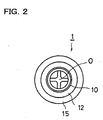
- the vane members 14 are arranged between the ring members 12 and 13. As shown in FIG. 3, the vane members 14 are arranged radially from the center axis O of the plunger 1 and the vane members 14 are arranged around the center axis O of the plunger 1 at regular intervals and at central angles of 45° .
- An outer diameter D2 of the vane members 14 is also equal to the inner diameter D of the syringe barrel 20 of the later-described syringe 2 or slightly smaller than the inner diameter D of the syringe barrel 20.
- a flange 15 is formed at a rear end of the plunger 1 (the right end in FIG. 1). Further, between the flange 15 and the ring member 13, a rib 16 whose cross-sectional shape is a shape of a cross as shown in FIG. 4 is provided. Furthermore, a gripping ring member 17 is arranged near the front (near the left in FIG. 1) of the flange portion 15 at the rear end of the plunger 1. The gripping ring member 17 has also a discoidal shape around the center axis O of the plunger 1.
- a diameter D3 of the gripping ring member 17 is also equal to the inner diameter D of the syringe barrel 20 of the later-described syringe 2 or slightly smaller than the inner diameter D of the syringe barrel 20.
- the plunger 1 as described above can be integrally molded of plastic such as, for example, polypropylene.
- a lure lock portion 21 is provided, and the lure lock portion 21 is in a state of being covered by a cap 22 before the syringe 2 is used.
- the inner diameter D of the syringe barrel 20 is equal to the diameters D1 of the ring members 12 and 13, the diameter D3 of the gripping ring member 17, and the outer diameter D2 of the vane members 14 explained above, or slightly larger than the diameters D1 of the ring members 12 and 13, the diameter D3 of the gripping ring member 17, and the outer diameter D2 of the vane members 14.
- Material of the above-described syringe barrel 2 is plastic such as a cyclic polyolefin resin, for example.
- liquid 23 such as, for example, a contrast medium is filled.
- a gasket 25 having a substantially columnar shape is inserted in the syringe barrel 20 from an open rear end (the right end in FIG. 5) of the syringe barrel 20, and by the insertion of the gasket 25 in the syringe barrel 20, the liquid 23 is in a state of being sealed in the syringe barrel 20.
- An outer circumferential surface of the gasket 25 is in close contact with an inner surface of the syringe barrel 20, and thereby, the liquid 23 is not leaked from a part between the outer circumferential surface of the gasket 25 and the inner surface of the syringe barrel 20.
- a screw hole 26 into which the screw portion 10 formed at the tip of the aforesaid plunger 1 is screwed is formed.
- the tip of the plunger 1 according to the embodiment of the present invention is first inserted from the rear end of the syringe barrel 20.
- the gripping ring member 17 since the gripping ring member 17 is arranged near the front of the flange portion 15 at the rear end of the plunger 1, the gripping ring member 17 can be gripped when the plunger 1 is thus inserted from the rear end of the syringe barrel 1 and the plunger 1 can be easily inserted.
- an end of an extension tube 30, for example, is set at the lure lock portion 21 at the tip of syringe barrel 20.
- the gasket 25 is then pushed via the plunger 1 and thereby the liquid medicine 23 can be injected into an intended position in a body or the like through the extension tube 30.
- the whole plunger 1 is formed in a round rod shape having a diameter equal to the inner diameter D of the syringe barrel 20 or slightly smaller than the inner diameter D instead of providing the aforesaid ring members 12, 13, and 17 and vane members 14. If the whole plunger is so formed in the round rod shape, however, a so-called dimensional shrink is caused in dimensional finishing when molded, which makes it difficult to obtain a plunger of accurate size. Accordingly, if the plunger is structured to have the ring members 12, 13, and 17 and the vane members 14, as the plunger 1 explained in the embodiment of the present invention, such a dimensional shrink can be prevented and the plunger 1 of accurate size can be obtained.
Abstract
Description
- The present invention relates to a plunger for a syringe used for supporting and moving a gasket inserted in a syringe barrel.
- In a general syringe, a liquid medicine is inhaled into its syringe barrel when it is used, but recently a prefilled syringe in which the liquid medicine is previously filled in the syringe barrel was developed to reduce a working load at a medical site. A prefilled syringe in which a contrast medium is filled in its syringe barrel has also come into use lately. Moreover, a prefilled plastic syringe in which a contrast medium is previously filled in its plastic syringe having comparatively large capacity is also used these days.
- When such a syringe is used, a plunger is inserted from a rear end of the syringe barrel and a screw portion formed at a tip of the plunger is screwed in a rear face of a gasket so that the gasket is mounted at the tip of the plunger. The gasket is thus mounted at the tip of the plunger and the gasket is pushed via the plunger, which causes the liquid medicine to be injected into a body or the like. Further, since the contrast medium has comparatively high viscosity and resistance when the contrast medium is injected into the body via a blood-vessel, spinal cord, or the like is large, pressure injection is generally performed using a device such as an auto-injector in a case of using the syringe in which the contrast medium is filled.
- When the gasket is mounted at the tip of the plunger in this way, if a center axis of the syringe barrel and a center axis of the plunger are not in a state of coinciding with each other, the screw portion at the tip of the plunger cannot be smoothly screwed into the rear face of the gasket. However, it is not easy to make the center axis of the syringe barrel and the center axis of the plunger coincide with each other and the screw portion at the tip of the plunger is sometimes forced to be screwed into the rear face of the gasket in a state in which both of the center axes deviate from each other.
- However, if the gasket is mounted on the screw portion at the tip of the plunger in the state in which the center axis of the syringe barrel and the center axis of the plunger deviate from each other, the gasket at the tip of the plunger becomes in a skewed position (a position in which the center axis of the gasket deviates from the center axis of the plunger) and the gasket becomes unable to smoothly move in the syringe barrel, which causes a problem that performance in filling the liquid medicine deteriorates. In addition, as a result of the gasket being in the skewed position, clearance is made between an inner surface of the syringe barrel and an outer circumferential surface of the gasket and fluid leakage easily occurs from the clearance.
- It is an object of the present invention to provide a plunger for a syringe in which a gasket can be mounted on a screw portion at a tip of the plunger in a state in which a center axis of a syringe barrel and a center axis of the plunger are easily made to coincide with each other.
- In order to achieve the object, disclosed in
claim 1 is a plunger for a syringe used for supporting and moving a gasket inserted in a syringe barrel, which is characterized in that it comprises: a screw portion formed at a tip thereof for mounting the gasket; a pair of ring members arranged at an interval from each other at the rear of the screw portion around a center axis of the plunger; and a plurality of vane members arranged radially from the center axis of the plunger between the ring members, and that outer diameters of the ring members and the vane members are equal to an inner diameter of the syringe barrel or slightly smaller than the inner diameter. - In the plunger according to
claim 1, the interval between the pair of ring members arranged at the rear of the screw portion is preferably, for example, 0.5 mm or larger. As for the plunger according toclaim 1, when the syringe is used, the plunger is inserted from a rear end of the syringe barrel and outer circumferential surfaces of the pair of ring members arranged at the interval from each other at the rear of the screw portion and outer circumferential surfaces of the vane members abut on an inner surface of the syringe barrel to guide the plunger, which indicates that a center axis of the syringe barrel and the center axis of the plunger naturally become in a state of coinciding with each other when the plunger is inserted from the rear end of the syringe barrel. Therefore, using the plunger according toclaim 1, the center axis of the syringe barrel and the center axis of the plunger are made to coincide with each other easily without precise positioning, which makes it possible to mount the gasket at the tip of the plunger in a correct state (a position in which a center axis of the gasket coincides with the center axis of the plunger). As a result, the gasket can move smoothly in the syringe barrel, which prevents deterioration of performance in filling a liquid medicine and fluid leakage from a part between the inner surface of the syringe barrel and the outer circumferential surface of the gasket. - In the plunger according to
claim 1, it is also suitable that the liquid medicine is previously filled in the syringe barrel as described inclaim 2. Further, as described in claim 3, eight pieces of the vane members are arranged, for example, at regular intervals and at central angles of 45°. - In addition, as described in claim 4, it is also suitable that the plunger further comprises a flange portion formed at a rear end of the plunger; and one or two or more gripping ring members arranged near the front of the flange portion around the center axis of the plunger, and that outer diameters of the gripping ring members are equal to the inner diameter of the syringe barrel or slightly smaller than the inner diameter. Disclosed in claim 5 is a plunger for a syringe used for supporting and moving a gasket inserted in a syringe barrel, which is characterized in that it comprises: a screw portion formed at a tip thereof for mounting the gasket; a flange portion formed at a rear end thereof; and one or two or more gripping ring members arranged near the front of the flange portion around a center axis of the plunger, and that outer diameters of the gripping ring members are equal to an inner diameter of the syringe barrel or slightly smaller than the inner diameter.
- As for the plunger according to claims 4 and 5, when the plunger is inserted from a rear end of the syringe barrel, the gripping ring members can be gripped so that the tip of the plunger can be easily inserted.
-
- FIG. 1 is a side view of a plunger according to an embodiment of the present invention;
- FIG. 2 is a front view of the plunger seen from a tip of the plunger;
- FIG. 3 is a cross-sectional view taken along the A-A line in FIG. 1;
- FIG. 4 is a cross-sectional view taken along the B-B line in FIG. 1;
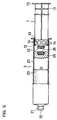
- FIG. 5 is an explanatory view in a state in which the plunger according to the embodiment of the present invention is inserted in a syringe; and
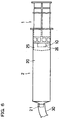
- FIG. 6 is an explanatory view in a state in which a gasket is mounted on the tip of the plunger,
-
- A preferred embodiment of the present invention will be explained below with reference to the drawings.
- At a tip of a
plunger 1, ascrew portion 10 for mounting agasket 25 provided in a later-describedsyringe 2 is formed. At the rear of the screw portion 10 (the right in FIG. 1), a pair ofring members vane members 14 are arranged between thering members ring members 12 is arranged in contact with thescrew portion 10 at the tip of theplunger 1 while the other one of thering members 13 is arranged at the rear of the one of thering members 12 at the interval therebetween, and the interval between thering members - Each of the
ring members plunger 1. Diameters D1 of thering members syringe barrel 20 of a later-describedsyringe 2 or slightly smaller than the inner diameter D of thesyringe barrel 20. - In this embodiment, eight pieces of the
vane members 14 are arranged between thering members vane members 14 are arranged radially from the center axis O of theplunger 1 and thevane members 14 are arranged around the center axis O of theplunger 1 at regular intervals and at central angles of 45° . An outer diameter D2 of thevane members 14 is also equal to the inner diameter D of thesyringe barrel 20 of the later-describedsyringe 2 or slightly smaller than the inner diameter D of thesyringe barrel 20. - At a rear end of the plunger 1 (the right end in FIG. 1), a
flange 15 is formed. Further, between theflange 15 and thering member 13, arib 16 whose cross-sectional shape is a shape of a cross as shown in FIG. 4 is provided. Furthermore, agripping ring member 17 is arranged near the front (near the left in FIG. 1) of theflange portion 15 at the rear end of theplunger 1. The grippingring member 17 has also a discoidal shape around the center axis O of theplunger 1. In addition, a diameter D3 of thegripping ring member 17 is also equal to the inner diameter D of thesyringe barrel 20 of the later-describedsyringe 2 or slightly smaller than the inner diameter D of thesyringe barrel 20. Theplunger 1 as described above can be integrally molded of plastic such as, for example, polypropylene. - As shown in FIG. 5, in the
syringe 2, at a tip (the left end in FIG. 5) of thesyringe barrel 20 which has a cylindrical shape, alure lock portion 21 is provided, and thelure lock portion 21 is in a state of being covered by acap 22 before thesyringe 2 is used. The inner diameter D of thesyringe barrel 20 is equal to the diameters D1 of thering members gripping ring member 17, and the outer diameter D2 of thevane members 14 explained above, or slightly larger than the diameters D1 of thering members gripping ring member 17, and the outer diameter D2 of thevane members 14. Material of the above-describedsyringe barrel 2 is plastic such as a cyclic polyolefin resin, for example. - In the
syringe barrel 20,liquid 23 such as, for example, a contrast medium is filled. Further, agasket 25 having a substantially columnar shape is inserted in thesyringe barrel 20 from an open rear end (the right end in FIG. 5) of thesyringe barrel 20, and by the insertion of thegasket 25 in thesyringe barrel 20, theliquid 23 is in a state of being sealed in thesyringe barrel 20. An outer circumferential surface of thegasket 25 is in close contact with an inner surface of thesyringe barrel 20, and thereby, theliquid 23 is not leaked from a part between the outer circumferential surface of thegasket 25 and the inner surface of thesyringe barrel 20. In a rear face of the gasket 25 (the right end face in FIG. 5), ascrew hole 26 into which thescrew portion 10 formed at the tip of theaforesaid plunger 1 is screwed is formed. - Here, when the
syringe 2 is used, the tip of theplunger 1 according to the embodiment of the present invention is first inserted from the rear end of thesyringe barrel 20. In this case, in theplunger 1 of the embodiment, since thegripping ring member 17 is arranged near the front of theflange portion 15 at the rear end of theplunger 1, thegripping ring member 17 can be gripped when theplunger 1 is thus inserted from the rear end of thesyringe barrel 1 and theplunger 1 can be easily inserted. - When the tip of the
plunger 1 is inserted from the rear end of thesyringe barrel 20 in this way, as shown in FIG. 5, outer circumferential surfaces of thering members vane members 14 abut on the inner surface of thesyringe barrel 20 to guide theplunger 1 so that the center axis O of theplunger 1 naturally becomes in a state in which it coincides with a center axis of thesyringe barrel 20. In the state in which the center axis O of theplunger 1 coincides with the center axis of thesyringe barrel 20, theplunger 1 is pushed straight into thesyringe barrel 20 and theplunger 1 is further turned to screw thescrew portion 10 at the tip of theplunger 1 into thescrew hole 26 on the rear face of thegasket 25 so that thegasket 25 can be mounted at the tip of theplunger 1 in a correct position (a position in which the center axis of thegasket 25 is made to coincide with the center axis of the plunger 1) as shown in FIG. 6. - On the other hand, as shown in FIG. 6, an end of an
extension tube 30, for example, is set at thelure lock portion 21 at the tip ofsyringe barrel 20. Thegasket 25 is then pushed via theplunger 1 and thereby theliquid medicine 23 can be injected into an intended position in a body or the like through theextension tube 30. - Although an example in which only one of the
gripping ring member 17 is provided near the front of theflange portion 15 at the rear end of theplunger 1 is explained in the embodiment shown in the drawings, two or more of thegripping ring members 17 may be provided near the front of theflange portion 15. Incidentally, an example of theplunger 1 in which the pair ofring members gripping ring member 17 are formed around the center axis O of theplunger 1 and thevane members 14 are arranged radially from the center axis O of theplunger 1 is explained above, but it can be also considered that the whole plunger is formed in a round rod shape having a diameter equal to the inner diameter D of thesyringe barrel 20 or slightly smaller than the inner diameter D instead of providing theaforesaid ring members vane members 14. If the whole plunger is so formed in the round rod shape, however, a so-called dimensional shrink is caused in dimensional finishing when molded, which makes it difficult to obtain a plunger of accurate size. Accordingly, if the plunger is structured to have thering members vane members 14, as theplunger 1 explained in the embodiment of the present invention, such a dimensional shrink can be prevented and theplunger 1 of accurate size can be obtained. - According to
claims 1 to 4, it becomes possible to make a center axis of a syringe barrel and a center axis of a plunger coincide with each other easily without precise positioning so that a gasket can be mounted at a tip of the plunger in a correct position in which a center axis of the gasket coincides with the center axis of the plunger. Therefore, when the syringe is used, the gasket can move in the syringe barrel smoothly, which prevents deterioration of performance in filling a liquid medicine and fluid leakage from a part between an inner surface of the syringe barrel and an outer circumferential surface of the gasket. Further, according to claims 4 and 5, when the plunger is inserted from a rear end of the syringe barrel, a gripping ring member can be gripped so that the tip of the plunger can be easily inserted. -
- 1
- plunger
- 2
- syringe
- 10
- screw portion
- 12, 13
- ring member
- 14
- vane member
- 15
- flange
- 16
- rib
- 17
- ring member
- 20
- syringe barrel
- 21
- lure lock portion
- 22
- cap
- 23
- liquid
- 25
- gasket
- 26
- screw hole
- 30
- extension tube
Claims (5)
- A plunger for a syringe used for supporting and moving a gasket inserted in a syringe barrel, comprising:wherein outer diameters of said ring members and said vane members are equal to an inner diameter of the syringe barrel or slightly smaller than the inner diameter.a screw portion formed at a tip thereof for mounting the gasket;a pair of ring members arranged at an interval from each other at a rear of said screw portion around a center axis of the plunger; anda plurality of vane members arranged radially from the center axis of the plunger between said ring members,
- A plunger for a syringe according to claim 1,
wherein a liquid medicine is previously filled in the syringe barrel. - A plunger for a syringe according to claim 1,
wherein eight pieces of said vane members are arranged at regular intervals and at central angles of 45° . - A plunger for a syringe according to claim 1, further comprising:wherein outer diameters of said gripping ring members are equal to the inner diameter of the syringe barrel or slightly smaller than the inner diameter.a flange portion formed at a rear end of the plunger; andone or two or more gripping ring members arranged near a front of the flange portion around the center axis of the plunger,
- A plunger for a syringe used for supporting and moving a gasket inserted in a syringe barrel, comprising:wherein outer diameters of said gripping ring members are equal to an inner diameter of the syringe barrel or slightly smaller than the inner diameter.a screw portion formed at a tip thereof for mounting the gasket;a flange portion formed at a rear end thereof; andone or two or more gripping ring members arranged near a front of said flange portion around a center axis of the plunger,
Applications Claiming Priority (3)
| Application Number | Priority Date | Filing Date | Title |
|---|---|---|---|
| JP20181499 | 1999-07-15 | ||
| JP20181499 | 1999-07-15 | ||
| PCT/JP2000/004754 WO2001005456A1 (en) | 1999-07-15 | 2000-07-14 | Plunger for syringe |
Publications (3)
| Publication Number | Publication Date |
|---|---|
| EP1205197A1 true EP1205197A1 (en) | 2002-05-15 |
| EP1205197A4 EP1205197A4 (en) | 2003-01-22 |
| EP1205197B1 EP1205197B1 (en) | 2005-10-26 |
Family
ID=16447358
Family Applications (1)
| Application Number | Title | Priority Date | Filing Date |
|---|---|---|---|
| EP00946344A Expired - Lifetime EP1205197B1 (en) | 1999-07-15 | 2000-07-14 | Plunger for syringe |
Country Status (7)
| Country | Link |
|---|---|
| US (1) | US7824380B2 (en) |
| EP (1) | EP1205197B1 (en) |
| JP (1) | JP4721314B2 (en) |
| AT (1) | ATE307629T1 (en) |
| CA (1) | CA2379409C (en) |
| DE (1) | DE60023511T2 (en) |
| WO (1) | WO2001005456A1 (en) |
Families Citing this family (37)
| Publication number | Priority date | Publication date | Assignee | Title |
|---|---|---|---|---|
| JP4737887B2 (en) * | 2001-08-16 | 2011-08-03 | テルモ株式会社 | Prefilled syringe |
| GB2414401B (en) | 2004-05-28 | 2009-06-17 | Cilag Ag Int | Injection device |
| GB2414409B (en) | 2004-05-28 | 2009-11-18 | Cilag Ag Int | Injection device |
| JP4990760B2 (en) * | 2004-05-28 | 2012-08-01 | シラグ・ゲーエムベーハー・インターナショナル | Injection device |
| GB2414406B (en) | 2004-05-28 | 2009-03-18 | Cilag Ag Int | Injection device |
| GB2414399B (en) | 2004-05-28 | 2008-12-31 | Cilag Ag Int | Injection device |
| GB2414775B (en) | 2004-05-28 | 2008-05-21 | Cilag Ag Int | Releasable coupling and injection device |
| GB2414403B (en) | 2004-05-28 | 2009-01-07 | Cilag Ag Int | Injection device |
| GB2414400B (en) | 2004-05-28 | 2009-01-14 | Cilag Ag Int | Injection device |
| GB2414402B (en) | 2004-05-28 | 2009-04-22 | Cilag Ag Int | Injection device |
| GB2425062B (en) | 2005-04-06 | 2010-07-21 | Cilag Ag Int | Injection device |
| GB2424836B (en) | 2005-04-06 | 2010-09-22 | Cilag Ag Int | Injection device (bayonet cap removal) |
| GB2427826B (en) | 2005-04-06 | 2010-08-25 | Cilag Ag Int | Injection device comprising a locking mechanism associated with integrally formed biasing means |
| DE602005018480D1 (en) | 2005-08-30 | 2010-02-04 | Cilag Gmbh Int | Needle device for a prefilled syringe |
| US20110098656A1 (en) | 2005-09-27 | 2011-04-28 | Burnell Rosie L | Auto-injection device with needle protecting cap having outer and inner sleeves |
| GB2438591B (en) | 2006-06-01 | 2011-07-13 | Cilag Gmbh Int | Injection device |
| GB2438593B (en) | 2006-06-01 | 2011-03-30 | Cilag Gmbh Int | Injection device (cap removal feature) |
| GB2438590B (en) | 2006-06-01 | 2011-02-09 | Cilag Gmbh Int | Injection device |
| BRPI0719556A2 (en) * | 2006-12-18 | 2013-12-10 | Daiichi Sankyo Co Ltd | EXTERNAL SYRINGE TUBE FOR FILLED CHEMICAL SOLUTION AND SEALED SYRINGE FORMULATION AND PROCESS FOR YOUR PRODUCTION |
| WO2009051124A1 (en) * | 2007-10-17 | 2009-04-23 | Ajinomoto Co., Inc. | Gasket, and its utilization |
| JP2009119171A (en) | 2007-11-19 | 2009-06-04 | Daikyo Seiko Ltd | Plunger rod and syringe |
| GB2461086B (en) | 2008-06-19 | 2012-12-05 | Cilag Gmbh Int | Injection device |
| GB2461087B (en) | 2008-06-19 | 2012-09-26 | Cilag Gmbh Int | Injection device |
| GB2461089B (en) | 2008-06-19 | 2012-09-19 | Cilag Gmbh Int | Injection device |
| GB2461084B (en) | 2008-06-19 | 2012-09-26 | Cilag Gmbh Int | Fluid transfer assembly |
| GB2461085B (en) | 2008-06-19 | 2012-08-29 | Cilag Gmbh Int | Injection device |
| KR101847792B1 (en) | 2008-11-26 | 2018-04-10 | 백톤 디킨슨 앤드 컴퍼니 | Single-use auto-disable syringe |
| GB2517896B (en) | 2013-06-11 | 2015-07-08 | Cilag Gmbh Int | Injection device |
| GB2515039B (en) | 2013-06-11 | 2015-05-27 | Cilag Gmbh Int | Injection Device |
| GB2515038A (en) | 2013-06-11 | 2014-12-17 | Cilag Gmbh Int | Injection device |
| GB2515032A (en) | 2013-06-11 | 2014-12-17 | Cilag Gmbh Int | Guide for an injection device |
| SI3131606T1 (en) * | 2014-04-14 | 2021-08-31 | Swedish Orphan Biovitrum Ab (Publ) | Syringe plunger rod |
| DE102015000999A1 (en) * | 2015-01-27 | 2016-07-28 | Sarl Omsi | Piston for spraying and spraying |
| CA2978090C (en) * | 2015-03-02 | 2023-12-12 | Fresenius Kabi Austria Gmbh | Plunger rod comprising at least three annular elements for a prefilled syringe |
| JP6827937B2 (en) | 2015-09-17 | 2021-02-10 | テルモ株式会社 | Plunger for syringe and prefilled syringe using it |
| DE102016200434A1 (en) | 2016-01-15 | 2017-07-20 | Schott Schweiz Ag | Piston rod for medical packaging |
| DE202017107724U1 (en) * | 2017-12-19 | 2019-03-21 | Wolfcraft Gmbh | Piston for a cartridge ejection device |
Citations (5)
| Publication number | Priority date | Publication date | Assignee | Title |
|---|---|---|---|---|
| US3828980A (en) * | 1972-11-06 | 1974-08-13 | Chem Dev Corp | Dispenser for precisely metered dispensing of viscous fluids |
| US4718463A (en) * | 1985-12-20 | 1988-01-12 | Mallinckrodt, Inc. | Method of producing prefilled sterile plastic syringes |
| WO1996014100A1 (en) * | 1994-11-03 | 1996-05-17 | Astra Pharmaceuticals Pty. Ltd. | Plastic syringe with overcap |
| WO1998017336A1 (en) * | 1996-10-18 | 1998-04-30 | Medrad, Inc. | Syringe, injector and injector system |
| US5752940A (en) * | 1994-01-25 | 1998-05-19 | Becton Dickinson And Company | Syringe and method for lyophilizing and reconstituting injectable medication |
Family Cites Families (8)
| Publication number | Priority date | Publication date | Assignee | Title |
|---|---|---|---|---|
| US4961728A (en) * | 1988-12-30 | 1990-10-09 | Becton, Dickinson And Company | Single-use syringe having misuse resistant features |
| JPH06327771A (en) * | 1993-05-25 | 1994-11-29 | Ishikawa Seisakusho:Kk | Syringe packed with liquid chemicals |
| WO1995034334A1 (en) * | 1994-06-15 | 1995-12-21 | Interventional Research Technologies, Inc. | Locking device for syringe or like instrument |
| US5460617A (en) * | 1994-07-28 | 1995-10-24 | Abbott Laboratories | Syringe plunger with intermediate pushing surface |
| US5688252A (en) * | 1994-09-30 | 1997-11-18 | Takeda Chemical Industries, Ltd. | Syringe |
| JPH09308689A (en) * | 1996-05-21 | 1997-12-02 | Nihon Medi Physics Co Ltd | Plunger having projection and syringe |
| IL122850A0 (en) * | 1998-01-05 | 1999-03-12 | Wizsoft | Pattern recognition using generalized association rules |
| US6331173B1 (en) | 1999-04-20 | 2001-12-18 | Pharmacia Ab | Device for displacing a member in a container |
-
2000
- 2000-07-14 JP JP2001510541A patent/JP4721314B2/en not_active Expired - Lifetime
- 2000-07-14 DE DE60023511T patent/DE60023511T2/en not_active Expired - Lifetime
- 2000-07-14 CA CA002379409A patent/CA2379409C/en not_active Expired - Lifetime
- 2000-07-14 WO PCT/JP2000/004754 patent/WO2001005456A1/en active IP Right Grant
- 2000-07-14 EP EP00946344A patent/EP1205197B1/en not_active Expired - Lifetime
- 2000-07-14 AT AT00946344T patent/ATE307629T1/en not_active IP Right Cessation
-
2007
- 2007-10-23 US US11/976,245 patent/US7824380B2/en not_active Expired - Fee Related
Patent Citations (5)
| Publication number | Priority date | Publication date | Assignee | Title |
|---|---|---|---|---|
| US3828980A (en) * | 1972-11-06 | 1974-08-13 | Chem Dev Corp | Dispenser for precisely metered dispensing of viscous fluids |
| US4718463A (en) * | 1985-12-20 | 1988-01-12 | Mallinckrodt, Inc. | Method of producing prefilled sterile plastic syringes |
| US5752940A (en) * | 1994-01-25 | 1998-05-19 | Becton Dickinson And Company | Syringe and method for lyophilizing and reconstituting injectable medication |
| WO1996014100A1 (en) * | 1994-11-03 | 1996-05-17 | Astra Pharmaceuticals Pty. Ltd. | Plastic syringe with overcap |
| WO1998017336A1 (en) * | 1996-10-18 | 1998-04-30 | Medrad, Inc. | Syringe, injector and injector system |
Non-Patent Citations (1)
| Title |
|---|
| See also references of WO0105456A1 * |
Also Published As
| Publication number | Publication date |
|---|---|
| EP1205197A4 (en) | 2003-01-22 |
| DE60023511D1 (en) | 2005-12-01 |
| EP1205197B1 (en) | 2005-10-26 |
| DE60023511T2 (en) | 2006-04-20 |
| CA2379409A1 (en) | 2001-01-25 |
| CA2379409C (en) | 2007-05-15 |
| WO2001005456A1 (en) | 2001-01-25 |
| JP4721314B2 (en) | 2011-07-13 |
| US7824380B2 (en) | 2010-11-02 |
| ATE307629T1 (en) | 2005-11-15 |
| US20080051728A1 (en) | 2008-02-28 |
Similar Documents
| Publication | Publication Date | Title |
|---|---|---|
| EP1205197A1 (en) | Plunger for syringe | |
| EP0111724B1 (en) | Variable sealing pressure plunger rod assembly | |
| US4664655A (en) | High viscosity fluid delivery system | |
| JP3296025B2 (en) | Drug-filled syringe | |
| US9211375B2 (en) | Syringe assembly and package for distribution of same | |
| US4543093A (en) | Variable sealing pressure plunger rod assembly | |
| US4758234A (en) | High viscosity fluid delivery system | |
| EP2060290A1 (en) | Plunger rod and syringe | |
| US10702653B2 (en) | Syringe holder and pharmaceutical liquid administration set | |
| KR102299431B1 (en) | Syringe and syringe set | |
| AU2016219904B2 (en) | Syringe systems, piston seal systems, stopper systems, and methods of use and assembly | |
| WO2015033951A1 (en) | Outer tube for syringe and mold for injection molding | |
| US9757526B2 (en) | Drug administration instrument | |
| JP3088706U (en) | Cartridge retainer assembly | |
| CN112638452A (en) | Needle hub and syringe device | |
| JP2003159330A (en) | Gasket for medical instrument and manufacturing method of medical instrument using it and gasket for medical instrument | |
| JP6228415B2 (en) | Syringe and medical syringe | |
| JPS6128627Y2 (en) | ||
| JP3097798B2 (en) | Drug-filled syringe | |
| CN110538358A (en) | Medicine container for injection and prefilled medicine container for injection | |
| JP2019188037A (en) | Dual-chamber type container/syringe | |
| NZ230335A (en) | Direct fill syringe for the micro-administration of viscous fluids |
Legal Events
| Date | Code | Title | Description |
|---|---|---|---|
| PUAI | Public reference made under article 153(3) epc to a published international application that has entered the european phase |
Free format text: ORIGINAL CODE: 0009012 |
|
| 17P | Request for examination filed |
Effective date: 20020115 |
|
| AK | Designated contracting states |
Kind code of ref document: A1 Designated state(s): AT BE CH CY DE DK ES FI FR GB GR IE IT LI LU MC NL PT SE |
|
| RIC1 | Information provided on ipc code assigned before grant |
Free format text: 7A 61M 5/315 A |
|
| A4 | Supplementary search report drawn up and despatched |
Effective date: 20021210 |
|
| AK | Designated contracting states |
Kind code of ref document: A4 Designated state(s): AT BE CH CY DE DK ES FI FR GB GR IE IT LI LU MC NL PT SE |
|
| 17Q | First examination report despatched |
Effective date: 20030424 |
|
| GRAP | Despatch of communication of intention to grant a patent |
Free format text: ORIGINAL CODE: EPIDOSNIGR1 |
|
| GRAS | Grant fee paid |
Free format text: ORIGINAL CODE: EPIDOSNIGR3 |
|
| GRAA | (expected) grant |
Free format text: ORIGINAL CODE: 0009210 |
|
| AK | Designated contracting states |
Kind code of ref document: B1 Designated state(s): AT BE CH CY DE DK ES FI FR GB GR IE IT LI LU MC NL PT SE |
|
| PG25 | Lapsed in a contracting state [announced via postgrant information from national office to epo] |
Ref country code: FI Free format text: LAPSE BECAUSE OF FAILURE TO SUBMIT A TRANSLATION OF THE DESCRIPTION OR TO PAY THE FEE WITHIN THE PRESCRIBED TIME-LIMIT Effective date: 20051026 Ref country code: AT Free format text: LAPSE BECAUSE OF FAILURE TO SUBMIT A TRANSLATION OF THE DESCRIPTION OR TO PAY THE FEE WITHIN THE PRESCRIBED TIME-LIMIT Effective date: 20051026 Ref country code: NL Free format text: LAPSE BECAUSE OF FAILURE TO SUBMIT A TRANSLATION OF THE DESCRIPTION OR TO PAY THE FEE WITHIN THE PRESCRIBED TIME-LIMIT Effective date: 20051026 Ref country code: BE Free format text: LAPSE BECAUSE OF FAILURE TO SUBMIT A TRANSLATION OF THE DESCRIPTION OR TO PAY THE FEE WITHIN THE PRESCRIBED TIME-LIMIT Effective date: 20051026 |
|
| REG | Reference to a national code |
Ref country code: GB Ref legal event code: FG4D |
|
| REG | Reference to a national code |
Ref country code: CH Ref legal event code: NV Representative=s name: E. BLUM & CO. PATENTANWAELTE Ref country code: CH Ref legal event code: EP |
|
| REG | Reference to a national code |
Ref country code: IE Ref legal event code: FG4D |
|
| REF | Corresponds to: |
Ref document number: 60023511 Country of ref document: DE Date of ref document: 20051201 Kind code of ref document: P |
|
| PG25 | Lapsed in a contracting state [announced via postgrant information from national office to epo] |
Ref country code: DK Free format text: LAPSE BECAUSE OF FAILURE TO SUBMIT A TRANSLATION OF THE DESCRIPTION OR TO PAY THE FEE WITHIN THE PRESCRIBED TIME-LIMIT Effective date: 20060126 Ref country code: GR Free format text: LAPSE BECAUSE OF FAILURE TO SUBMIT A TRANSLATION OF THE DESCRIPTION OR TO PAY THE FEE WITHIN THE PRESCRIBED TIME-LIMIT Effective date: 20060126 Ref country code: SE Free format text: LAPSE BECAUSE OF FAILURE TO SUBMIT A TRANSLATION OF THE DESCRIPTION OR TO PAY THE FEE WITHIN THE PRESCRIBED TIME-LIMIT Effective date: 20060126 |
|
| PG25 | Lapsed in a contracting state [announced via postgrant information from national office to epo] |
Ref country code: ES Free format text: LAPSE BECAUSE OF FAILURE TO SUBMIT A TRANSLATION OF THE DESCRIPTION OR TO PAY THE FEE WITHIN THE PRESCRIBED TIME-LIMIT Effective date: 20060206 |
|
| PG25 | Lapsed in a contracting state [announced via postgrant information from national office to epo] |
Ref country code: PT Free format text: LAPSE BECAUSE OF FAILURE TO SUBMIT A TRANSLATION OF THE DESCRIPTION OR TO PAY THE FEE WITHIN THE PRESCRIBED TIME-LIMIT Effective date: 20060327 |
|
| NLV1 | Nl: lapsed or annulled due to failure to fulfill the requirements of art. 29p and 29m of the patents act | ||
| ET | Fr: translation filed | ||
| PG25 | Lapsed in a contracting state [announced via postgrant information from national office to epo] |
Ref country code: IE Free format text: LAPSE BECAUSE OF NON-PAYMENT OF DUE FEES Effective date: 20060714 |
|
| PG25 | Lapsed in a contracting state [announced via postgrant information from national office to epo] |
Ref country code: MC Free format text: LAPSE BECAUSE OF NON-PAYMENT OF DUE FEES Effective date: 20060731 |
|
| PLBE | No opposition filed within time limit |
Free format text: ORIGINAL CODE: 0009261 |
|
| STAA | Information on the status of an ep patent application or granted ep patent |
Free format text: STATUS: NO OPPOSITION FILED WITHIN TIME LIMIT |
|
| 26N | No opposition filed |
Effective date: 20060727 |
|
| REG | Reference to a national code |
Ref country code: IE Ref legal event code: MM4A |
|
| REG | Reference to a national code |
Ref country code: CH Ref legal event code: PFA Owner name: BRACCO INTERNATIONAL B.V. Free format text: BRACCO INTERNATIONAL B.V.#STRAWINSKYLAAN 3051#1077 ZX AMSTERDAM (NL) $ DAIKYO SEIKO, LTD.#38-2, SUMIDA 3-CHOME, SUMIDA-KU#TOKYO 131-0031 (JP) -TRANSFER TO- BRACCO INTERNATIONAL B.V.#STRAWINSKYLAAN 3051#1077 ZX AMSTERDAM (NL) $ DAIKYO SEIKO, LTD.#38-2, SUMIDA 3-CHOME, SUMIDA-KU#TOKYO 131-0031 (JP) |
|
| PG25 | Lapsed in a contracting state [announced via postgrant information from national office to epo] |
Ref country code: LU Free format text: LAPSE BECAUSE OF NON-PAYMENT OF DUE FEES Effective date: 20060714 |
|
| PG25 | Lapsed in a contracting state [announced via postgrant information from national office to epo] |
Ref country code: CY Free format text: LAPSE BECAUSE OF FAILURE TO SUBMIT A TRANSLATION OF THE DESCRIPTION OR TO PAY THE FEE WITHIN THE PRESCRIBED TIME-LIMIT Effective date: 20051026 |
|
| REG | Reference to a national code |
Ref country code: FR Ref legal event code: PLFP Year of fee payment: 17 |
|
| REG | Reference to a national code |
Ref country code: FR Ref legal event code: PLFP Year of fee payment: 18 |
|
| REG | Reference to a national code |
Ref country code: FR Ref legal event code: PLFP Year of fee payment: 19 |
|
| PGFP | Annual fee paid to national office [announced via postgrant information from national office to epo] |
Ref country code: IT Payment date: 20190726 Year of fee payment: 20 Ref country code: FR Payment date: 20190725 Year of fee payment: 20 Ref country code: DE Payment date: 20190729 Year of fee payment: 20 |
|
| PGFP | Annual fee paid to national office [announced via postgrant information from national office to epo] |
Ref country code: GB Payment date: 20190729 Year of fee payment: 20 |
|
| PGFP | Annual fee paid to national office [announced via postgrant information from national office to epo] |
Ref country code: CH Payment date: 20190801 Year of fee payment: 20 |
|
| REG | Reference to a national code |
Ref country code: DE Ref legal event code: R071 Ref document number: 60023511 Country of ref document: DE |
|
| REG | Reference to a national code |
Ref country code: CH Ref legal event code: PL |
|
| REG | Reference to a national code |
Ref country code: GB Ref legal event code: PE20 Expiry date: 20200713 |
|
| PG25 | Lapsed in a contracting state [announced via postgrant information from national office to epo] |
Ref country code: GB Free format text: LAPSE BECAUSE OF EXPIRATION OF PROTECTION Effective date: 20200713 |