EP1204481B1 - Shredding machine - Google Patents
Shredding machine Download PDFInfo
- Publication number
- EP1204481B1 EP1204481B1 EP00927413A EP00927413A EP1204481B1 EP 1204481 B1 EP1204481 B1 EP 1204481B1 EP 00927413 A EP00927413 A EP 00927413A EP 00927413 A EP00927413 A EP 00927413A EP 1204481 B1 EP1204481 B1 EP 1204481B1
- Authority
- EP
- European Patent Office
- Prior art keywords
- operating member
- housing
- slot
- drive
- shredding
- Prior art date
- Legal status (The legal status is an assumption and is not a legal conclusion. Google has not performed a legal analysis and makes no representation as to the accuracy of the status listed.)
- Expired - Lifetime
Links
- 230000007246 mechanism Effects 0.000 claims abstract description 26
- 239000000463 material Substances 0.000 claims abstract description 21
- 239000011345 viscous material Substances 0.000 claims abstract description 5
- 230000009471 action Effects 0.000 claims abstract description 3
- 238000013016 damping Methods 0.000 claims description 19
- 230000000994 depressogenic effect Effects 0.000 abstract 1
- 230000004913 activation Effects 0.000 description 1
- 230000008901 benefit Effects 0.000 description 1
- 238000010276 construction Methods 0.000 description 1
- 230000000881 depressing effect Effects 0.000 description 1
- 239000013536 elastomeric material Substances 0.000 description 1
- 239000012530 fluid Substances 0.000 description 1
- 230000003287 optical effect Effects 0.000 description 1
- 230000035945 sensitivity Effects 0.000 description 1
Images


Classifications
-
- B—PERFORMING OPERATIONS; TRANSPORTING
- B02—CRUSHING, PULVERISING, OR DISINTEGRATING; PREPARATORY TREATMENT OF GRAIN FOR MILLING
- B02C—CRUSHING, PULVERISING, OR DISINTEGRATING IN GENERAL; MILLING GRAIN
- B02C18/00—Disintegrating by knives or other cutting or tearing members which chop material into fragments
- B02C18/0007—Disintegrating by knives or other cutting or tearing members which chop material into fragments specially adapted for disintegrating documents
-
- B—PERFORMING OPERATIONS; TRANSPORTING
- B02—CRUSHING, PULVERISING, OR DISINTEGRATING; PREPARATORY TREATMENT OF GRAIN FOR MILLING
- B02C—CRUSHING, PULVERISING, OR DISINTEGRATING IN GENERAL; MILLING GRAIN
- B02C18/00—Disintegrating by knives or other cutting or tearing members which chop material into fragments
- B02C18/0007—Disintegrating by knives or other cutting or tearing members which chop material into fragments specially adapted for disintegrating documents
- B02C2018/0023—Switching devices
Definitions
- This invention is concerned with improvements in shredding machines.
- a conventional shredding machine (hereinafter referred to as being of the kind specified) comprises a housing in which a shredding mechanism is mounted, drive means being provided for the shredding mechanism. Mounted over the housing is a cover provided with a slot through which material to be shredded is fed, into engagement with shredding mechanism of the machine.
- Desirably sensing means is provided in the machine, to terminate operation of the drive means when the machine is not being used, or when use has been completed.
- a convenient sensing means which may conveniently be incorporated into the machine comprises an optical sensor, responsive to the presence of a sheet of paper in the slot to activate, or permit activation of the drive means, and to terminate operation of the drive means when the paper has passed through the slot.
- sensing means are expensive, and an alternative sensing means may be provided by a microswitch having an operating member which is spring-urged into an operative position in which it extends across the mouth. The operating member is thus engaged by the paper as it is inserted into the slot, to cause the microswitch to close and to cause operation of the shredding mechanism to commence.
- US-A-5167374 discloses a shredding machine comprising a housing, shredding mechanism, slot, an operating member and a motion damping device, said operating member (6) being urged into an operative position in which it extends across the mouth of the slot, to be moved to an inoperative position by entry of material to be shredded into the housing, to cause the shredding mechanism to operate.
- a shredding machine comprising:-
- the resilient means is provided by spring means by which the plunger of a microswitch is urged to its open condition.
- movement of the operating member to its inoperative position causes movement of the damping device against the plunger of the microswitch, causing the microswitch to adopt its closed condition, to cause the shredding mechanism to operate.
- the damping device retards movement of the resilient means, delaying switching of the microswitch for a short period of time sufficient to allow completion of passage of material into the shredding mechanism.
- the machine comprises control means in the housing for the drive motor, said control means comprising a microswitch having a plunger spring-urged into a circuit-open condition, the microswitch providing said resilient means whereby the operating member is urged into its operative position, and the motion damping device causing movement of the operating member under the action of the resilient means to its operative position, to be retarded.
- control means comprising a microswitch having a plunger spring-urged into a circuit-open condition, the microswitch providing said resilient means whereby the operating member is urged into its operative position, and the motion damping device causing movement of the operating member under the action of the resilient means to its operative position, to be retarded.
- the damping device is a rotary damping device comprising a shallow cylindrical housing, and a drive member mounted in the housing with a small clearance between the interior wall of the housing and the exterior wall of the drive member, there being a viscous material, such as a viscous oil or elastomeric material, in said space to retard rotary movement of the drive member within the housing.
- a drive arm extending generally diametrically of the device, one end of which engages the operating member, the other end of which engages the plunger of the microswitch.
- said operating arm is L-shaped, and conveniently the operating member is freely mounted for movement relative to the housing of the machine.
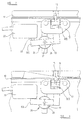
- the shredding machine which is the preferred embodiment of this invention is a machine of the kind specified, comprising a housing 4 within which is mounted shredding mechanism 5. Mounted in the housing 4 is a drive motor 6, and a motor controller 7. The housing comprises a cover 8 within which there is provided a material entry slot 10, through which material to be shredded may be fed into the housing, to be shredded by the shredding mechanism.
- a support bracket 12 Secured to the interior of the cover adjacent to the slot is a support bracket 12, which carries an operating member 14, mounted for movement therein between an operative position, in which a nose portion 15 extends across the slot (shown in Figures 1 and 2) and an inoperative position in which it does not.
- Resilient means is provided, as will be described hereinafter, to urge the operating member into its operative position.
- the machine comprises a microswitch 20 comprising a plunger 22 which is spring urged into a projecting position (shown in Figure 2), in which it is open circuit, and in which the shredding mechanism does not operate.
- a rotary damping device 26 comprising a cylindrical housing 28 providing a damping chamber 38, closed by a cover 39, within which chamber drive member 29 is mounted for rotary movement.
- a viscous fluid is provided, conveniently a viscous oil or a gel, to retard movement of the drive member 29 in the cylinder 28.
- the drive member is secured by an axial shaft 37, passing through the cover 39, to a drive arm 30, in the preferred embodiment of L-shape, one end portion 30 a of which is located adjacent to the plunger 22 of the microswitch, the opposite end portion 30 b of which is in engagement with the operating member 14.
- the spring means of the microswitch urges the plunger into its projecting position, causing the operating arm 30 to act on the operating member 14 to cause it to adopt its operative position, in which it projects across the slot 10.
- the rotary damping device retards movement of the plunger 22, and a short delay occurs before the microswitch adopts its off condition, causing operation of the shredding mechanism to be maintained for a short period of time - typically 1-2 seconds, after passage of the sheet beyond the nose 15.
- Such movement it will be appreciated simultaneously causes the nose portion 15 of the operating member 14 to move into the slot.
- the rotary damping device 126 is offset from the axis of rotation of the drive arm 130.
- the cylindrical drive member 129 is provided at its axis of rotation with a ring gear 88, engageable with gearing 98 provided on the drive arm 130, and extending partly around the axis of rotation of the drive arm 130.
- the period of delay will be relatively short, and may to some extent be determined by the geometry of the arrangement, in particular the distance between the plunger 22 of the microswitch and the longitudinal axis of the damping device, whereby the mechanical advantage may be changed.
- the period may be varied by changing the viscosity of the viscous material in the damping chamber.
Landscapes
- Engineering & Computer Science (AREA)
- Food Science & Technology (AREA)
- Crushing And Pulverization Processes (AREA)
- Portable Nailing Machines And Staplers (AREA)
- Luminescent Compositions (AREA)
- Iron Core Of Rotating Electric Machines (AREA)
- Control And Other Processes For Unpacking Of Materials (AREA)
- Numerical Control (AREA)
- Disintegrating Or Milling (AREA)
- Shovels (AREA)
Abstract
Description
Claims (9)
- A shredding machine comprising:-a) a housing (4);b) shredding mechanism (5) in the housing;c) a slot (10) in the housing (4), through which material to be shredded enters the housing; andd) an operating member (14) urged by resilient means (20) into an operative position in which it extends across the mouth of the slot (10), to be moved to an inoperative position by entry of the material (3) to be shredded into the housing, to cause the shredding mechanism (5) to operate,
characterised in that there is interposed between the resilient means (20) and the operating member (14) a motion damping device (26). - A shredding machine according to claim 1 wherein the resilient means (20) comprises spring means by which the plunger (22) of a microswitch (20) is urged to its open condition.
- A shredding machine according to claim 1 comprising a drive motor (6) in the housing to drive the shredding mechanism and control means (7) in the housing for the drive motor, said control means comprising a microswitch (20) having a plunger (22) spring-urged into a circuit-open condition; the microswitch (20) providing said resilient means whereby the operating member (14) is urged into its operative position, and the motion damping device (26) causing movement of the operating member (14) under the action of the resilient means (20) to its operative position to be retarded.
- A shredding machine according to any one of the preceding claims wherein the damping device (26) comprises a drive member (29), movement of which is retarded by the use of a viscous material.
- A shredding machine according to claim 4 wherein the operating member (14) is operative to move the drive member (29) in a cylindrical housing (28).
- A shredding machine according to claim 5 wherein the cylindrical housing (28) is shallow, and the drive member (29) is mounted in the housing with a small clearance (38) between the interior wall of the housing and the exterior wall of the drive member, a viscous material being provided in said space.
- A shredding machine according to any of the preceding claims 4, 5, 6 and 7 wherein the motion damping device (26) comprises a drive arm (30) connected to the drive member (29), one end (30b) of which engages the operating member (14), the other end (30a) of which engages the plunger (22) of the microswitch (20).
- A shredding machine according to claim 7 wherein said drive arm (30) is L-shaped.
- A shredding machine according to claim 1 wherein the motion damping device (26) comprises a cylindrical chamber (28), a drive member (29) mounted for rotary movement in the chamber (28), frictional resistance means in the chamber to retard movement of the drive member (29), said drive member (29) carrying a drive arm (30), one end (30b) of which engages an operating member (14), the other end (30a) engaging the plunger (22) of a microswitch (20).
Applications Claiming Priority (3)
| Application Number | Priority Date | Filing Date | Title |
|---|---|---|---|
| GBGB9919439.1A GB9919439D0 (en) | 1999-08-18 | 1999-08-18 | Shredding machine |
| GB9919439 | 1999-08-18 | ||
| PCT/GB2000/001463 WO2001012331A1 (en) | 1999-08-18 | 2000-04-17 | Shredding machine, and method of providing a time delay in a shredding machine |
Publications (2)
| Publication Number | Publication Date |
|---|---|
| EP1204481A1 EP1204481A1 (en) | 2002-05-15 |
| EP1204481B1 true EP1204481B1 (en) | 2004-06-16 |
Family
ID=10859308
Family Applications (1)
| Application Number | Title | Priority Date | Filing Date |
|---|---|---|---|
| EP00927413A Expired - Lifetime EP1204481B1 (en) | 1999-08-18 | 2000-04-17 | Shredding machine |
Country Status (7)
| Country | Link |
|---|---|
| US (1) | US6802465B1 (en) |
| EP (1) | EP1204481B1 (en) |
| AT (1) | ATE269165T1 (en) |
| AU (1) | AU4581900A (en) |
| DE (1) | DE60011626T2 (en) |
| GB (1) | GB9919439D0 (en) |
| WO (1) | WO2001012331A1 (en) |
Families Citing this family (20)
| Publication number | Priority date | Publication date | Assignee | Title |
|---|---|---|---|---|
| US6827300B2 (en) * | 2001-07-24 | 2004-12-07 | Primax Electronics, Ltd. | Automatic start mechanism of shredding apparatus |
| US7014133B2 (en) * | 2003-08-06 | 2006-03-21 | Ming-Hui Ho | Mechanical delaying device of shredder |
| US7631822B2 (en) | 2004-09-10 | 2009-12-15 | Fellowes Inc. | Shredder with thickness detector |
| US8870106B2 (en) | 2004-09-10 | 2014-10-28 | Fellowes, Inc. | Shredder with thickness detector |
| US7954737B2 (en) | 2007-10-04 | 2011-06-07 | Fellowes, Inc. | Shredder thickness with anti-jitter feature |
| US8672247B2 (en) | 2005-07-11 | 2014-03-18 | Fellowes, Inc. | Shredder with thickness detector |
| TWM314070U (en) * | 2006-11-30 | 2007-06-21 | Michilin Prosperity Co Ltd | Safety plate for paper feeding of movable shredder machine |
| GB2451513B (en) | 2007-08-02 | 2012-04-18 | Acco Uk Ltd | A shredding machine |
| CN201140095Y (en) * | 2007-11-20 | 2008-10-29 | 广州市阳光科密电子科技有限公司 | Double-inlet paper crusher |
| US7971812B2 (en) * | 2008-06-16 | 2011-07-05 | Michilin Prosperity Co., Ltd. | Power saving shredder |
| US8201761B2 (en) * | 2009-01-05 | 2012-06-19 | Fellowes, Inc. | Thickness sensor based motor controller |
| US8430347B2 (en) | 2009-01-05 | 2013-04-30 | Fellowes, Inc. | Thickness adjusted motor controller |
| US8505841B2 (en) * | 2009-01-11 | 2013-08-13 | Techtronic Floor Care Technology Limited | Anti-jamming assembly for shredders of sheet like material |
| US8091809B2 (en) * | 2009-03-24 | 2012-01-10 | Fellowes, Inc. | Shredder with jam proof system |
| US8205815B2 (en) | 2009-05-15 | 2012-06-26 | Fellowes, Inc. | Paper alignment sensor arrangement |
| US8550387B2 (en) | 2009-06-18 | 2013-10-08 | Tai Hoon K. Matlin | Restrictive throat mechanism for paper shredders |
| US8678305B2 (en) * | 2009-06-18 | 2014-03-25 | Fellowes, Inc. | Restrictive throat mechanism for paper shredders |
| US8382019B2 (en) | 2010-05-03 | 2013-02-26 | Fellowes, Inc. | In-rush current jam proof sensor control |
| US8511593B2 (en) | 2010-05-28 | 2013-08-20 | Fellowes, Inc. | Differential jam proof sensor for a shredder |
| WO2012040927A1 (en) * | 2010-09-30 | 2012-04-05 | Yang Meiying | Paper shredder |
Family Cites Families (3)
| Publication number | Priority date | Publication date | Assignee | Title |
|---|---|---|---|---|
| DE4103950C1 (en) * | 1991-02-09 | 1992-04-23 | Geha-Werke Gmbh, 3000 Hannover, De | |
| GB9601843D0 (en) | 1996-01-30 | 1996-04-03 | Acco Rexel Group Holdings Plc | Shredder with mechanical sensosr |
| US6250574B1 (en) * | 1999-04-07 | 2001-06-26 | Li-Ming Wu Huang | Device for monitoring paper shredding action of paper shredder |
-
1999
- 1999-08-18 GB GBGB9919439.1A patent/GB9919439D0/en not_active Ceased
-
2000
- 2000-04-17 AU AU45819/00A patent/AU4581900A/en not_active Abandoned
- 2000-04-17 DE DE60011626T patent/DE60011626T2/en not_active Expired - Fee Related
- 2000-04-17 AT AT00927413T patent/ATE269165T1/en not_active IP Right Cessation
- 2000-04-17 US US10/049,140 patent/US6802465B1/en not_active Expired - Lifetime
- 2000-04-17 EP EP00927413A patent/EP1204481B1/en not_active Expired - Lifetime
- 2000-04-17 WO PCT/GB2000/001463 patent/WO2001012331A1/en not_active Ceased
Also Published As
| Publication number | Publication date |
|---|---|
| ATE269165T1 (en) | 2004-07-15 |
| DE60011626D1 (en) | 2004-07-22 |
| AU4581900A (en) | 2001-03-13 |
| US6802465B1 (en) | 2004-10-12 |
| DE60011626T2 (en) | 2004-11-11 |
| EP1204481A1 (en) | 2002-05-15 |
| WO2001012331A1 (en) | 2001-02-22 |
| GB9919439D0 (en) | 1999-10-20 |
Similar Documents
| Publication | Publication Date | Title |
|---|---|---|
| US6802465B1 (en) | Shredding machine, and method of providing a time delay in a shredding machine | |
| US4448261A (en) | Motorized hand tool for drilling | |
| US4671364A (en) | Power-screwdriver device with variable torque adjustment | |
| JPS59182073A (en) | Electro-pneumatic type drilling hammer | |
| KR900701497A (en) | Nozzle touch device of injection molding machine | |
| KR910014179A (en) | Improved Metalwork Vise | |
| AU643336B2 (en) | Can opener | |
| KR960041697A (en) | Starting device of pinion retraction prevention structure | |
| EP1186560A3 (en) | Recording paper cutting mechanism | |
| EP1486349A3 (en) | Writing implement | |
| GB8618668D0 (en) | Door operating mechanism | |
| GB1014643A (en) | Devices for feeding paper, film or the like | |
| US4125182A (en) | Punch press controller | |
| KR930002049A (en) | Rotation control device and method of shaft | |
| JPS57157877A (en) | Motor driven actuator for opening and closing valve | |
| WO1999059779A8 (en) | Device for producing an abrupt feed motion | |
| KR970078396A (en) | Automatic paper feeder | |
| JPS57100085A (en) | Printing device | |
| KR870000860Y1 (en) | Typefeed Drive of Typewriter | |
| KR970069630A (en) | Collision Prevention System and Operation Method | |
| KR970049116A (en) | Power Clutch of Automatic Paper Feeding Device for Office Equipment | |
| KR970045972A (en) | Brake-actuated engine power shutoff | |
| KR970039593A (en) | Pressure Sensing and Airbag Drives | |
| MY123080A (en) | Geared motor | |
| KR970067006A (en) | Validation paper Automatic setting device |
Legal Events
| Date | Code | Title | Description |
|---|---|---|---|
| PUAI | Public reference made under article 153(3) epc to a published international application that has entered the european phase |
Free format text: ORIGINAL CODE: 0009012 |
|
| 17P | Request for examination filed |
Effective date: 20020206 |
|
| AK | Designated contracting states |
Kind code of ref document: A1 Designated state(s): AT BE CH CY DE DK ES FI FR GB GR IE IT LI LU MC NL PT SE |
|
| AX | Request for extension of the european patent |
Free format text: AL;LT;LV;MK;RO;SI |
|
| 17Q | First examination report despatched |
Effective date: 20030120 |
|
| RTI1 | Title (correction) |
Free format text: SHREDDING MACHINE |
|
| GRAP | Despatch of communication of intention to grant a patent |
Free format text: ORIGINAL CODE: EPIDOSNIGR1 |
|
| RAP1 | Party data changed (applicant data changed or rights of an application transferred) |
Owner name: ACCO UK LIMITED |
|
| GRAS | Grant fee paid |
Free format text: ORIGINAL CODE: EPIDOSNIGR3 |
|
| GRAA | (expected) grant |
Free format text: ORIGINAL CODE: 0009210 |
|
| AK | Designated contracting states |
Kind code of ref document: B1 Designated state(s): AT BE CH CY DE DK ES FI FR GB GR IE IT LI LU MC NL PT SE |
|
| PG25 | Lapsed in a contracting state [announced via postgrant information from national office to epo] |
Ref country code: IT Free format text: LAPSE BECAUSE OF FAILURE TO SUBMIT A TRANSLATION OF THE DESCRIPTION OR TO PAY THE FEE WITHIN THE PRESCRIBED TIME-LIMIT;WARNING: LAPSES OF ITALIAN PATENTS WITH EFFECTIVE DATE BEFORE 2007 MAY HAVE OCCURRED AT ANY TIME BEFORE 2007. THE CORRECT EFFECTIVE DATE MAY BE DIFFERENT FROM THE ONE RECORDED. Effective date: 20040616 Ref country code: NL Free format text: LAPSE BECAUSE OF FAILURE TO SUBMIT A TRANSLATION OF THE DESCRIPTION OR TO PAY THE FEE WITHIN THE PRESCRIBED TIME-LIMIT Effective date: 20040616 Ref country code: AT Free format text: LAPSE BECAUSE OF FAILURE TO SUBMIT A TRANSLATION OF THE DESCRIPTION OR TO PAY THE FEE WITHIN THE PRESCRIBED TIME-LIMIT Effective date: 20040616 Ref country code: LI Free format text: LAPSE BECAUSE OF FAILURE TO SUBMIT A TRANSLATION OF THE DESCRIPTION OR TO PAY THE FEE WITHIN THE PRESCRIBED TIME-LIMIT Effective date: 20040616 Ref country code: FI Free format text: LAPSE BECAUSE OF FAILURE TO SUBMIT A TRANSLATION OF THE DESCRIPTION OR TO PAY THE FEE WITHIN THE PRESCRIBED TIME-LIMIT Effective date: 20040616 Ref country code: BE Free format text: LAPSE BECAUSE OF FAILURE TO SUBMIT A TRANSLATION OF THE DESCRIPTION OR TO PAY THE FEE WITHIN THE PRESCRIBED TIME-LIMIT Effective date: 20040616 Ref country code: CH Free format text: LAPSE BECAUSE OF FAILURE TO SUBMIT A TRANSLATION OF THE DESCRIPTION OR TO PAY THE FEE WITHIN THE PRESCRIBED TIME-LIMIT Effective date: 20040616 |
|
| REG | Reference to a national code |
Ref country code: GB Ref legal event code: FG4D |
|
| REG | Reference to a national code |
Ref country code: CH Ref legal event code: EP |
|
| REF | Corresponds to: |
Ref document number: 60011626 Country of ref document: DE Date of ref document: 20040722 Kind code of ref document: P |
|
| REG | Reference to a national code |
Ref country code: IE Ref legal event code: FG4D |
|
| PG25 | Lapsed in a contracting state [announced via postgrant information from national office to epo] |
Ref country code: GR Free format text: LAPSE BECAUSE OF FAILURE TO SUBMIT A TRANSLATION OF THE DESCRIPTION OR TO PAY THE FEE WITHIN THE PRESCRIBED TIME-LIMIT Effective date: 20040916 Ref country code: SE Free format text: LAPSE BECAUSE OF FAILURE TO SUBMIT A TRANSLATION OF THE DESCRIPTION OR TO PAY THE FEE WITHIN THE PRESCRIBED TIME-LIMIT Effective date: 20040916 Ref country code: DK Free format text: LAPSE BECAUSE OF FAILURE TO SUBMIT A TRANSLATION OF THE DESCRIPTION OR TO PAY THE FEE WITHIN THE PRESCRIBED TIME-LIMIT Effective date: 20040916 |
|
| PG25 | Lapsed in a contracting state [announced via postgrant information from national office to epo] |
Ref country code: ES Free format text: LAPSE BECAUSE OF FAILURE TO SUBMIT A TRANSLATION OF THE DESCRIPTION OR TO PAY THE FEE WITHIN THE PRESCRIBED TIME-LIMIT Effective date: 20040927 |
|
| LTIE | Lt: invalidation of european patent or patent extension |
Effective date: 20040616 |
|
| NLV1 | Nl: lapsed or annulled due to failure to fulfill the requirements of art. 29p and 29m of the patents act | ||
| REG | Reference to a national code |
Ref country code: CH Ref legal event code: PL |
|
| ET | Fr: translation filed | ||
| PG25 | Lapsed in a contracting state [announced via postgrant information from national office to epo] |
Ref country code: CY Free format text: LAPSE BECAUSE OF FAILURE TO SUBMIT A TRANSLATION OF THE DESCRIPTION OR TO PAY THE FEE WITHIN THE PRESCRIBED TIME-LIMIT Effective date: 20050417 Ref country code: LU Free format text: LAPSE BECAUSE OF NON-PAYMENT OF DUE FEES Effective date: 20050417 |
|
| PG25 | Lapsed in a contracting state [announced via postgrant information from national office to epo] |
Ref country code: IE Free format text: LAPSE BECAUSE OF NON-PAYMENT OF DUE FEES Effective date: 20050418 |
|
| PLBE | No opposition filed within time limit |
Free format text: ORIGINAL CODE: 0009261 |
|
| STAA | Information on the status of an ep patent application or granted ep patent |
Free format text: STATUS: NO OPPOSITION FILED WITHIN TIME LIMIT |
|
| PG25 | Lapsed in a contracting state [announced via postgrant information from national office to epo] |
Ref country code: MC Free format text: LAPSE BECAUSE OF NON-PAYMENT OF DUE FEES Effective date: 20050430 |
|
| 26N | No opposition filed |
Effective date: 20050317 |
|
| PG25 | Lapsed in a contracting state [announced via postgrant information from national office to epo] |
Ref country code: PT Free format text: LAPSE BECAUSE OF NON-PAYMENT OF DUE FEES Effective date: 20041116 |
|
| PGFP | Annual fee paid to national office [announced via postgrant information from national office to epo] |
Ref country code: DE Payment date: 20080424 Year of fee payment: 9 Ref country code: FR Payment date: 20080312 Year of fee payment: 9 |
|
| PGFP | Annual fee paid to national office [announced via postgrant information from national office to epo] |
Ref country code: GB Payment date: 20080423 Year of fee payment: 9 |
|
| GBPC | Gb: european patent ceased through non-payment of renewal fee |
Effective date: 20090417 |
|
| REG | Reference to a national code |
Ref country code: FR Ref legal event code: ST Effective date: 20091231 |
|
| PG25 | Lapsed in a contracting state [announced via postgrant information from national office to epo] |
Ref country code: DE Free format text: LAPSE BECAUSE OF NON-PAYMENT OF DUE FEES Effective date: 20091103 |
|
| PG25 | Lapsed in a contracting state [announced via postgrant information from national office to epo] |
Ref country code: GB Free format text: LAPSE BECAUSE OF NON-PAYMENT OF DUE FEES Effective date: 20090417 Ref country code: FR Free format text: LAPSE BECAUSE OF NON-PAYMENT OF DUE FEES Effective date: 20091222 |