EP1204282A1 - Radio base station apparatus and radio communication method - Google Patents
Radio base station apparatus and radio communication method Download PDFInfo
- Publication number
- EP1204282A1 EP1204282A1 EP01932217A EP01932217A EP1204282A1 EP 1204282 A1 EP1204282 A1 EP 1204282A1 EP 01932217 A EP01932217 A EP 01932217A EP 01932217 A EP01932217 A EP 01932217A EP 1204282 A1 EP1204282 A1 EP 1204282A1
- Authority
- EP
- European Patent Office
- Prior art keywords
- communication terminal
- signal
- base station
- terminal apparatus
- channel
- Prior art date
- Legal status (The legal status is an assumption and is not a legal conclusion. Google has not performed a legal analysis and makes no representation as to the accuracy of the status listed.)
- Withdrawn
Links
Images






Classifications
-
- H—ELECTRICITY
- H04—ELECTRIC COMMUNICATION TECHNIQUE
- H04W—WIRELESS COMMUNICATION NETWORKS
- H04W48/00—Access restriction; Network selection; Access point selection
- H04W48/08—Access restriction or access information delivery, e.g. discovery data delivery
- H04W48/12—Access restriction or access information delivery, e.g. discovery data delivery using downlink control channel
-
- H—ELECTRICITY
- H04—ELECTRIC COMMUNICATION TECHNIQUE
- H04W—WIRELESS COMMUNICATION NETWORKS
- H04W16/00—Network planning, e.g. coverage or traffic planning tools; Network deployment, e.g. resource partitioning or cells structures
- H04W16/24—Cell structures
- H04W16/28—Cell structures using beam steering
-
- H—ELECTRICITY
- H04—ELECTRIC COMMUNICATION TECHNIQUE
- H04B—TRANSMISSION
- H04B7/00—Radio transmission systems, i.e. using radiation field
- H04B7/02—Diversity systems; Multi-antenna system, i.e. transmission or reception using multiple antennas
- H04B7/04—Diversity systems; Multi-antenna system, i.e. transmission or reception using multiple antennas using two or more spaced independent antennas
- H04B7/08—Diversity systems; Multi-antenna system, i.e. transmission or reception using multiple antennas using two or more spaced independent antennas at the receiving station
- H04B7/0837—Diversity systems; Multi-antenna system, i.e. transmission or reception using multiple antennas using two or more spaced independent antennas at the receiving station using pre-detection combining
- H04B7/0842—Weighted combining
- H04B7/0845—Weighted combining per branch equalization, e.g. by an FIR-filter or RAKE receiver per antenna branch
-
- H—ELECTRICITY
- H04—ELECTRIC COMMUNICATION TECHNIQUE
- H04B—TRANSMISSION
- H04B7/00—Radio transmission systems, i.e. using radiation field
- H04B7/02—Diversity systems; Multi-antenna system, i.e. transmission or reception using multiple antennas
- H04B7/04—Diversity systems; Multi-antenna system, i.e. transmission or reception using multiple antennas using two or more spaced independent antennas
- H04B7/08—Diversity systems; Multi-antenna system, i.e. transmission or reception using multiple antennas using two or more spaced independent antennas at the receiving station
- H04B7/0837—Diversity systems; Multi-antenna system, i.e. transmission or reception using multiple antennas using two or more spaced independent antennas at the receiving station using pre-detection combining
- H04B7/0842—Weighted combining
- H04B7/086—Weighted combining using weights depending on external parameters, e.g. direction of arrival [DOA], predetermined weights or beamforming
Definitions
- the present invention relates to a radio base station apparatus and wireless communication method in a digital wireless communication system.
- CDMA Code Division Multiple Access
- W-CDMA Wideband-CDMA
- DSCH Downlink Shared CHannel
- DSCH Downlink Shared CHannel
- DSCH is a channel for transmitting only data that is assigned to the plurality of terminals for each predetermined transmission unit (for example, each frame), and is a channel to perform fast data communications. Accordingly, DSCH is expected to be used in downlink fast packet transmission.
- a communication terminal using DSCH establishes a separate dedicated downlink channel (DCH: Dedicated CHannel), and using a known signal (for example, pilot signal) contained in a DCH signal, performs path search and channel estimation. Otherwise, such a terminal performs path search and channel estimation using a known signal of P-CPICH (Primary-Common Pilot Channel) common to each communication terminal.
- DCH Dedicated CHannel
- P-CPICH Primary-Common Pilot Channel
- An adaptive array antenna (hereinafter referred to as "AAA" when necessary) is sometimes used to reduce interference.
- An adaptive array antenna technique is to provide a base station with an array antenna comprised of a plurality of antenna elements so as to form a directivity while multiplying a received signal by a complex coefficient (hereinafter referred to as "weight”) to transmit signals according to the directivity.
- DSCH is a channel for transmitting only data that is assigned to a plurality of users for each predetermined transmission unit (for example, each frame), found out that when an adaptive array antenna is applied to DSCH signals, by using a channel applicable to the adaptive array antenna with DSCH and transmitting a known signal on the channel, a communication terminal using DSCH is capable of performing path search and channel estimation accurately, and then carried out the present invention.
- a base station determines a communication terminal apparatus that uses a shared channel that is common to all the communication terminals under control of a base station, based on a request signal in each of a plurality of uplink signals and which contains a request signal for requesting the use of the shared channel common, and transmits transmission data and supplemental common pilot channel signal to the determined communication terminal apparatus under the same directivity condition, and that the communication terminal apparatus that uses the shared channel performs path search and channel estimation accurately using the supplemental common pilot channel signal.
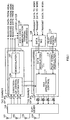
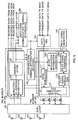
- FIG.1 is a block diagram illustrating a configuration of a radio base station apparatus according to the first embodiment of the present invention.
- Each direction-of-arrival estimating section 106 performs array combining processing on the received signals, further performs despreading on the combined signal, extracts the received signal from a corresponding communication terminal (user), and estimates the direction of arrival of the received signal from the communication terminal (user). Further, the received signal is demodulated in demodulation section 107 for the communication terminal to be received data.
- direction-of-arrival estimating sections 106 and demodulation sections 107 are provided for each communication terminal (MS), and demodulation sections 107 obtain respective received signals of communication terminals (MS#1 received signal to MS#n received signal).
- the demodulated signal is output to DSCH using communication terminal determining section 108.
- DSCH using communication terminal determining section 108 determines communication terminals that use DSCH, based on communication terminals that transmit a request signal to use DSCH, and information of an upper layer on communication terminal permitted to use DSCH. Further, DSCH using communication terminal determining section 108 outputs the determined information to data selecting section 109.
- Data selecting section 109 selects data of the communication terminal assigned DSCH from respective transmit data of communication terminals (MS#1 transmit data - MS#n transmit data) to output to data modulation section 111.
- Data modulation section 111 performs modulation and spreading on the transmit data, and outputs the spread signal to AAA directivity control section 113.
- Pilot signal generating section 110 generates a pilot signal on S-CPICH, and outputs the pilot signal to pilot signal modulation section 112.
- Pilot signal modulation section 112 performs modulation and spreading on the pilot signal, and outputs the spread pilot signal to AAA directivity control section 113.
- data modulation sections 111, pilot signal modulation sections 112, and AAA directivity control sections 113 are provided for each communication terminal (MS).
- AAA directivity control section 113 generates a transmit directivity based on the information on the direction of arrival estimated in direction-of-arrival estimating section 106.
- the signal from data modulation section 111 and the signal from pilot signal modulation section 112 each are multiplied by each of respective weights (for antennas 101 to 104) corresponding to the directivity, and respective signals are transmitted through duplexer 105 from antennas 101 to 104 to the communication terminal.
- demodulation section 107 demodulates the request signal to output to DSCH using communication terminal determining section 108.
- DSCH using communication terminal determining section 108 determines a communication terminal to be permitted to use DSCH based on request signals from communication terminals and information (priority information and channel state) of the upper layer.
- the section 108 since request signals are all output to DSCH using communication terminal determining section 108, the section 108 is capable of grasping communication terminals desiring to use DSCH. Further, since from the upper layer DSCH using communication terminal determining section 108 receives the information of which communication terminal has a higher priority to use DSCH, the section 108 determines the communication terminal to use DSCH according to the priority. In addition, on the upper layer, for example, channel states are monitored, and the priority is predetermined so that a communication terminal with the good channel state has a higher priority.
- DSCH using communication terminal determining section 108 notifies the request information on the upper layer, and that on the upper layer, a communication terminal to be permitted to use DSCH is determined and the determined information is notified to the section 108. Furthermore, it may be possible that DSCH using communication terminal determining section 108 itself makes the determination.
- the section 108 When DSCH using communication terminal determining section 108 has determined the communication terminal that uses DSCH, the section 108 outputs the information to data selecting section 109. Since transmit data for communication terminals (MS#1 transmit data to MS#n transmit data) are all input to data selecting section 109, the section 109 selects only transmit data for the communication terminal assigned DSCH from the input transmit data to output to data modulation section 111. Data modulation section 111 modulates the transmit data for the communication terminal assigned DSCH, and spreads the modulated transmit data with a predetermined spreading code.
- Pilot signal generating section 110 generates a pilot signal on S-CPIH and outputs the pilot signal to pilot signal modulation section 112.
- Pilot signal modulation section 112 modulates the pilot signal, and spreads the modulated pilot signal with a spreading code different from that used in the transmit data.
- the spread transmit data on DSCH and spread pilot signal are output to AAA directivity control section 113.
- AAA directivity control section 113 controls the directivity to the communication terminal to transmit DSCH signals, based on the direction of arrival estimated from the received signal of the communication terminal. That is, AAA directivity control section 113 calculates weights to direct a beam to the communication terminal to transmit DSCH signals, and a multiplier multiplies each of the transmit data and pilot signal for the communication terminal to transmit DSCH signals by each of the calculated weights.
- the weighted transmit data and pilot signals are transmitted to the communication terminal that the directivity is directed to, i.e., the communication terminal that uses DSCH.
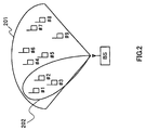
- FIG.2 is a diagram illustrating an omnidirectional transmit area and radiation pattern.
- Base station BS transmits a P-CPICH pilot signal with no directivity to all users, i.e., communication terminals #1 to #9.
- Reference numeral 201 denotes the omnidirectional transmit area.
- a DSCH signal and S-CPICH signal are coupled, i.e., multiplexed, and the resultant signal is transmitted to the communication terminal (herein communication terminal #1) that uses DSCH.
- Reference numeral 202 denotes the radiation pattern formed in the above-mentioned processing.
- S-CPICH is a common pilot channel to support P-CPICH and does not need to be transmitted always to the entire cell or sector. Therefore, signals on S-CPICH and DSCH are multiplexed and transmitted with the same directivity. It is thereby possible to perform the path search and channel estimation on DSCH using S-CPICH.
- FIG.4 is a block diagram illustrating a configuration of a radio base station apparatus according to the second embodiment of the present invention.
- the same sections as those in FIG.1 are assigned the same reference numerals as in FIG.1 to omit specific descriptions thereof.
- the radio base station apparatus illustrated in FIG.4 is further provided with communication terminal information selecting section 401 and spreading code determining section 402.
- Demodulation section 107 inputs the demodulated signal to communication terminal information selecting section 401.
- the section 401 acquires the information on modulation/demodulation capability (which modulation scheme is available) and modulation scheme from the demodulated signal, and outputs only the information of the communication terminal assigned DSCH determined in DSCH using communication terminal determining section 108 to spreading code determining section 402.
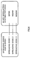
- Spreading code determining section 402 determines a spreading code to use by referring to the correspondence tables illustrated in FIG.6 based on the information on modulation/demodulation capability and modulation scheme.
- FIG.5 is a block diagram illustrating a configuration of a communication terminal apparatus that performs wireless communications with the above-mentioned radio base station apparatus.
- a downlink signal received through antenna 501 is subjected to the predetermine radio reception processing (such as downconverting and A/D conversion), and the processed signal is output to despreading sections 502 to 504 to be despread with a predetermined spreading code. All the despread results are output to despread result comparing section 505.
- predetermine radio reception processing such as downconverting and A/D conversion
- Received result comparing section 505 compares respective despread signals from despreading sections 502 to 504, and outputs the compared result (spreading code information) to M-ary modulation information estimating section 506.
- M-ary modulation information estimating section 506 estimates a modulation scheme applied to the DSCH signal, i.e., which M-ary modulation is applied. Then, the section 506 outputs the estimated information on M-ary modulation to data signal demodulation section 507. According to the information on M-ary modulation, data signal demodulation section 507 demodulates the DSCH signal by the M-ary demodulation scheme to obtain received data.
- Uplink signals from each communication terminal include the information on modulation/demodulation capability (which modulation scheme is available) and modulation scheme along with the request signal.
- the section 107 When demodulation section 107 demodulates the information on modulation/demodulation capability and modulation scheme, the section 107 outputs the information to communication terminal information selecting section 401.
- Communication terminal information selecting section 401 receives the information on the communication terminal that uses DSCH from DSCH using communication terminal determining section 108. Based on the information on the communication terminal that uses DSCH, communication terminal information selecting section 401 selects the information on modulation/demodulation capability and modulation scheme of the communication terminal that uses DSCH from respective information on modulation/demodulation capability and modulation scheme from communication terminals to output to spreading code determining section 402.
- spreading code determining section 402 refers to the correspondence tables illustrated in FIG.6 and determines the spreading code. For example, spreading code 1 is used when QPSK is indicated by the information on modulation/demodulation capability and modulation scheme of the communication terminal that uses DSCH, spreading code 2 is used when 16QAM is indicated by the information on modulation/demodulation capability and modulation scheme of the communication terminal that uses DSCH, and spreading code 3 is used when 64QAM is indicated by the information on modulation/demodulation capability and modulation scheme of the communication terminal that uses DSCH. It is herein assumed that the information on modulation/demodulation capability and modulation scheme is indicative of 16QAM and that spreading code 2 is used.
- the same correspondence tables illustrated in FIG.6 are stored in advance in the base station and communication terminal, and by referring to the tables, it is possible to determine the modulation scheme (the number of M-ary). Further, it may be also possible to broadcast the tables using a different channel.
- the S-CPICH signal generated in pilot signal generating section 110 is modulated, and is spread with the spreading code determined as described above.
- the transmit data for the communication terminal that uses DSCH is also modulated, and is spread with a predetermined spreading code.
- the spread DSCH transmit data and pilot signal are transmitted to the communication terminal that uses DSCH according to the directivity controlled in AAA directivity control section 113.
- the pilot signal among the received DSCH signal and S-CPICH pilot signal is subjected to the predetermined radio reception processing, and is despread in despreading sections 502 to 504 with spreading codes 1 to 3 (candidates for the spreading code used in the base station) in the correspondence table in FIG.6.
- despreading section 502 uses spreading code 1
- despreading section 503 uses spreading code 2
- despreading section 504 uses spreading code 3.
- despread result comparing section 505 specifies a spreading code that is used in the base station. Specifically, the section 505 compares the respective despread results of despreading sections 502 to 504. More specifically, for example, the integrated values (correlation values) of the despread results are compared. Since it is herein assumed that the base station performs spreading with spreading code 2, the correlation value of the despread result from despreading section 503 has the greatest value, and thereby it is determined that the spreading is performed with spreading code 2. The information indicative of spreading code 2 is output to M-ary modulation information estimating section 506.
- M-ary modulation information estimating section 506 confirms that the modulation scheme is 16QAM.
- the section 506 outputs the confirmed information indicative of the modulation scheme (16QAM) to data signal demodulation section 507.
- Data signal demodulation section 507 demodulates the DSCH signal by the demodulation scheme (16QAM) determined in M-ary modulation information estimating section 506 to obtain received data.
- the DSCH signal has been subjected to the predetermined radio reception processing and to despreading with the spreading code used in the base station.
- the communication terminal that uses DSCH is capable of confirming the modulation scheme by identifying the spreading code. In this way the communication terminal is capable of demodulating DSCH signals with reliability.
- the base station is capable of varying the M-ary modulation scheme when necessary to transmit signals.
- the information to demodulate DSCH signals is notified to the communication terminal using DSCH in real time within a period of time the channel state is not changed.
- despreading sections 502 to 504 are provided for each spreading code. Further, in the present invention it may be possible to provide one despreading section. In this case, the S-CPICH signal is divided into portions corresponding to different spreading codes, the despreading section performs the despreading with different spreading codes at respective different periods, and the respective despread results of the different spreading codes are compared.
- FIG.7 is a block diagram illustrating a configuration of a radio base station apparatus according to the third embodiment of the present invention.
- the same sections as those in FIG.1 are assigned the same reference numerals as in FIG.1 to omit specific descriptions thereof.
- the radio base station apparatus illustrated in FIG.7 is further provided with communication terminal information selecting section 401.
- Demodulation section 107 inputs the demodulated signal to communication terminal information selecting section 401.
- the section 401 acquires the information on modulation/demodulation capability (which modulation scheme is available) and modulation scheme of a communication terminal from the demodulated signal, and outputs only the information of the communication terminal assigned DSCH determined in DSCH using communication terminal determining section 108 to pilot signal generating section 110.
- Pilot signal generating section 110 determines a pilot pattern by referring to the correspondence tables illustrated in FIG.9 based on the information on modulation/demodulation capability and modulation scheme.
- FIG.8 is a block diagram illustrating a configuration of a communication terminal apparatus that performs wireless communications with the above-mentioned radio base station apparatus.
- a downlink signal received through antenna 801 is subjected to the predetermined radio reception processing (such as downconverting and A/D conversion), and the processed signal is despread with a predetermined spreading code used in the base station.
- the despread pilot signal is output to channel estimation sections 803 to 805 and is used in the channel estimation. All the channel estimation results are output to channel estimation result comparing section 806.
- Channel estimation result comparing section 806 compares respective channel estimation results in channel estimation sections 803 to 805, and outputs the compared result (pilot pattern information) to M-ary modulation information estimating section 807. Based on the pilot pattern information, M-ary modulation information estimating section 807 estimates a modulation scheme applied to the DSCH signal, i.e., which M-ary modulation is applied. Then, the section 806 outputs the estimated information on M-ary modulation to data signal demodulation section 808. Data signal demodulation section 808 demodulates the DSCH signal by the demodulation scheme corresponding to the information on M-ary modulation to obtain received data.
- Uplink signals from each communication terminal include the information on modulation/demodulation capability (which modulation scheme is available) and modulation scheme along with the request signal.
- the section 107 When demodulation section 107 demodulates the information on modulation/demodulation capability and modulation scheme, the section 107 outputs the information to communication terminal information selecting section 401.
- Communication terminal information selecting section 401 receives the information on the communication terminal that uses DSCH from DSCH using communication terminal determining section 108. Based on the information on the communication terminal that uses DSCH, communication terminal information selecting section 401 selects the information on modulation/demodulation capability and modulation scheme of the communication terminal that uses DSCH from respective information on modulation/demodulation capability and modulation scheme from communication terminals to output to pilot signal generating section 110.
- pilot signal generating section 110 refers to the correspondence tables illustrated in FIG.9 and determines the pilot pattern.
- pilot pattern 1 is used when QPSK is indicated by the information on modulation/demodulation capability and modulation scheme of the communication terminal that uses DSCH
- pilot pattern 2 is used when 16QAM is indicated by the information on modulation/demodulation capability and modulation scheme of the communication terminal that uses DSCH
- pilot pattern 3 is used when 64QAM is indicated by the information on modulation/demodulation capability and modulation scheme of the communication terminal that uses DSCH. It is herein assumed that the information on modulation/demodulation capability and modulation scheme is indicative of 16QAM and that pilot pattern 2 is used.
- the same correspondence tables illustrated in FIG.9 are stored in advance in the base station and communication terminal, and by referring to the tables, it is possible to determine the modulation scheme (the number of M-ary).
- the S-CPICH pilot signal thus generated in pilot signal generating section 110 is modulated, and is spread with a predetermined spreading code. Also, the transmit data for the communication terminal that uses DSCH is modulated, and is spread with the predetermined spreading code.
- the spread DSCH transmit data and pilot signal are transmitted to the communication terminal that uses DSCH according to the directivity controlled in AAA directivity control section 113.
- the pilot signal among the received DSCH signal and S-CPICH pilot signal is subjected to the predetermined radio reception processing, is despread, and is demodulated in pilot signal demodulation section 802.
- the demodulated pilot signal is output to channel estimation sections 803 to 805 and subjected to channel estimation with pilot patterns 1 to 3 (candidates for the pilot pattern used in the base station) in the correspondence table in FIG.9.
- pilot patterns 1 to 3 candidates for the pilot pattern used in the base station
- channel estimation section 803 uses pilot pattern 1
- channel estimation section 804 uses pilot pattern 2
- channel estimation section 805 uses pilot pattern 3.
- Channel estimation result comparing section 806 specifies the pilot pattern used in the base station. Specifically, the section 806 compares the respective channel estimation results of channel estimation sections 803 to 805. More specifically, the section 806 calculates fluctuations of the respective channel estimation results of channel estimation sections 803 to 805, compares the fluctuations, and selects a channel estimation value with the smallest fluctuation. Since it is assumed that the base station uses pilot pattern 2 , the channel estimation result from channel estimation section 804 has the smallest fluctuation, and thereby it is determined that pilot pattern 2 is used. The information indicative of pilot pattern 2 is output to M-ary modulation information estimating section 807. Further, it is considered to perform channel estimation on the received signal with each pilot pattern in identifying the pilot pattern, and to select a greatest one from channel estimation values with pilot patterns.
- M-ary modulation information estimating section 807 confirms that the modulation scheme is 16 QAM, and outputs the confirmed information indicative of the modulation scheme (16QAM) to data signal demodulation section 808.
- Data signal demodulation section 808 demodulates the DSCH signal by the demodulation scheme (16QAM) determined in M-ary modulation information estimating section 807 to obtain received data.
- the DSCH signal has been subjected to the predetermined radio reception processing and to despreading with the spreading code used in the base station.
- the communication terminal that uses DSCH is capable of confirming the modulation scheme by identifying the pilot pattern. In this way the communication terminal is capable of demodulating DSCH signals with reliability.
- the base station is capable of varying the M-ary modulation scheme when necessary to transmit signals.
- the information to demodulate DSCH signals is notified to the communication terminal using DSCH in real time within a period of time the channel state is not changed.
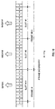
- the base station When transmitting signals to communication terminals that use DSCH, the base station transmits S-CPICH pilot signals with pilot patterns illustrated in FIG.10. For example, it is assumed that final slot #14 of frame #i has pilot pattern 1, first slot #0 of frame #i+1 has pilot pattern 2, and that second slot #1 of frame #i+1 has pilot pattern 3. In this case, the base station transmits QPSK-modulated DSCH signals to a communication terminal to which slot #14 is transmitted on DSCH, 16QAM-modulated DSCH signals to a communication terminal to which slot #0 is transmitted on DSCH, and 64QAM-modulated DSCH signals to a communication terminal to which slot #1 is transmitted on DSCH.
- a period of a time slot (a smallest unit for use in DSCH) is coincident with a period of a pilot pattern.
- Such a case is the most suitable in accuracy and efficiency for demodulating the information (M-ary modulation information) on modulation/demodulation capacity and modulation scheme.
- FIG.12 is a block diagram illustrating a configuration of a radio base station apparatus according to fourth embodiment of the present invention.
- the same sections as those in FIG.1 are assigned the same reference numerals as in FIG.1 to omit specific descriptions thereof.
- the radio base station apparatus illustrated in FIG.12 is further provided with communication terminal information selecting section 401, M-ary modulation information generating section 1201 and pilot signal combining section.
- Demodulation section 107 inputs the demodulated signal to communication terminal information selecting section 401.
- the section 401 acquires the information on modulation/demodulation capability (which modulation scheme is available) and modulation scheme of a communication terminal from the demodulated signal, and outputs only the information of the communication terminal assigned DSCH determined in DSCH using communication terminal determining section 108 to M-ary modulation information generating section 1210.
- M-ary modulation information generating section 1202 generates M-ary modulation information based on the information on modulation/demodulation capability and modulation scheme to output to pilot signal combining section 1202. Pilot signal combining section 1202 combines a pilot signal generated in pilot signal generating section 110 and the M-ary modulation information.
- FIG.13 is a block diagram illustrating a configuration of a communication terminal apparatus that performs wireless communications with the above-mentioned radio base station apparatus.
- a downlink signal received through antenna 1301 is subjected to the predetermined radio reception processing (such as downconverting and A/D conversion), and the processed signal is despread with a predetermined spreading code used in the base station.
- the despread pilot signal is demodulated in pilot signal demodulation section 1302.
- the despread pilot signal is also output to M-ary modulation signal demodulation section 1303 to demodulate an M-ary modulation signal inserted into the pilot signal.
- M-ary modulation signal demodulation section 1303 determines a modulation scheme based on the M-ary modulation signal, and then outputs the modulation scheme information to data signal demodulation section 1304. According to the modulation scheme information, data signal demodulation section 1304 demodulates DSCH signals to obtain received data.
- Uplink signals from each communication terminal include the information on modulation/demodulation capability (which modulation scheme is available) and modulation scheme along with the request signal.
- the section 107 When demodulation section 107 demodulates the information on modulation/demodulation capability and modulation scheme, the section 107 outputs the information to communication terminal information selecting section 401.
- Communication terminal information selecting section 401 receives the information on the communication terminal that uses DSCH from DSCH using communication terminal determining section 108. Based on the information on the communication terminal that uses DSCH, communication terminal information selecting section 401 selects the information on modulation/demodulation capability and modulation scheme of the communication terminal that uses DSCH from respective information on modulation/demodulation capability and modulation scheme from communication terminals to output to M-ary modulation information generating section 1202.
- M-ary modulation information generating section 1202 determines a modulation scheme (M-ary modulation information). It is herein assumed that the information on modulation/demodulation capability and modulation scheme is indicative of 16QAM.
- the M-ary modulation information is output to pilot signal combining section 1202. Pilot signal combining section 1202 inserts the M-ary modulation information into the pilot signal.
- the pilot signal is output to pilot signal modulation section 112.
- the modulated pilot signal is spread with a predetermined spreading code.
- the transmit data for the communication terminal that uses DSCH is modulated, and is spread with the predetermined spreading code.
- the spread DSCH transmit data and pilot signal are transmitted to the communication terminal that uses DSCH according to the directivity controlled in AAA directivity control section 113.
- the pilot signal among the received DSCH signal and S-CPICH pilot signal is subjected to the predetermined radio reception processing, is despread, and is demodulated in pilot signal demodulation section 1302.
- the M-ary modulation information inserted into the pilot signal is demodulated in M-ary modulation signal demodulation section 1303. In other words, it is determined that the M-ary modulation information is indicative of 16QAM as the modulation scheme.
- the determined information on modulation scheme (16QAM) is output to data signal demodulation section 1304.
- Data signal demodulation section 1304 demodulates DSCH signals by the demodulation scheme (16QAM) determined in M-ary modulation information demodulation section 1303 to obtain received data.
- the DSCH signals have been subjected to the predetermined radio reception processing and to despreading with the spreading code used in the base station.
- the communication terminal that uses DSCH is capable of confirming the modulation scheme by demodulating the M-ary modulation information.
- the communication terminal is capable of demodulating DSCH signals with reliability.
- the base station is capable of varying the M-ary modulation scheme when necessary to transmit signals.
- S-CPICH signals and DSCH signals are multiplexed, the information for use in demodulating DSCH signals is notified to the communication terminal using DSCH in real time within a period of time the channel state is not changed.
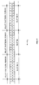
- the base station apparatus When transmitting signals to the communication terminal that uses DSCH, the base station apparatus transmits on S-CPICH pilot signals as illustrated in FIG.14. For example, M-ary modulation information is inserted into a slot for pilot signal in addition to a predetermined symbol sequence.
- the M-ary modulation information it is preferable to insert the M-ary modulation information to suit a period of time slots for DSCH (minimum unit for use by DSCH). That is, when DSCH time slots are composed of a few time slots, as illustrated in FIG.15, the M-ary modulation information is inserted every a few slots to suit the period. It is thereby possible to obtain the most suitable case in accuracy and efficiency for demodulating the information on modulation/demodulation capacity and modulation scheme. In addition, in the case where DSCH time slots are not separated into slots, it is possible to cope with such a case by inserting the M-ary modulation information into the corresponding DSCH time slots.
- the present invention is not limited to the above-mentioned embodiments 1 to 4, and is capable of being carried into practice with various modifications thereof.
- the above-mentioned embodiments 1 to 4 describe DSCH in W-CDMA
- the present invention is not limited to DSCH, and is capable of being applied to other channels shared by all the communication terminals under the control of a base station.
- such a channel is not limited particularly as long as the channel includes a pilot signal usable in demodulating DSCH signals and an adaptive array is applicable to the channel.
- the above-mentioned embodiments 1 to 4 describe the case of using a method for generating directivity to each communication terminal as the adaptive array technique.
- the present invention is capable of being applied to a case of grouping together a plurality of channels (users) using uplink signals and of using a common weight (group weight) in the same group.
- a radio base station apparatus of the present invention adopts a configuration provided with a determining section that determines a communication terminal apparatus that uses a shared channel based on a plurality of uplink request signals containing a request signal for using the shared channel shared by all communication terminals under control of the base station apparatus, a modulation section that modulates transmit data and a supplemental common pilot channel signal to be transmitted to the determined communication terminal apparatus, and a directivity control section that transmits the transmit data and the supplemental common pilot channel signal with the same directivity.
- the supplemental common pilot channel signal is used which does not need to be transmitted always to the entire cell or sector, such a pilot channel is coupled with the shared channel shared by all communication terminals under control of the base station to transmit signals with the same directivity. It is thereby possible to perform path search and channel estimation on the shared channel using the supplemental common pilot channel signal. As a result, it is possible to demodulate shared channel signals with reliability and to perform fast data communications using the shared channel.
- a radio base station apparatus of the present invention adopts a configuration provided with a determining section that determines a communication terminal apparatus that uses a shared channel based on a plurality of uplink request signals containing capability information on modulation scheme and a request signal for using the shared channel shared by all communication terminals under control of the base station apparatus, a spreading code selecting section that selects a spreading code for use in spreading a supplemental common pilot channel signal, based on the capability information of the determined communication terminal apparatus, and a directivity control section that transmits the transmit data and the supplemental common pilot channel signal to be transmitted to the determined communication terminal apparatus with the same directivity.
- the base station since the base station transmits the information on the modulation scheme to demodulate shared channel signals by using the spreading code on the supplemental common pilot channel, the base station is capable of notifying the communication terminal using the shared channel of the information to demodulate shared channel signals in real time within a period of time the channel state is not changed. As a result, the base station is capable of performing any M-ary modulation on shared channel signals to transmit.
- a radio base station apparatus of the present invention adopts a configuration provided with a determining section that determines a communication terminal apparatus that uses a shared channel based on a plurality of uplink request signals containing capability information on modulation scheme and a request signal for using the shared channel shared by all communication terminals under control of the base station apparatus, a pattern selecting section that selects a pilot pattern on a supplemental common pilot channel, based on the capability information of the determined communication terminal apparatus, and a directivity control section that transmits the transmit data and a signal on the supplemental common pilot channel to be transmitted to the determined communication terminal apparatus with the same directivity.
- the base station since the base station transmits the information on the modulation scheme to demodulate shared channel signals by using the pilot pattern on the supplemental common pilot channel, the base station is capable of notifying the communication terminal using the shared channel of the information to demodulate shared channel signals in real time within a period of time the channel state is not changed. As a result, the base station is capable of performing any M-ary modulation on shared channel signals to transmit.
- a radio base station apparatus of the present invention adopts a configuration provided with a determining section that determines a communication terminal apparatus that uses a shared channel based on a plurality of uplink request signals containing capability information on modulation scheme and a request signal for using the shared channel shared by all communication terminals under control of the base station apparatus, a control signal generating section that determines a modulation scheme based on the capability information of the determined communication terminal apparatus, generates a signal indicative of the determined modulation scheme, and inserts the generated signal as a control signal into a supplemental common pilot channel signal, and a directivity control section that transmits the transmit data and the supplemental common pilot channel signal to be transmitted to the determined communication terminal apparatus with the same directivity.
- the base station since the base station transmits the information on the modulation scheme to demodulate shared channel signals on the supplemental common pilot channel, the base station is capable of notifying the communication terminal using the shared channel of the information to demodulate shared channel signals in real time within a period of time the channel state is not changed. As a result, the base station is capable of performing any M-ary modulation on shared channel signals to transmit.
- a communication terminal apparatus of the present invention adopts a configuration provide with a despreading section that performs despreading on a downlink signal with each of all candidate spreading codes for a spreading code used in spreading a supplemental common pilot channel signal, a spreading code specifying section that compares despread results on the candidate spreading codes to specify the spreading code used in spreading the supplemental common pilot channel signal, and a demodulation section that demodulates downlink signals on a shared channel shared by all communication terminals under control of a base station, by a demodulation scheme corresponding to the specified spreading code.
- a communication terminal using the shared channel is capable of confirming the modulation scheme by identifying the spreading code.
- the communication terminal is thereby capable of demodulating signals on the shared channel with reliability.
- a communication terminal apparatus of the present invention adopts a configuration provide with a channel estimation section that performs channel estimation on a downlink signal with each of all candidate pilot patterns for a pilot pattern used on a supplemental common pilot channel, a pilot pattern specifying section that compares channel estimation results on the candidate pilot patterns to specify the pilot pattern used on the supplemental common pilot channel, and a demodulation section that demodulates downlink signals on a shared channel shared by all communication terminals under control of a base station, by a demodulation scheme corresponding to the specified pilot pattern.
- a communication terminal using the shared channel is capable of confirming the modulation scheme by identifying the pilot pattern.
- the communication terminal is thereby capable of demodulating signals on the shared channel with reliability.
- a communication terminal apparatus of the present invention adopts a configuration provided with a demodulation section that demodulates a control signal, inserted into a supplemental common pilot channel signal, indicative of a modulation scheme on downlink signals, and another demodulation section that demodulates downlink signals on a shared channel shared by all communication terminals under control of a base station, by a demodulation scheme corresponding to a demodulated result on the control signal.
- a communication terminal using the shared channel is capable of confirming the modulation scheme by identifying the signal inserted into the supplemental common pilot channel signal.
- the communication terminal is thereby capable of demodulating signals on the shared channel with reliability.
- a wireless communication method of the present invention has a determining step of determining a communication terminal apparatus that uses a shared channel based on a plurality of uplink request signals containing a request signal for using the shared channel shared by all communication terminals under control of a base station apparatus, a modulation step of modulating transmit data and a supplemental common pilot channel signal to be transmitted to the determined communication terminal apparatus, and a directivity control step of transmitting the transmit data and the supplemental common pilot channel signal with the same directivity.
- the supplemental common pilot channel signal is used which does not need to be transmitted always to the entire cell or sector, such a pilot channel is coupled with the shared channel shared by all communication terminals under control of the base station to transmit signals with the same directivity. It is there by possible to perform pathsearch and channel estimation on the shared channel using the supplemental common pilot channel signal. As a result, it is possible to demodulate shared channel signals with reliability and to perform fast data communications using the shared channel.
- a wireless communication method of the present invention has a determining step of determining a communication terminal apparatus that uses a shared channel based on a plurality of uplink request signals containing capability information on modulation scheme and a request signal for using the shared channel shared by all communication terminals under control of the base station apparatus, a spreading code selecting step of selecting a spreading code for use in spreading a supplemental common pilot channel signal, based on the capability information of the determined communication terminal apparatus, and a directivity control step of transmitting the transmit data and the supplemental common pilot channel signal to be transmitted to the determined communication terminal apparatus with the same directivity.
- the base station since the base station transmits the information on the modulation scheme to demodulate shared channel signals by using the spreading code on the supplemental common pilot channel, the base station is capable of notifying the communication terminal using the shared channel of the information to demodulate shared channel signals in real time within a period of time the channel state is not changed. As a result, the base station is capable of performing any M-ary modulation on shared channel signals to transmit.
- a wireless communication method of the present invention has a determining step of determining a communication terminal apparatus that uses a shared channel based on a plurality of uplink request signals containing capability information on modulation scheme and a request signal for using the shared channel shared by all communication terminals under control of the base station apparatus, a pattern selecting step of selecting a pilot pattern on supplemental common pilot channel, based on the capability information of the determined communication terminal apparatus, and a directivity control step of transmitting the transmit data and the supplemental common pilot channel signal to be transmitted to the determined communication terminal apparatus with the same directivity.
- the base station since the base station transmits the information on the modulation scheme to demodulate shared channel signals by using the pilot pattern on the supplemental common pilot channel, the base station is capable of notifying the communication terminal using the shared channel of the information to demodulate shared channel signals in real time within a period of time the channel state is not changed. As a result, the base station is capable of performing any M-ary modulation on shared channel signals to transmit.
- a wireless communication method of the present invention has a determining step of determining a communication terminal apparatus that uses a shared channel based on a plurality of uplink request signals containing capability information on modulation scheme and a request signal for using the shared channel shared by all communication terminals under control of the base station apparatus, a control signal generating step of determining a modulation scheme based on the capability information of the determined communication terminal apparatus, generating a signal indicative of the determined modulation scheme, and inserting the generated signal as a control signal into a supplemental common pilot channel signal, and a directivity control step of transmitting the transmit data and the supplemental common pilot channel signal to be transmitted to the determined communication terminal apparatus with the same directivity.
- the base station since the base station transmits the information on the modulation scheme to demodulate shared channel signals on the supplemental common pilot channel, the base station is capable of notifying the communication terminal using the shared channel of the information to demodulate shared channel signals in real time within a period of time the channel state is not changed. As a result, the base station is capable of performing any M-ary modulation on shared channel signals to transmit.
- the supplemental common pilot channel signal is used which does not need to be transmitted always to the entire cell or sector, such a pilot channel is coupled with the shared channel shared by all communication terminals under control of the base station to transmit signals with the same directivity. It is thereby possible to perform path search and channel estimation on the shared channel using the supplemental common pilot channel signal. As a result, it is possible to demodulate shared channel signals with reliability and to perform fast data communications using the shared channel.
- the present invention is applicable to a radio base station apparatus and wireless communication method in a digital wireless communication system.
Landscapes
- Engineering & Computer Science (AREA)
- Computer Networks & Wireless Communication (AREA)
- Signal Processing (AREA)
- Computer Security & Cryptography (AREA)
- Mobile Radio Communication Systems (AREA)
Abstract
Description
Claims (11)
- A radio base station apparatus comprising:determining means for determining a communication terminal apparatus that uses a shared channel that is common to all the communication terminals under control of a base station, based on a request signal in each of a plurality of uplink signals and which contains a request signal for requesting the use of the shared channel;modulation means for modulating transmission data and a supplemental common pilot channel signal to be transmitted to the determined communication terminal apparatus; anddirectivity control means for transmitting the transmission data and the supplemental common pilot channel signal under the same directivity condition.
- A radio base station apparatus comprising:determining means for determining a communication terminal apparatus that uses a shared channel that is common to all the communication terminals under control of a base station, based on a request signal in each of a plurality of uplink signals and which contains capability information on modulation scheme and a request signal for requesting the use of the shared channel;spreading code selecting means for selecting a spreading code for use in spreading a supplemental common pilot channel, based on the capability information of the determined communication terminal apparatus; anddirectivity control means for transmitting transmission data and the supplemental common pilot channel signal to be transmitted to the determined communication terminal apparatus under the same directivity condition.
- A radio base station apparatus comprising:determining means for determining a communication terminal apparatus that uses a shared channel that is common to all the communication terminals under control of a base station, based on a request signal in each of a plurality of uplink signals and which contains capability information on modulation scheme and a request signal for requesting the use of the shared channel;pattern selecting means for selecting a pilot pattern on a supplemental common pilot channel, based on the capability information of the determined communication terminal apparatus; anddirectivity control means for transmitting a transmission data and the supplemental common pilot channel signal to be transmitted to the determined communication terminal apparatus under the same directivity condition.
- A radio base station apparatus comprising:determining means for determining a communication terminal apparatus that uses a shared channel that is common to all the communication terminals under control of a base station, based on a request signal in each of a plurality of uplink signals and which contains capability information on modulation scheme and a request signal for requesting the use of the shared channel;control signal generating means for determining a modulation scheme based on the capability information of the determined communication terminal apparatus, generating a signal indicative of the determined modulation scheme, and inserting the generated signal as a control signal into a supplemental common pilot channel; anddirectivity control means for transmitting the transmission data and the supplemental common pilot channel signal to be transmitted to the determined communication terminal apparatus under the same directivity condition.
- A communication terminal apparatus comprising:despreading means for despreading a downlink signal with each of all candidate spreading codes for a spreading code used in spreading a supplemental common pilot channel;spreading code specifying means for comparing despread results on the candidate spreading codes to specify the spreading code used in spreading the supplemental common pilot channel; anddemodulation means for demodulating a downlink signal on a shared channel that is common to all communication terminals under control of a base station, by a demodulation scheme corresponding to the specified spreading code.
- A communication terminal apparatus comprising:channel estimation means for performing channel estimation on a downlink signal with each of all candidate pilot patterns for a pilot pattern used on a supplemental common pilot channel;pilot pattern specifying means for comparing channel estimation results on the candidate pilot patterns to specify the pilot pattern used on the supplemental common pilot channel; anddemodulation means for demodulating a downlink signal on a shared channel that is common to all communication terminals under control of a base station, by a demodulation scheme corresponding to the specified pilot pattern.
- A communication terminal apparatus comprising:first demodulation means for demodulating a control signal, inserted on a supplemental common pilot channel, indicative of a modulation scheme on a downlink signal; andsecond demodulation means for demodulating the downlink signal on a shared channel that is common to all communication terminals under control of a base station, by a demodulation scheme corresponding to a demodulated result on the control signal.
- A wireless communication method comprising:a determining step of determining a communication terminal apparatus that uses a shared channel that is common to all the communication terminals under control of a base station, based on a request signal in each of a plurality of uplink signals and which contains a request signal for requesting the use of the shared channel;a modulation step of modulating transmission data and a supplemental common pilot channel signal to be transmitted to the determined communication terminal apparatus; anda directivity control step of transmitting transmission data and the supplemental common pilot channel signal under the same directivity condition.
- A wireless communication method comprising:a determining step of determining a communication terminal apparatus that uses a shared channel that is common to all the communication terminals under control of a base station, based on a request signal in each of a plurality of uplink signals and which contains capability information on modulation scheme and a request signal for requesting the use of the shared channel;a spreading code selecting step of selecting a spreading code for use in spreading a supplemental common pilot channel, based on the capability information of the determined communication terminal apparatus; anda directivity control step of transmitting transmission data and the supplemental common pilot channel signal to be transmitted to the determined communication terminal apparatus under the same directivity condition.
- A wireless communication method comprising:a determining step of determining a communication terminal apparatus that uses a shared channel that is common to all the communication terminals under control of a base station, based on a request signal in each of a plurality of uplink signals and which contains capability information on modulation scheme and a request signal for requesting the use of the shared channel;a pattern selecting step of selecting a pilot pattern on a supplemental common pilot channel, based on the capability information of the determined communication terminal apparatus; anda directivity control step of transmitting transmission data and a signal on the supplemental common pilot channel to be transmitted to the determined communication terminal apparatus under the same directivity condition.
- A wireless communication method comprising:a determining step of determining a communication terminal apparatus that uses a shared channel that is common to all the communication terminals under control of a base station, based on a request signal in each of a plurality of uplink signals and which contains capability information on modulation scheme and a request signal for requesting the use of the shared channel;a control signal generating step of determining a modulation scheme based on the capability information of the determined communication terminal apparatus, generating a signal indicative of the determined modulation scheme, and inserting the generated signal as a control signal into a supplemental common pilot channel; anda directivity control step of transmitting the transmission data and the supplemental common pilot channel signal to be transmitted to the determined communication terminal apparatus with the same directivity.
Applications Claiming Priority (3)
| Application Number | Priority Date | Filing Date | Title |
|---|---|---|---|
| JP2000157430 | 2000-05-26 | ||
| JP2000157430A JP2001339758A (en) | 2000-05-26 | 2000-05-26 | Wireless base station device and wireless communication method |
| PCT/JP2001/004306 WO2001091491A1 (en) | 2000-05-26 | 2001-05-23 | Radio base station apparatus and radio communication method |
Publications (2)
| Publication Number | Publication Date |
|---|---|
| EP1204282A1 true EP1204282A1 (en) | 2002-05-08 |
| EP1204282A4 EP1204282A4 (en) | 2002-10-23 |
Family
ID=18662062
Family Applications (1)
| Application Number | Title | Priority Date | Filing Date |
|---|---|---|---|
| EP01932217A Withdrawn EP1204282A4 (en) | 2000-05-26 | 2001-05-23 | FIXED RADIO STATION APPARATUS AND RADIO COMMUNICATION METHOD |
Country Status (6)
| Country | Link |
|---|---|
| US (1) | US20020136187A1 (en) |
| EP (1) | EP1204282A4 (en) |
| JP (1) | JP2001339758A (en) |
| CN (1) | CN1593067A (en) |
| AU (1) | AU5881401A (en) |
| WO (1) | WO2001091491A1 (en) |
Cited By (4)
| Publication number | Priority date | Publication date | Assignee | Title |
|---|---|---|---|---|
| EP1553709A3 (en) * | 2000-12-21 | 2005-09-14 | Matsushita Electric Industrial Co., Ltd. | Wireless base station apparatus and wireless communication method |
| EP1343339A3 (en) * | 2002-03-05 | 2005-12-21 | NTT DoCoMo, Inc. | Channel structure having a shared downlink channel in a mobile communication system |
| WO2006134666A1 (en) | 2005-06-17 | 2006-12-21 | Fujitsu Limited | Wireless access method, wireless base station device, and wireless terminal device |
| EP2082492A4 (en) * | 2006-11-13 | 2015-12-16 | Ericsson Telefon Ab L M | METHOD AND ARRANGEMENT FOR CONTROL SIGNALING BASED ON PILOT MODEL IN SYSTEMS |
Families Citing this family (33)
| Publication number | Priority date | Publication date | Assignee | Title |
|---|---|---|---|---|
| CZ2002705A3 (en) | 2000-06-29 | 2002-07-17 | Matsushita Electric Industrial Co., Ltd. | Base station apparatus and radio communication method |
| JP2003244054A (en) * | 2002-02-21 | 2003-08-29 | Ntt Docomo Inc | Transmission control device and transmission control method |
| JP2003264490A (en) * | 2002-03-07 | 2003-09-19 | Matsushita Electric Ind Co Ltd | Radio base station apparatus and radio transmission method |
| WO2004032376A1 (en) * | 2002-10-07 | 2004-04-15 | Fujitsu Limited | Cdma communication apparatus |
| KR100900970B1 (en) | 2002-10-19 | 2009-06-08 | 삼성전자주식회사 | Mobile communication device and method including base station / mobile station multi-antenna |
| JP3929388B2 (en) * | 2002-11-11 | 2007-06-13 | 松下電器産業株式会社 | Base station apparatus and communication terminal apparatus |
| KR20070053655A (en) * | 2004-03-05 | 2007-05-25 | 넥스트넷 와이어리스 인크. | System and method for adaptive modulation |
| US7570621B2 (en) * | 2004-03-31 | 2009-08-04 | Motorola, Inc. | Method and apparatus for reducing erroneous frame classifications |
| DE102004021987A1 (en) | 2004-05-04 | 2005-11-24 | Wilo Ag | Removal of gases in radiators |
| JP4516358B2 (en) | 2004-05-26 | 2010-08-04 | 富士通株式会社 | Radio base station apparatus and radio communication method |
| JP4440739B2 (en) | 2004-09-06 | 2010-03-24 | 株式会社エヌ・ティ・ティ・ドコモ | Frequency sharing type transmitter |
| CN100578953C (en) * | 2004-11-08 | 2010-01-06 | 松下电器产业株式会社 | Wireless transmission device and pilot signal insertion method |
| US7894402B2 (en) * | 2005-04-15 | 2011-02-22 | Alcatel-Lucent Usa Inc. | High rate packet data spatial division multiple access (SDMA) |
| JP4713925B2 (en) * | 2005-04-18 | 2011-06-29 | 株式会社エヌ・ティ・ティ・ドコモ | Transmission rate control method, mobile station and radio base station |
| CN101032098B (en) * | 2005-07-25 | 2011-11-23 | 索尼株式会社 | Communication apparatus and method |
| WO2007086131A1 (en) * | 2006-01-27 | 2007-08-02 | Fujitsu Limited | Base station, wireless communication system, and pilot pattern deciding method |
| JP4688888B2 (en) * | 2006-01-27 | 2011-05-25 | 富士通株式会社 | Base station and radio communication system |
| ATE504448T1 (en) * | 2006-04-28 | 2011-04-15 | Telecom Italia Spa | INKJET PRINT HEAD BOARD AND PROCESS FOR PRODUCTION THEREOF |
| EP2028776A4 (en) * | 2006-06-07 | 2012-10-24 | Fujitsu Ltd | BASE STATION AND METHOD FOR ALLOCATING FREQUENCY TO A POLITE SEQUENCE |
| WO2008041546A1 (en) * | 2006-09-25 | 2008-04-10 | Panasonic Corporation | Radio communication device and pilot arrangement method |
| KR101265632B1 (en) * | 2006-12-12 | 2013-05-22 | 엘지전자 주식회사 | Method And Apparatus For Transmitting Reference Signal, Setting Reference Signal Transmission Pattern, And Setting And Allocating Resource Block |
| US20080159252A1 (en) * | 2006-12-29 | 2008-07-03 | Qi Bi | Method of coordinated transmission for broadcast-multicast services in high data rate networks |
| JP4864731B2 (en) * | 2007-01-09 | 2012-02-01 | Kddi株式会社 | Radio base station apparatus and radio terminal apparatus |
| US8509788B2 (en) * | 2007-03-08 | 2013-08-13 | Motorola Mobility Llc | Dynamic sharing of wireless resources among different communication networks |
| WO2009044704A1 (en) * | 2007-10-01 | 2009-04-09 | Ntt Docomo, Inc. | Base station device, transmission method, mobile station device, and reception method |
| US9264097B2 (en) * | 2009-06-04 | 2016-02-16 | Qualcomm Incorporated | Interference mitigation for downlink in a wireless communication system |
| US20130336193A1 (en) | 2012-06-19 | 2013-12-19 | Qualcomm Incorporated | Network information for assisting user equipment |
| US8908783B2 (en) * | 2009-10-21 | 2014-12-09 | Cisco Technology, Inc. | Scheduling collaborative uplink transmissions in OFDMA systems using multipath direction of arrival analysis |
| CN109379113B (en) | 2012-02-06 | 2021-12-21 | 日本电信电话株式会社 | Radio signal transmission method and radio apparatus |
| JP2013251841A (en) * | 2012-06-04 | 2013-12-12 | Hitachi Ltd | Radio communication base station |
| US8837649B2 (en) * | 2012-06-26 | 2014-09-16 | Qualcomm Incorporated | Non-primary pilot channel discovery for interference cancellation |
| JP6243115B2 (en) * | 2012-12-10 | 2017-12-06 | 株式会社Nttドコモ | Wireless base station, user terminal, and wireless communication method |
| US11268378B2 (en) * | 2018-02-09 | 2022-03-08 | Exxonmobil Upstream Research Company | Downhole wireless communication node and sensor/tools interface |
Family Cites Families (11)
| Publication number | Priority date | Publication date | Assignee | Title |
|---|---|---|---|---|
| JP2802870B2 (en) * | 1993-03-10 | 1998-09-24 | エヌ・ティ・ティ移動通信網株式会社 | Code division multiplex mobile communication apparatus and cell selection method for code division multiplex mobile communication |
| FI98172C (en) * | 1995-05-24 | 1997-04-25 | Nokia Telecommunications Oy | Method for transmitting a pilot signal and a cellular radio system |
| FI98171C (en) * | 1995-05-24 | 1997-04-25 | Nokia Telecommunications Oy | Procedure for transmitting pilot channels and cellular radio systems |
| JPH10145282A (en) * | 1996-11-12 | 1998-05-29 | N T T Ido Tsushinmo Kk | DS-CDMA transmission system |
| EP0888021A1 (en) * | 1997-06-24 | 1998-12-30 | Motorola, Inc. | TDMA communication system with a plurality of base stations in communication with mobile units via a radio interface comprising a dimensionable feedback channel |
| IT1295808B1 (en) * | 1997-11-04 | 1999-05-27 | Cselt Centro Studi Lab Telecom | PROCEDURE FOR THE ASSIGNMENT OF CHANNELS IN A COMMUNICATION SYSTEM BETWEEN MOBILE VEHICLES WITH MULTIPLE ACCESS TO DIVISION OF |
| US6208632B1 (en) * | 1998-01-29 | 2001-03-27 | Sharp Laboratories Of America | System and method for CDMA channel estimation |
| JP3266091B2 (en) * | 1998-03-04 | 2002-03-18 | 日本電気株式会社 | Cellular system |
| JP3798549B2 (en) * | 1998-03-18 | 2006-07-19 | 富士通株式会社 | Multi-beam antenna system for radio base station |
| AU2848699A (en) * | 1998-03-30 | 1999-10-18 | Northern Telecom Limited | Adaptive modulation for cdma systems |
| WO2001091318A1 (en) * | 2000-05-25 | 2001-11-29 | Samsung Electronics Co., Ltd | Apparatus and method for transmission diversity using more than two antennas |
-
2000
- 2000-05-26 JP JP2000157430A patent/JP2001339758A/en active Pending
-
2001
- 2001-05-23 EP EP01932217A patent/EP1204282A4/en not_active Withdrawn
- 2001-05-23 WO PCT/JP2001/004306 patent/WO2001091491A1/en not_active Ceased
- 2001-05-23 CN CNA018014003A patent/CN1593067A/en active Pending
- 2001-05-23 US US10/031,951 patent/US20020136187A1/en not_active Abandoned
- 2001-05-23 AU AU58814/01A patent/AU5881401A/en not_active Abandoned
Cited By (9)
| Publication number | Priority date | Publication date | Assignee | Title |
|---|---|---|---|---|
| EP1553709A3 (en) * | 2000-12-21 | 2005-09-14 | Matsushita Electric Industrial Co., Ltd. | Wireless base station apparatus and wireless communication method |
| US7392019B2 (en) | 2000-12-21 | 2008-06-24 | Matsushita Electric Industrial Co., Ltd. | Wireless base station apparatus and wireless communication method |
| EP1343339A3 (en) * | 2002-03-05 | 2005-12-21 | NTT DoCoMo, Inc. | Channel structure having a shared downlink channel in a mobile communication system |
| US7519028B2 (en) | 2002-03-05 | 2009-04-14 | Ntt Docomo, Inc. | Channel structure, method forming the same, radio base station, mobile station in mobile communication system |
| WO2006134666A1 (en) | 2005-06-17 | 2006-12-21 | Fujitsu Limited | Wireless access method, wireless base station device, and wireless terminal device |
| EP1895796A4 (en) * | 2005-06-17 | 2012-02-08 | Fujitsu Ltd | WIRELESS ACCESS METHOD, WIRELESS BASE STATION DEVICE, AND WIRELESS TERMINAL DEVICE |
| EP2082492A4 (en) * | 2006-11-13 | 2015-12-16 | Ericsson Telefon Ab L M | METHOD AND ARRANGEMENT FOR CONTROL SIGNALING BASED ON PILOT MODEL IN SYSTEMS |
| US9813211B2 (en) | 2006-11-13 | 2017-11-07 | Telefonaktiebolaget Lm Ericsson (Publ) | Method and arrangement for pilot pattern based control signaling in MIMO systems |
| US10298373B2 (en) | 2006-11-13 | 2019-05-21 | Telefonaktiebolaget Lm Ericsson (Publ) | Method and arrangement for pilot pattern based control signaling in MIMO systems |
Also Published As
| Publication number | Publication date |
|---|---|
| EP1204282A4 (en) | 2002-10-23 |
| AU5881401A (en) | 2001-12-03 |
| US20020136187A1 (en) | 2002-09-26 |
| WO2001091491A1 (en) | 2001-11-29 |
| JP2001339758A (en) | 2001-12-07 |
| CN1593067A (en) | 2005-03-09 |
Similar Documents
| Publication | Publication Date | Title |
|---|---|---|
| EP1204282A1 (en) | Radio base station apparatus and radio communication method | |
| US7801563B2 (en) | Radio base station apparatus and radio communication method | |
| US7321772B2 (en) | Mobile station, base station, communications system, and communication method | |
| EP1547419B1 (en) | Requesting and controlling access in a wireless communications network | |
| US7453854B2 (en) | Radio signal communication method, base station and terminal station | |
| KR100551113B1 (en) | Forward link transmission method and system for CDMA using steerable distributed antenna | |
| JP3583353B2 (en) | Communication terminal device and base station device | |
| US6717976B1 (en) | Method and apparatus for signal to noise power ratio estimation in a multi sub-channel CDMA receiver | |
| US20030223391A1 (en) | Method and system employing antenna arrays | |
| JP2004297750A (en) | Wireless communication system | |
| US6810070B1 (en) | Selective multi-carrier direct sequence spread spectrum communication systems and methods | |
| EP1456965B1 (en) | Parameter estimation for adaptive antenna system | |
| KR100435795B1 (en) | Radio base station device and radio communication method | |
| JP2001267987A (en) | Wireless base station device and wireless communication method | |
| KR100299128B1 (en) | Apparatus and method for power control bit pattern transmission and reception according to transmission antenna in mobile communication system | |
| JP4724180B2 (en) | Radio access method, radio base station apparatus and radio terminal apparatus | |
| KR20060099410A (en) | Switched beam selection method using maximum received power | |
| US8442442B2 (en) | Methods for assigning scrambling codes and reducing interference in telecommunications networks | |
| EP2058967A1 (en) | Spatial division multiple access for high speed packet access modes | |
| KR100374038B1 (en) | Device and method for diversity combining signals on common channel in cdma communication system | |
| KR20060031188A (en) | Beam forming method and apparatus in mobile communication system | |
| JP2000224096A (en) | Mobile communication system, radio base station and mobile communication terminal used in this mobile communication system | |
| CA2625425C (en) | Support of multiuser detection in the downlink | |
| KR20060031193A (en) | Method and apparatus for transmitting reception quality index of forward secondary pilot channel of mobile terminal | |
| KR20060014877A (en) | Beamforming method and apparatus using forward auxiliary pilot channel |
Legal Events
| Date | Code | Title | Description |
|---|---|---|---|
| PUAI | Public reference made under article 153(3) epc to a published international application that has entered the european phase |
Free format text: ORIGINAL CODE: 0009012 |
|
| AK | Designated contracting states |
Kind code of ref document: A1 Designated state(s): AT BE CH CY DE DK ES FI FR GB GR IE IT LI LU MC NL PT SE TR |
|
| AX | Request for extension of the european patent |
Free format text: AL;LT;LV;MK;RO;SI |
|
| 17P | Request for examination filed |
Effective date: 20020304 |
|
| A4 | Supplementary search report drawn up and despatched |
Effective date: 20020911 |
|
| AK | Designated contracting states |
Kind code of ref document: A4 Designated state(s): AT BE CH CY DE DK ES FI FR GB GR IE IT LI LU MC NL PT SE TR |
|
| 17Q | First examination report despatched |
Effective date: 20030113 |
|
| STAA | Information on the status of an ep patent application or granted ep patent |
Free format text: STATUS: THE APPLICATION IS DEEMED TO BE WITHDRAWN |
|
| RBV | Designated contracting states (corrected) |
Designated state(s): DE FR GB |
|
| 18D | Application deemed to be withdrawn |
Effective date: 20031216 |