EP1204127A2 - Mechanical and gate for interlocking electric power switches and distibution system incorporating same - Google Patents
Mechanical and gate for interlocking electric power switches and distibution system incorporating same Download PDFInfo
- Publication number
- EP1204127A2 EP1204127A2 EP01126251A EP01126251A EP1204127A2 EP 1204127 A2 EP1204127 A2 EP 1204127A2 EP 01126251 A EP01126251 A EP 01126251A EP 01126251 A EP01126251 A EP 01126251A EP 1204127 A2 EP1204127 A2 EP 1204127A2
- Authority
- EP
- European Patent Office
- Prior art keywords
- elongated
- pivot plate
- electric power
- coupling
- actuator
- Prior art date
- Legal status (The legal status is an assumption and is not a legal conclusion. Google has not performed a legal analysis and makes no representation as to the accuracy of the status listed.)
- Withdrawn
Links
Images


Classifications
-
- H—ELECTRICITY
- H01—ELECTRIC ELEMENTS
- H01H—ELECTRIC SWITCHES; RELAYS; SELECTORS; EMERGENCY PROTECTIVE DEVICES
- H01H9/00—Details of switching devices, not covered by groups H01H1/00 - H01H7/00
- H01H9/20—Interlocking, locking, or latching mechanisms
- H01H9/26—Interlocking, locking, or latching mechanisms for interlocking two or more switches
- H01H9/262—Interlocking, locking, or latching mechanisms for interlocking two or more switches using flexible transmission elements, e.g. Bowden cable
-
- H—ELECTRICITY
- H01—ELECTRIC ELEMENTS
- H01H—ELECTRIC SWITCHES; RELAYS; SELECTORS; EMERGENCY PROTECTIVE DEVICES
- H01H9/00—Details of switching devices, not covered by groups H01H1/00 - H01H7/00
- H01H9/20—Interlocking, locking, or latching mechanisms
- H01H9/26—Interlocking, locking, or latching mechanisms for interlocking two or more switches
- H01H2009/267—Interlocking, locking, or latching mechanisms for interlocking two or more switches with interlocking of two out of three switches, e.g. two switches each connecting a power supply to a busbar and a bus coupling switch interlocked in such a way that the power supplies are never connected in parallel
Definitions
- This invention relates to a mechanical device for interlocking multiple electric power switches in a distribution system which by providing a mechanical output only upon the occurrence of mechanical movement of both of two mechanical inputs.
- each circuit breaker is equipped with an output indication device which produces a motion when the breaker is closed and an input device which trips the breaker open, or holds it trip-free, when it receives an input signal in the form of a mechanical motion.
- One of the most complex mechanical interlocking schemes involves three interlocked circuit breakers, any two of which can be closed at once.
- An example of its use is a "double-ended" switchboard with two independent sources and a split main bus than can be connected with a "tie" breaker. It is desirable to prevent simultaneous connection of both sources to the main bus, unless the tie breaker is open. But, if either of the main breakers is open, the tie breaker can be closed, thus feeding the split bus from a single source.
- This form of three-way mechanical interlock requires an AND logic element. Each breaker receives an input signal (motion) from the other two. Either signal alone will not operate the tripping device; it takes the combination of both inputs to produce the output (trip) response.
- This mechanical AND gate should have characteristics which make it simple and inexpensive to produce and install. Because the AND gate will be used less frequently, it is desirable that it be adapted to be interchanged with the simple OR gate currently used in simpler interlock arrangements. For proper operation, the AND gate should respond with no rotation if one input alone is present and with full rotation if both inputs are present. For design commonality it is also desirable that the input motions used with the AND gate be of the same magnitude and direction as those used for the OR gate with which it can be interchanged.
- the mechanical AND gate comprises a pivot plate having an elongated slot.
- a first input coupling is mounted to the pivot plate at a point laterally offset to a first side of the elongated slot.
- a second input coupling is mounted to the pivot plate at a point laterally offset to a second side of the elongated slot.
- the output shaft of the gate extends transversely toward the pivot plate in alignment with the elongated slot.
- An output coupling mounted on but radially offset from the output shaft engages and is slideable relative to the pivot plate in the elongated slot.
- a first elongated actuator engages the first input coupling and is axially moveable between ON and OFF positions.
- a second elongated actuator engages the second input coupling and is also axially movable between ON and OFF positions.
- the first and second input couplings are structured to only transfer force from the respective elongated actuators to the pivot plate with movement toward the ON position so that the pivot plate slides relative to the output coupling engaging the elongated slot, when only one of the elongated actuators moves to the ON position yet rotates to rotate the output coupling and therefore the output shaft only when both of the elongated actuators move toward their respective ON positions.
- the elongated actuators are positioned to move along substantially parallel strokes in opposite directions from their respective OFF to ON positions and the pivot plate has an OFF position in which the elongated slot is substantially parallel to the strokes of the elongated actuator.
- each of the input couplings is structured and positioned to provide lost motion between the associated elongated actuators and the pivot plate when the other of the elongated actuators moves to its ON position and translates the pivot plate, the lost motion being taken up as the other elongated actuator reaches its ON position.
- the input couplings are slip couplings comprising a coupling element which slides relative to the elongated actuator to provide the lost motion and which engages an abutment surface on the elongated actuator to couple the elongated actuator to the pivot plate when the lost motion is taken up.
- This coupling element can be a swivel, including a swivel ring, through which the elongated actuator slides and seats against an abutment formed by a lateral shoulder on the elongated actuator.
- the invention will be shown as applied to electric power switches in a double-ended switchboard in an electric power distribution system; however, it should be understood that the invention has application to other arrangements of electric power switches.
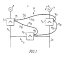
- Figure 1 illustrates a double-ended switchboard 1 in an electric power distribution system 3.
- Such an arrangement includes a split main bus 5 having a first side 5 1 which is connected through a first main circuit breaker 7 1 to a first source 9.
- the other half 5 2 of the split main bus 5 is connected through a second main circuit breaker 7 2 to a second source 11.
- a tie circuit breaker 7 3 interconnects the two halves 5 1 and 5 2 of the split main breaker 5.
- either source 9 or 11 can energize the entire split bus, or the source 9 can energize the left slide 5 1 of the main bus while the source 11 energizes the right side 5 2 .
- the interlocked tie circuit breaker 7 3 prevents interconnection of the two sources.
- the tie circuit breaker 7 3 should be open. If either of the main breakers 7 1 or 7 2 is open, the tie breaker 7 3 can be closed so that the other source supplies the entire split main bus 5. The latter situation could occur, for instance, if one of the sources and/or its main breaker failed or was taken out of service. As will be appreciated then, only two out of the three circuit breakers 7 1 -7 3 can be closed at any one time. The interlock system 13 of the invention insures this functionality.
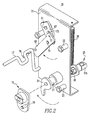
- the circuit breakers 7 1 -7 3 are power breakers of the type which have a pole shaft (not shown) which rotates with the opening and closing of the circuit breaker. Referring to Figure 2, a state indicator 15 mounted on the end of the pole shaft rotates with the shaft to provide an output indicating the open/closed state of the circuit breaker.
- Each circuit breaker 7 1 -7 3 also has an input in the form of an auxiliary trip bar 17 which when rotated holds the circuit breaker in the tripped or open position.
- the interlock system 13 interconnects the state indicator (output) 15 on each of the breakers with the auxiliary trip bar (input) 17 on each of the other breakers.
- This interlock system 13 includes an interlock unit 19 mounted on each circuit breaker over the state indicator and auxiliary trip bar.
- the interlock unit 19 includes a support plate 21 mounted on the side of the circuit breaker over the state indicator 15 and auxiliary trip bar 17 by standoffs 23.
- a mechanical drive coupling 25 is coupled to the state indicator 15.
- the drive coupling 25 includes a shaft 27 journalled in a bearing 29 mounted to the support plate 21.
- a follower 31 mounted on one end of the shaft 27 is engaged by a drive pin 33 on the state indicator 15.
- a lever arm 35 is mounted on the opposite end of the shaft 27. At each end of the lever arm 35 is a swivel coupling 37a and 37b.
- the state indicator When the associated circuit breaker 7 is closed, the state indicator is rotated clockwise as viewed in Figure 2 which in turn rotates the lever arm 35 counterclockwise as viewed in Figure 3 to raise the swivel 37a and at the same time lower the swivel 37b.
- a tension spring 38 maintains the lever arm 35 in an unactuated position.
- the output of the circuit breaker is applied as an input to the shaft 27 to provide two mechanical outputs which are the opposite motions of the two swivels 37.
- the interlock unit 19 also includes a mechanical AND gate 39.
- the AND gate 39 includes a pivot plate 41 with an elongated slot 43.
- a first input coupling in the form of a swivel 45a is pivotally mounted to the pivot plate 41 on a first side of the slot 43 by bearing 47a and is retained in place by a snap ring 49a.
- a second input coupling in the form of swivel 45b is similarly secured to the pivot plate 41 but on the other or second side of the slot 43 by bearing 47b and is likewise retained in place by a snap ring (not visible).
- An output shaft 51 extends toward and is aligned with the slot 43 in the pivot plate 41.
- An output coupling 53 is mounted on the output shaft 51 and engages the elongated slot 43.
- This output coupling 53 includes a coupling arm 55 mounted transversely on the end of the output shaft 51.
- a pair of shouldered pins 57 are fixed to the ends of the coupling arm 55.
- the pins 57 extend through the slot 43 in the pivot plate 41 which is retained in place by washers 59 and snap rings 61 engaging the ends of the pins.
- the lever arm 55 is rotationally locked to the output shaft 51 by a keyed opening 62 and secured thereto by a nut 63.
- the output coupling 53 provides a connection between the pivot plate 41 and the output shaft 51 which is offset radially from the axis of the shaft.
- the output shaft 51 is rotationally mounted on the support plate 21 by a bearing 65.
- a mechanical input to both of the input couplings or swivels 45a and 45b results in a counterclockwise rotation of the output shaft 51 as viewed in Figure 3.
- This results in clockwise rotation of a reversing cam 67 mounted on the output shaft 51 on the other side of the support plate 21.
- the reversing cam 67 is coupled to an actuating member 69, pivotally mounted on the support plate 21 by a pin 71, through a drive pin and bearing 73 on the actuating member 69 which engages a drive slot 75 in the reversing cam.
- the actuating member 69 has a flange 76 on its free end which engages the auxiliary trip bar 17 of the associated circuit breaker.
- the interlock units 19 1 -19 3 on the respective circuit breakers 7 1 -7 3 are interconnected by elongated actuators 77 12 -77 23 .
- these elongated actuators are push pull cables; however, rods or tension cables could also be used, depending upon the physical arrangement of the circuit breakers.
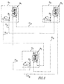
- the cables 77 provide an output from the drive coupling 25 of the interlock unit on each circuit breaker to an input coupling 45 of the AND gate 39 on each of the other circuit breakers.
- the cables are identified with subscripts indicating the circuit breaker which generates the output and the circuit breaker to which that output is applied.
- cable 77 12 connects the drive coupling 25 1 associated with the circuit breaker 7 1 to an input on the input coupling of the AND gate 39 2 on the circuit breaker 7 2 .
- the interconnections of the cables is shown schematically in Figure 6.
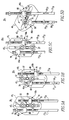
- Figure 5a illustrates the initial condition of the AND gate 39 1 in which both of the linked circuit breakers 7 2 and 7 3 are open. Under these conditions, the slot 43 1 in the pivot plate 41 1 is vertical. Without a biasing spring the location of the output shaft 51 1 and the pins 57 of the output coupling 53 1 are indeterminate, but for purposes of explanation they are shown approximately midway in the elongated slot 43 1 .
- the swivels forming the input couplings 45a and 45b allow for lost motion during the first portion of travel of the elongated actuators 77, but couple movement of the elongated actuators to the pivot plate 41 1 when an abutment surface formed by the lateral surface 78 on a nut forming an end effector 79 engage the swivel ring 80 of the swivel 45.
- each of the actuators are illustrated with clearance between the respective swivels 45 and the end effectors 79.
- a tension spring 83 returns the pivot plate 41 1 to the vertical position.
- the vertical position of the pivot plate will depend upon which one of the actuators is returned to off first. With the rotation of the pivot plate 41 1 back to the vertical position, the output shaft is returned to the off position.
- Other types of springs can be used to bias the pivot plate, such as a torsion spring.
- the lateral spacing of the swivels 45a and 45b on the pivot plate 41 1 are set to be compatible with the actuator stroke used by the drive couplings 25 which they can replace in this arrangement. For instance, where the swivels 37 on the drive couplings 25 are radially offset one inch from the shaft 27, a rotation of the lever arm 35 by the shaft 27 of about 60° will produce about a one-inch stroke. Because the pivot plate 41 1 of the AND gate 39 pivots about the fulcrum formed by the first elongated actuator to be moved to the ON position, the swivels 45a and 45b were positioned one-half inch laterally from the center of the elongated slot 43 to provide a pivot arm of one-inch. Thus, the one-inch stroke of the actuators produces a corresponding about 60° rotation of the output shaft 51 1 .
- elongated actuators are shown both extending in the same direction from the interlock units so that one is pushed and one is pulled during actuation, they could extend in opposite directions from the interlock unit so that either both are pulled or both are pushed for actuation. Of course, if tension members are used, they would both have to be pulled for actuation.
- the invention provides a simple, reliable, easily manufactured and economical mechanical AND gate which is especially useful for interlocking electric power switches. It also has the advantage of being compatible with and interchangeable with the mechanical OR gates disclosed in the co-pending US Application Serial No. 09/559,089, filed on April 27, 2000 and referenced above.
Landscapes
- Physics & Mathematics (AREA)
- Electromagnetism (AREA)
- Driving Mechanisms And Operating Circuits Of Arc-Extinguishing High-Tension Switches (AREA)
- Mechanisms For Operating Contacts (AREA)
- Supply And Distribution Of Alternating Current (AREA)
Abstract
Description
Claims (14)
- A mechanical AND gate (39) for interlocking multiple electric power switches (71-73), the mechanical AND gate (39) comprising:a pivot plate (41) having an elongated slot (43);a first input (45a) coupling mounted on the pivot plate (41) at a point laterally offset on a first side of the elongated slot (43);a second input coupling (45b) mounted on the pivot plate (41) at a point laterally offset on a second side of the elongated slot (43);an output shaft (51) extending transversely toward the pivot plate (41) and aligned with the elongated slot (43);an output coupling (53) mounted on but radially offset from an axis of the output shaft (51) and engaging and slideable relative to the pivot plate (41) in the elongated slot (43);a first elongated actuator (7721) engaging the first input coupling (45a) and axially moveable between an ON position and an OFF position;a second elongated actuator (7731) engaging the second input coupling (45b) and axially moveable between an ON and an OFF position; andthe first and second input couplings (45a,45b) being structured to only transfer force from the first and second elongated actuators (7721, 7731), respectively, to the pivot plate (41) with movement of the first and second elongated actuators (7721,7731), respectively, to the ON position, so that the pivot plate (41) slides relative to the output coupling (53) engaging the elongated slot (43) when only one of the first and second elongated actuator (7721,7731) moves to the ON position, and the pivot plate (41) rotates to rotate the output coupling (53) and therefore the output shaft (51), only when both the first and second elongated actuators (7721,7731) are moved to the ON position.
- The mechanical AND gate (39) of claim 1 wherein said first and second elongated actuators (7721,7731) are positioned to move along substantially parallel strokes (8121,8131) in opposite directions from the OFF to ON positions and the pivot plate (41) has an OFF position in which the elongated slot (43) is substantially parallel to the strokes of the first and second elongated actuators (7721,7731).
- The mechanical AND gate (39) of claim 2 wherein the first and second input couplings (45a,45b) are structured and positioned to provide lost motion between either of the first and second elongated actuators (7721,7731), respectively, and the pivot plate (41) when the other of the first and second elongated actuators (7721,7731) moves to the ON position and translates the pivot plate (41), the lost motion being taken up as the other of the first and second elongated actuators (7721,7731) reaches its ON position.
- The mechanical AND gate (39) of claim 3 wherein the first and second input couplings (45a,45b) are slip couplings comprising a coupling element which slides relative to the elongated actuator (7721,7731) to provide the lost motion, and which engages an abutment surface (78) on the elongated actuator (7721,7731) to couple the elongated actuator to the pivot plate (41) when the lost motion is taken up.
- The mechanical AND gate (39) of claim 4 wherein the coupling element (45a,45b) is a swivel including a swivel ring (80) through which the elongated actuator (7721,7731) slides, and the abutment surface (78) is provided on the elongated actuator (7721,7731) by a laterally extending surface on an end effector (79) which engages the swivel ring (80).
- The mechanical AND gate (39) of claim 5 wherein the output coupling (53) comprises a coupling arm (55) extending transversely to the axis of the output shaft (51) and a pair of pins (57) on the coupling arm (55) with an axis extending parallel to and on opposite sides of the axis of the output shaft (51).
- The mechanical AND gate (39) of claim 4 wherein the coupling element (45a) is a swivel including a swivel ring (80) through which the elongated actuator (7721,7731) slides, and the abutment surface (78) is provided on the elongated actuator (7721,7731) by a laterally extending surface on an end effector (79) which engages the swivel ring (80).
- An electric power distribution system (3) comprising:three electric power switches (71-73) each having an open state and a closed state, an indicator (15) indicating the state that the electric power switch (71-73) is in, and an auxiliary trip input (17) which holds the electric power switch (71-73) in the open state when actuated: anda mechanical AND gate (39) associated with each electric power switch (71-73) and comprising:a pivot plate (41) having an elongated slot (43);a first input coupling (45a) mounted on the pivot plate (41) at a point laterally offset on a first side of the elongated slot (43);a second input coupling (45b) mounted on the pivot plate (41) at a point laterally offset on a second side of the elongated slot (43);an output shaft (51) coupled to the auxiliary trip input of the associated electric power switch (71-73) and rotatable to actuate the associated auxiliary trip input (17);an output coupling (53) mounted on but radially offset from an axis of the output shaft (51) and engaging and slideable relative to the pivot plate (41) in the elongated slot (43);a first elongated actuator (7712,7723,7731) engaging the first input coupling (45a) and coupled to the state indicator (15) of one of the other electric power switches (71-73), the first elongated actuator (7712,7723,7731) being axially moveable between an ON position and an OFF position of the other electric power switch; anda second elongated actuator (7713,7721,7732) engaging the second input coupling (45b) and coupled to the state indicator (15) of another of the electric power switches (71-73), the second elongated actuator (7713,7721,7732) being axially moveable between an ON position and an OFF position of the another electric power switch (71-73), the first and second input couplings (45a,45b) being structured to only transfer force from the first and second elongated actuator (7712-7732), respectively, to the pivot plate (41) when the state indicators (15) of both the one and the another of the other two electric power switches (71-73) are in the ON state, such that only two of the three electric power switches (71-73) can be in the ON state at the same time.
- The electric power distribution system (3) of claim 8 wherein said first and second elongated actuators (7712-7732) are positioned to move along substantially parallel strokes (81) in opposite directions from the OFF to ON positions and the pivot plate (41) has an OFF position in which the elongated slot (43) is substantially parallel to the strokes (81) of the first and second elongated actuators (7712-7732).
- The electric power distribution system (3) of claim 9 wherein the first and second input couplings (45a,45b) are structured and positioned to provide lost motion between either the first and second elongated actuator (71-73), respectively, and the pivot plate (41) when the other of the first and second elongated actuators (7712-7732) moves to the ON position and translates the pivot plate (41), the lost motion being taken up as the other of the first and second elongated actuators (7712-7732) reaches its ON position.
- The electric power distribution system (3) of claim 10 wherein the first and second input couplings (45a,45b) are slip couplings comprising a coupling element which slides relative to the elongated actuator (7712-7732) to provide the lost motion, and which engages an abutment surface (78) on the elongated actuator (7712-7732) to couple the elongated actuator to the pivot plate (41) when the lost motion is taken up.
- The electric power distribution system (3) of claim 11 wherein the coupling element (45a,45b) is a swivel including a swivel ring (80) through which the elongated actuator (7712-7732) slides, and the abutment surface (78) is provided on the elongated actuator (7712-7732) by a laterally extending surface on an end effector (79) which engages the swivel ring (80).
- The electric power distribution system (3) of claim 12 wherein the output coupling (53) comprises a coupling arm (55) extending transversely to an axis of the output shaft (51) and a pair of pins (57) on the coupling arm (55) with an axis extending parallel to and on opposite sides of the axis of the output shaft (51).
- The electric power distribution system (3) of claim 11 wherein the coupling element (45a,45b) is a swivel including a swivel ring (80) through which the elongated actuator (7712-7732) slides, and the abutment surface (78) provided on the elongated actuator (7712-7732) by a laterally extending surface on an end effector (79) which engages the swivel ring (80).
Applications Claiming Priority (2)
| Application Number | Priority Date | Filing Date | Title |
|---|---|---|---|
| US705548 | 2000-11-03 | ||
| US09/705,548 US6388214B1 (en) | 2000-11-03 | 2000-11-03 | Mechanical and gate for interlocking electric power switches and distribution system incorporating same |
Publications (2)
| Publication Number | Publication Date |
|---|---|
| EP1204127A2 true EP1204127A2 (en) | 2002-05-08 |
| EP1204127A3 EP1204127A3 (en) | 2004-11-24 |
Family
ID=24833968
Family Applications (1)
| Application Number | Title | Priority Date | Filing Date |
|---|---|---|---|
| EP01126251A Withdrawn EP1204127A3 (en) | 2000-11-03 | 2001-11-05 | Mechanical and gate for interlocking electric power switches and distibution system incorporating same |
Country Status (6)
| Country | Link |
|---|---|
| US (1) | US6388214B1 (en) |
| EP (1) | EP1204127A3 (en) |
| AU (1) | AU776940B2 (en) |
| BR (1) | BR0105715A (en) |
| CA (1) | CA2360905C (en) |
| MX (1) | MXPA01011140A (en) |
Cited By (4)
| Publication number | Priority date | Publication date | Assignee | Title |
|---|---|---|---|---|
| WO2008006296A1 (en) | 2006-07-03 | 2008-01-17 | Zhejiang Chint Electrics Co., Ltd | Circuit breaker assembly with interlocking device |
| DE102008007987B3 (en) * | 2008-02-07 | 2009-05-07 | Moeller Gmbh | Arrangement for locking switches |
| CN102820149A (en) * | 2012-08-21 | 2012-12-12 | 浙江天正电气股份有限公司 | Spring force differential interlocking device among three circuit breakers |
| EP3389066A1 (en) * | 2017-04-11 | 2018-10-17 | LSIS Co., Ltd. | Interlock apparatus of circuit breaker |
Families Citing this family (9)
| Publication number | Priority date | Publication date | Assignee | Title |
|---|---|---|---|---|
| US6617533B1 (en) * | 2002-09-20 | 2003-09-09 | Siemens Energy & Automation, Inc. | Interlock for a circuit breaker |
| US7053321B2 (en) * | 2003-04-10 | 2006-05-30 | Eaton Corporation | Apparatus operating an isolation switch in coordination with a circuit breaker |
| US7019229B1 (en) * | 2004-09-03 | 2006-03-28 | Eaton Corporation | Door interlock assembly and draw-out circuit breaker assembly employing the same |
| US6995327B1 (en) | 2005-04-11 | 2006-02-07 | Eaton Corporation | Four-way interlock system and bypass transfer switch employing the same |
| CN101989505B (en) * | 2009-07-29 | 2013-10-23 | 西门子公司 | Interlocking module and interlocking device composed of it |
| WO2012117270A1 (en) | 2011-03-01 | 2012-09-07 | Larsen & Toubro Limited | An improved interlock system for switching devices |
| CN106206121B (en) * | 2016-09-07 | 2018-09-04 | 上海电科电器科技有限公司 | The transfer switching equipment of interlocking |
| US11450490B2 (en) | 2019-03-08 | 2022-09-20 | Eaton Intelligent Power Limited | Mechanical interlock assemblies for panelboards and related systems and methods |
| CN112447426B (en) * | 2019-09-04 | 2024-08-13 | Abb瑞士股份有限公司 | Mechanical interlocking device and dual-power supply system |
Family Cites Families (10)
| Publication number | Priority date | Publication date | Assignee | Title |
|---|---|---|---|---|
| US4286242A (en) | 1979-09-17 | 1981-08-25 | Westinghouse Electric Corp. | Mechanical interlock for low voltage circuit breakers |
| US5023469A (en) | 1990-02-05 | 1991-06-11 | Zenith Controls, Inc. | Interlock system for bypass/isolation automatic transfer switch |
| US5581133A (en) | 1993-12-17 | 1996-12-03 | Eaton Corporation | Combination transfer and bypass isolation switch utilizing drawout protective devices and key interlocks |
| US5436415A (en) | 1994-07-19 | 1995-07-25 | Eaton Corporation | Interlock for electrical switches |
| DE4439746C1 (en) * | 1994-10-31 | 1996-04-04 | Siemens Ag | Evaluation device for a system for interlocking circuit breakers |
| DE19508808C1 (en) * | 1995-03-06 | 1996-09-19 | Siemens Ag | Mechanical AND gate for mutual interlocking of circuit breakers |
| IT1289481B1 (en) * | 1996-12-20 | 1998-10-15 | Sace Spa | SERIES OF SWITCHES WITH MUTUAL LOCKING MEANS |
| US5914467A (en) | 1997-08-11 | 1999-06-22 | Generac Power Systems, Inc. | Automatic transfer switch with improved positioning mechanism |
| US5902974A (en) * | 1997-12-29 | 1999-05-11 | Eaton Corporation | Slide bar interlock |
| US5929405A (en) | 1998-05-07 | 1999-07-27 | Eaton Corporation | Interlock for electrical switching apparatus with stored energy closing |
-
2000
- 2000-11-03 US US09/705,548 patent/US6388214B1/en not_active Expired - Lifetime
-
2001
- 2001-10-30 AU AU87247/01A patent/AU776940B2/en not_active Ceased
- 2001-11-01 BR BR0105715-4A patent/BR0105715A/en not_active Application Discontinuation
- 2001-11-01 CA CA2360905A patent/CA2360905C/en not_active Expired - Lifetime
- 2001-11-01 MX MXPA01011140A patent/MXPA01011140A/en active IP Right Grant
- 2001-11-05 EP EP01126251A patent/EP1204127A3/en not_active Withdrawn
Cited By (12)
| Publication number | Priority date | Publication date | Assignee | Title |
|---|---|---|---|---|
| WO2008006296A1 (en) | 2006-07-03 | 2008-01-17 | Zhejiang Chint Electrics Co., Ltd | Circuit breaker assembly with interlocking device |
| EP2040277A4 (en) * | 2006-07-03 | 2010-09-22 | Zhejiang Chint Electrics Co Lt | SHORT-CIRCUIT ASSEMBLY WITH INITIATION DEVICE |
| US8237070B2 (en) | 2006-07-03 | 2012-08-07 | Zhejiang Chint Electrics Co., Ltd. | Set of circuit breakers with interlock means |
| DE102008007987B3 (en) * | 2008-02-07 | 2009-05-07 | Moeller Gmbh | Arrangement for locking switches |
| WO2009097964A1 (en) * | 2008-02-07 | 2009-08-13 | Moeller Gmbh | Apparatus for locking of shifters |
| CN101939807B (en) * | 2008-02-07 | 2013-12-25 | 伊顿工业有限公司 | Apparatus for locking of switches |
| US8692143B2 (en) | 2008-02-07 | 2014-04-08 | Eaton Industries Gmbh | Cable interlock between power switches |
| CN102820149A (en) * | 2012-08-21 | 2012-12-12 | 浙江天正电气股份有限公司 | Spring force differential interlocking device among three circuit breakers |
| CN102820149B (en) * | 2012-08-21 | 2015-04-08 | 浙江天正电气股份有限公司 | Spring force differential interlocking device among three circuit breakers |
| EP3389066A1 (en) * | 2017-04-11 | 2018-10-17 | LSIS Co., Ltd. | Interlock apparatus of circuit breaker |
| CN108695086A (en) * | 2017-04-11 | 2018-10-23 | Ls产电株式会社 | The linkage of breaker |
| US10614973B2 (en) | 2017-04-11 | 2020-04-07 | Lsis Co., Ltd. | Interlock apparatus for three circuit breakers |
Also Published As
| Publication number | Publication date |
|---|---|
| AU776940B2 (en) | 2004-09-30 |
| CA2360905C (en) | 2010-09-14 |
| AU8724701A (en) | 2002-05-09 |
| CA2360905A1 (en) | 2002-05-03 |
| MXPA01011140A (en) | 2004-05-21 |
| US6388214B1 (en) | 2002-05-14 |
| BR0105715A (en) | 2002-07-02 |
| EP1204127A3 (en) | 2004-11-24 |
Similar Documents
| Publication | Publication Date | Title |
|---|---|---|
| CA2360905C (en) | Mechanical and gate for interlocking electric power switches and distribution system incorporating same | |
| EP1150316B1 (en) | Mechanical interlock with overtravel compensation for coordinating operation of circuit breakers | |
| US8138861B2 (en) | Inertial catch for an automatic transfer switch power contractor | |
| US5436415A (en) | Interlock for electrical switches | |
| US6995327B1 (en) | Four-way interlock system and bypass transfer switch employing the same | |
| EP0890181B1 (en) | Cable interlock system for circuit breakers | |
| EP2040277B1 (en) | Circuit breaker assembly with interlocking device | |
| US9685283B2 (en) | Interlock for circuit interrupting device | |
| WO2012059811A1 (en) | An improved mechanical interlock, dual toggling and three position mechanism of an electrical load break switch | |
| CN102598178B (en) | For the drive unit of multi-position switch equipment | |
| CN1892955B (en) | Opening/closing device of an electric switchgear | |
| EP2549499B1 (en) | Electrical switching apparatus and secondary trip mechanism therefor | |
| US8389884B2 (en) | Electrical switch apparatus having two interrupters, such as a busbar disconnector and a grounding disconnector, and including common actuator means for the movable contacts of the interrupters | |
| CN101283426B (en) | Form-fit locking device preventing switching on | |
| CN101118821A (en) | Switching device with operating element | |
| KR102222142B1 (en) | Switchgear interlock device and opening/closing system | |
| US20240071698A1 (en) | Switch for a Medium Voltage or High Voltage Switchgear | |
| US7091432B2 (en) | Power circuit breaker | |
| CN108447710B (en) | Mechanical rapid energy storage system | |
| CA2345174C (en) | Mechanical interlock with overtravel compensation for coordinating operation of circuit breakers | |
| HK1120925B (en) | Interlocking lock in order to prevent a switch from being switched on | |
| HK1171285B (en) | Drive device, for a multi-position switching apparatus |
Legal Events
| Date | Code | Title | Description |
|---|---|---|---|
| PUAI | Public reference made under article 153(3) epc to a published international application that has entered the european phase |
Free format text: ORIGINAL CODE: 0009012 |
|
| AK | Designated contracting states |
Kind code of ref document: A2 Designated state(s): AT BE CH CY DE DK ES FI FR GB GR IE IT LI LU MC NL PT SE TR |
|
| AX | Request for extension of the european patent |
Free format text: AL;LT;LV;MK;RO;SI |
|
| PUAL | Search report despatched |
Free format text: ORIGINAL CODE: 0009013 |
|
| AK | Designated contracting states |
Kind code of ref document: A3 Designated state(s): AT BE CH CY DE DK ES FI FR GB GR IE IT LI LU MC NL PT SE TR |
|
| AX | Request for extension of the european patent |
Extension state: AL LT LV MK RO SI |
|
| AKX | Designation fees paid | ||
| REG | Reference to a national code |
Ref country code: DE Ref legal event code: 8566 |
|
| STAA | Information on the status of an ep patent application or granted ep patent |
Free format text: STATUS: THE APPLICATION IS DEEMED TO BE WITHDRAWN |
|
| 18D | Application deemed to be withdrawn |
Effective date: 20050202 |