Background of the Invention
1. Field of the Invention
The present invention relates to an optical
information recording medium on and from which
information can be recorded and replayed through
irradiation of a laser beam, a method of recording
information on the same and a method of manufacturing
the same. More particularly, the present invention
relates to a write once type optical information
recording medium on which information can be recorded
only once, a method of recording information on the
same, and a method of manufacturing the same.
2. Description of the Related Art
With spreading of CD-ROM and DVD-ROM in
recent years, an optical information recording medium
called CD-R or DVD-R on which information can be
recorded only once comes rapidly into wide use. In
CD-R and DVD-R, a photosensitive pigment layer as a
record layer is formed on a substrate by a spin
coating method or a vaporizing method. A reflection
layer of Al or Au is formed on the pigment layer to
make the reflectivity equal to that of the CD-ROM.
Pigment material is selected in such a manner that the
absorption of a laser beam is present to the extent
that information can be recorded, in the wavelength of
the semiconductor laser (hereinafter, to be simply
referred to as LD), which is used for the record and
replay of the optical information. The wavelength of
the semiconductor laser beam used for the record and
replay of the information is about 780 nm in CD-R and
also is about 650 nm in DVD-R.
On the other hand, in recent years, the
research and development of a semiconductor laser for
a blue-purple laser beam are developing rapidly. By
this, the coming to practical use of the blue-purple
semiconductor laser with the wavelength of 380 to 430
nm is approaching. The record density of the optical
disk is mainly decided based on a spot size of the
laser beam which is used for the record and replay of
the information. The spot size is proportional to the
wavelength of the semiconductor laser. Therefore, it
is expected that the record capacity of the optical
disk greatly increases by using a blue-purple
semiconductor laser with a short wavelength, compared
with that of the red semiconductor laser which has
come into practical use.
However, heretofore, any pigment material on
which information can be recorded with the laser beam
with the wavelength of 380 to 430 nm does not have
found. For this reason, an optical information
recording medium for the blue-purple semiconductor
laser does not come into practical use. Also, the
above manufacturing process is complicated in which
the reflection layer is formed by the sputtering
method after a pigment material layer is formed by the
spin coating method. The manufacturing process would
lead the increase of manufacturing cost of the optical
information recording medium.
In conjunction with the above description, an
optical recording medium is disclosed in Japanese Laid
Open Patent application (JP-A-Heisei 10-172180). In
this reference, the record and erasure of information
are carried out by the phase change between an
amorphous phase and a crystal phase through the
irradiation of light. A first dielectric layer, a
record layer, a second dielectric layer, a reflection
layer are laminated on a transparent substrate in this
order at least. The wavelength of the irradiated
light is equal to or less than 550 nm, and the
refraction index n in the first dielectric layer in
the wavelength of the irradiated light is in a range
of 1.4 to 2.1. The wavelength of the irradiated light
is equal to or less than 450 nm and the refraction
index n in the first dielectric layer in the
wavelength of the irradiated light is in a range of
1.4 to 1.8.
Also, an optical recording medium is
disclosed in Japanese Laid Open Patent application
(JP-A-Heisei 10-208296). In this reference, the
optical recording medium has an optical record layer
which contains Te on a substrate at least. An
attenuation coefficient ka in an amorphous layer of
the optical record layer is equal to or less than 2.5
in the wavelength of 400 to 500 nm. Also, the optical
record layer contains the hydrogen from 30 ppm to
10000 ppm.
Also, an optical recording medium is
disclosed in Japanese Laid Open Patent application
(JP-A-Heisei 11-39709). In this reference, the record
and erasure of information are carried out by the
phase change between an amorphous phase and a crystal
phase through the irradiation of light. A first
dielectric layer, a lower dielectric layer, a record
layer, a second dielectric layer, a reflection layer
are laminated on the transparent substrate in this
order at least. It has the relation that the
refraction index and attenuation coefficient of each
layer and the thickness of the layer has the following
relations in the wavelength of 700 630 nm and the
wavelength of 500 380 nm.
1.85 ≦ na ≦ 2
45 ≦ da ≦ 55 (nm)
2.1 ≦ nb
145 ≦ db ≦ 155 (nm)
2.4 ≦ nα ≦ 4.5
1.9 ≦ kα ≦ 2.9
1.65 ≦ nc ≦ 4.5
3.2 ≦ kc ≦ 4.1
0 < d r≦ 20 (nm)
2.1 ≦ nd ≦ 2.4
10 ≦ dd ≦ 20 (nm)
0.4 ≦ ne ≦ 1.4
3.8 ≦ ke ≦ 6.2
where na is a refraction index of the first dielectric
layer, da is the thickness of the first dielectric
layer (nm), nb is a refraction index of the lower
dielectric layer, db is the thickness of the lower
dielectric layer (nm), nα is the refraction index of
the amorphous condition of the record layer, kα is
the attenuation coefficient of the amorphous condition
of the record layer, nc is the refraction index of the
crystal condition of the record layer, kc is the
attenuation coefficient of the crystal condition of
the record layer, dr is the thickness of the record
layer (nm), nd is the refraction index of the second
dielectric layer, dd is the thickness of the second
dielectric layer (nm), ne is the refraction index of
the reflection layer, and ke is an attenuation
coefficient of the reflection layer.
Also, an optical recording medium is
disclosed in Japanese Laid Open Patent application
(JP-A-Heisei 11-39716). In this reference, the record
and erasure of information are carried out by the
phase change between the amorphous phase and the
crystal phase through the irradiation of light. A
first dielectric layer, a record layer, a second
dielectric layer, a reflection layer are laminated on
the transparent substrate in this order at least. The
refraction index and attenuation coefficient of each
layer and the thickness of the layer have the
following relations in the wavelength from 390 nm to
450.
2.2 ≦ na ≦ 2.3
30 ≦ da ≦ 500
2.58 ≦ nα ≦ 3.3
2.6 ≦ kα ≦ 2.9
1.77 ≦ nc ≦ 2.5
3.2 ≦ kc ≦ 3.8
7 ≦ dr ≦ 35 (nm)
2.25 ≦ nb ≦ 2.4
0 < db ≦ 25( nm)
0.4 ≦ nβ ≦ 0.6
3.8 ≦ kβ ≦ 4.25
where na is the refraction index of the first
dielectric layer, da is the thickness of the first
dielectric layer (nm), nα is the refraction index of
the amorphous condition of the record layer, kα is
the attenuation coefficient of the amorphous condition
of the record layer, nc is the refraction index of the
crystal condition of the record layer, kc is the
attenuation coefficient of the crystal condition of
the record layer, dr is the thickness of the record
layer (nm), nb is the refraction index of the second
dielectric layer, db is the thickness of the second
dielectric layer (nm), nβ is the refraction index of
the reflection layer, and kβ shows an attenuation
coefficient in the reflection layer.
Also, a phase change-type optical recording
medium is disclosed in Japanese Laid Open Patent
application (JP-A-Heisei 11-265525). In this
reference, the phase change-type optical recording
medium has a substrate, a record layer and a
dielectric layer formed between the substrate and the
record layer at least. The record layer is formed on
one of the surfaces of the substrate and a phase
change between the crystal state and the amorphous
state is reversibly accomplished according to the
strength of irradiation light. The dielectric layer
is formed between the record layer and the substrate.
Overwrite is carried out with the single laser beam
modulated in strength having the wavelength from 400
nm to 500 nm. The dielectric layer consists of the
mixture of ZnS and SiO2 and the record layer consists
of the material which contains Ge, Te and Sb at least.
Between the substrate and the dielectric layer, a
multiple reflection layer is provided which consists
of Ag, TiO2, the mixture of Ag and TiO2, the mixture
which contains Ag as the main component or the mixture
which contains TiO2 as the main component. A
reflection layer is provided for the surface of the
substrate opposite to that on the side of the record
layer and a second dielectric layer is provided
between the reflection layer and the record layer.
Summary of the Invention
An object of the present invention is to
provide an optical information recording medium which
can be formed in a simple manufacture process, and in
which it is possible to record only once using a
semiconductor laser with the wavelength of 380 to 430
nm, a method manufacturing the same, and a recording
method on the same.
In an aspect of the present invention, an
optical information recording medium includes a
substrate, and a record layer formed on the substrate.
Information is recorded using a laser beam with a
wavelength of 380 nm to 430 nm, and refraction index n
and attenuation coefficient k of the record layer
satisfy a relation of 3.9 < n < 5.6 and k > 0.4 to the
wavelength of 380 to 430 nm.
Here, the optical information recording
medium has a first reflectivity before the record of
the information and has a second reflectivity after
the record of the information. It is desirable that
the second reflectivity is higher than the first
reflectivity, and the optical information recording
medium has compatibility with a replay only type
optical information recording medium in reflectivity.
In this case, it is desirable that the reflectivity of
the record layer before the record of the information
is in a range of 30 to 70%.
Also, it is desirable that the film thickness
of the record layer is in range of 10 nm to 30 nm.
Also, it is desirable that thermal
conductivity of the record layer is in a range of 0.5
W/mK to 20 W/mK.
Also, the record layer may have a layer
containing at least one selected from the group
consisting of Si, Ge, Si oxide, Si nitride, Ge oxide
and Ge nitride.
In another aspect of the present invention,
an optical information recording medium includes a
substrate, and a record layer formed on the substrate.
Information is recorded using a laser beam with a
wavelength of 380 nm to 430 nm, and absorptivity of
the record layer is equal to or more than 20% to the
laser beam of the wavelength of 380 to 430 nm.
Here, the optical information recording
medium has a first reflectivity before the record of
the information and has a second reflectivity after
the record of the information. It is desirable that
the second reflectivity is higher than the first
reflectivity, and the optical information recording
medium has compatibility with a replay only type
optical information recording medium in reflectivity.
In this case, it is desirable that the reflectivity of
the record layer before the record of the information
is in a range of 30 to 70%.
Also, it is desirable that the film thickness
of the record layer is in range of 10 nm to 30 nm.
Also, it is desirable that thermal
conductivity of the record layer is in a range of 0.5
W/mK to 20 W/mK.
Also, the record layer may have a layer
containing at least one selected from the group
consisting of Si, Ge, Si oxide, Si nitride, Ge oxide
and Ge nitride.
In still another aspect of the present
invention, a method of recording information on an
optical information recording medium, includes the
steps of:
where Pw is a peak power of the multi-pulse, Pbw is a
bottom power of the multi-pulse, and Pb is a bias
power between the record pulses.
Here, when the optical information recording
medium further includes guide trenches formed on the
substrate in a predetermined pitch, the information
may be recorded to a flat section between the guide
trenches.
In yet still another aspect of the present
invention, a method of recording information on an
optical information recording medium, includes the
steps of:
In further another aspect of the present
invention, a method of manufacturing an optical
information recording medium, on which optical
information is recorded using a laser beam with a
wavelength of 380 nm to 430 nm, includes the steps of:
In an aspect of the present invention, an
optical information recording medium includes a
substrate, a record layer formed on the substrate, a
light transmissive layer formed on the record layer,
and a thermal transformation restraint layer provided
between the record layer and the light transmissive
layer. Information is recorded using a laser beam
having a wavelength of 380 nm to 430 nm and irradiated
to the record layer through the light transmissive
layer.
Here, the thermal transformation restraint
layer may be formed of at least one layer selected the
group consisting of a SiN layer, a SiO2 layer, a Ta2O5
layer, an Al2O3 layer, an AlN layer, a SiC layer, and a
TiC layer.
Also, the thermal transformation restraint
layer is a metal layer which contains Au or Ag and
which has a film thickness of 5 nm to 15 nm.
Also, the record layer may be a Si layer or a
Ge layer.
In another aspect of the present invention, a
method of recording optical information on an optical
information recording medium, includes the steps of:
In another aspect of the present invention,
an optical information recording medium includes a
substrate having guide trenches formed on the
substrate in a predetermined pitch, and a record layer
formed on the substrate. Information is recorded a
flat section between the guide trenches using a laser
beam having a wavelength of 380 nm to 430 nm.
Here, the information may be recorded in each
of the guide trenches in addition to the flat section
between the guide trenches.
In another aspect of the present invention,
an optical information recording medium includes a
substrate having guide trenches formed on the
substrate in a predetermined pitch, and a record layer
formed on the substrate. When information is recorded
using a laser beam having a wavelength of 380 nm to
430 nm, a depth of the guide trench corresponding to a
portion where the information may be recorded is
shallower after the record than the depth of the guide
trench before the record.
Here, the optical information recording
medium has a first reflectivity before the record of
the information and has a second reflectivity after
the record of the information. It is desirable that
the second reflectivity is higher than the first
reflectivity.
Brief Description of the Drawings
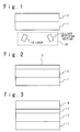
Fig. 1 is a cross sectional view showing the
structure of a phase change type optical information
recording medium of the present invention when a laser
beam is irradiated from the side of the substrate;
Fig. 2 is a cross sectional view showing the
structure of another phase change type optical
information recording medium of the present invention
when a laser beam is irradiated from the side of the
substrate;
Fig. 3 is a cross sectional view showing the
structure of another phase change type optical
information recording medium of the present invention
when a laser beam is irradiated from the side of the
substrate;
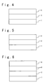
Fig. 4 is a cross sectional view showing the
structure of another phase change type optical
information recording medium of the present invention
when a laser beam is irradiated from the side of the
substrate;
Fig. 5 is a cross sectional view showing the
structure of another phase change type optical
information recording medium of the present invention
when a laser beam is irradiated from the side of the
substrate;
Fig. 6 is a cross sectional view showing the
structure of another phase change type optical
information recording medium of the present invention
when a laser beam is irradiated from the side of the
substrate;
Fig. 7 is a cross sectional view showing the
structure of another phase change type optical
information recording medium of the present invention
when a laser beam is irradiated from the side of the
substrate;
Fig. 8 is a cross sectional view showing the
structure of a phase change type optical information
recording medium of the present invention when a laser
beam is irradiated from the side of the light
transmissive layer;
Fig. 9 is a cross sectional view showing the
structure of another phase change type optical
information recording medium of the present invention
when a laser beam is irradiated from the side of the
light transmissive layer;
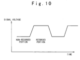
Fig. 10 is a schematic diagram showing a
replay signal waveform from the optical information
recording medium of the present invention;
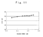
Fig. 11 is a diagram showing the relation
between record power and C/N ratio in the optical
information recording medium according to the first
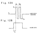
embodiment of the present invention;
Figs. 12A and 12B are diagrams showing a
laser drive waveform and record data to the optical
information recording medium according to the first
embodiment of the present invention;
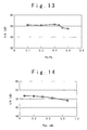
Fig. 13 is a diagram showing the relation
between Pb/Pw ratio and C/N ratio in the optical
information recording medium according to a fourth
embodiment of the present invention;
Fig. 14 is a diagram showing the relation
between Pbw and C/N ratio in the optical information
recording medium according to a fifth embodiment of
the present invention; and
Fig. 15 is a diagram showing the relation
between record power and C/N ratio in the optical
information recording medium according to an eleventh
embodiment of the present invention.
Description of the Preferred Embodiments
Next, an optical information recording medium
of the present invention will be described below in
detail with reference to the attached drawings. Figs.
1 to 7 are cross sectional views showing the structure
of a phase change type optical disk as the optical
information recording medium of the present invention.
Fig. 10 is a diagram showing a replay signal waveform
schematically.
In the optical information recording medium
of the present invention shown in Fig. 1, the simple
structure is adopted in which a record layer 2 is
formed on a substrate 1. The record layer 2 may be a
single layer or a multiple layer. The thickness of
the substrate 1 is about 0.3 mm to 1.2 mm. As the
material of the substrate 1, the resin of
polycarbonate or glass is used. Generally, as shown
in Fig. 1, the record and replay of information are
carried out by inputting a laser beam from the laser
10 provided on the side of the substrate 1 and a
replay is carried out by receiving a reflection light
by a light receiving section 12.
The structure that the record layer 2 is
formed on the substrate 1 is the most desirable
because the structure is the simplest. However, in
the optical information recording medium of the
present invention shown in Fig. 2, the record layer 2
is formed on the substrate 1. To prevent from flaw
and refuse, ultraviolet ray hardening resin 3 may be
formed on the record layer 2. Moreover, as shown in
Fig. 3, another substrate 4 may be adhered or attached
to the ultraviolet ray hardening resin 3 because of
the mechanical characteristic improvement.
Besides, in the optical information recording
medium of the present invention shown in Figs. 4 and 5,
the record layer 2 is formed on the substrate 1 and a
dielectric layer 5 or a reflection layer 6 may be
laminated on the record layer 2. Or, as shown in Fig.
6, a reflection layer 6 may be laminated on a
dielectric layer 5. Moreover, as shown in Fig. 7,
another substrate 4 may be further adhered to the
dielectric layer 5 or the reflection layer 6 by
ultraviolet rays hardening resin 3 because of the
mechanical characteristic improvement.
Also, as shown in Fig. 8, in the optical
information recording medium of the present invention,
the record layer 2 is formed on the substrate 1 and a
light transmissive layer 7 with the thickness of about
0.1 mm is formed on the record layer 2. The thickness
of the substrate 1 is about 0.3 mm to 1.2 mm and the
resin of polycarbonate or glass is used as the
material of the substrate 1. Also, as shown in Fig. 9,
a thermal transformation restraint layer 8 may be
provided between the record layer 2 and the light
transmissive layer 7. In case of such a structure, as
shown in Fig. 8, the record and replay of information
are carried out by inputting the laser beam from the
laser 10 arranged on the side of light transmissive
layer 7 and the replay is carried out by receiving the
reflection light with a light receiving section 12.
The film thickness of the record layer 2 is
desirable to be from 10 nm to 30 nm. This is because
the film quality and environment endurance are
degraded in the film which is thinner than 10 nm so
that it is difficult to get sufficiently high
reflectivity. Also, because thermal capacity becomes
large in the film thickness equal to or more than 30
nm, the record sensitivity becomes low and it is not
able to carry out good record. Moreover, even if a
recording operation is carried out in high power in
the film thickness equal to or more than 30 nm, heat
interference between marks, i.e., the influence of the
temperature rise in a mark recorded immediately before
the mark which tries to be recorded is large so that
the good recording operation cannot be carried out.
Next, the optical characteristics of the
optical information recording media of Figs. 1 to 7
will be described. The reflectivity of the optical
information recording medium of the present invention
is designed to be 30% to 70% before the recording
operation. This is because the reflectivity of the
optical information recording medium of replay only
type (CD-ROM) is about 60% generally and the
compatibility with the CD-ROM is considered. If the
reflectivity of the optical information recording
medium is about a half of that of the CD-ROM, it is
possible to replay information from the optical
information recording medium of the present invention
by adding a simple AGC (auto gain control) circuit.
Moreover, in the optical information
recording medium of the present invention, because the
reflectivity becomes higher after the recording
operation as shown by the replay signal waveform shown
in Fig. 10, the compatibility with the CD-ROM can be
achieved easier. The reason why the reflectivity
becomes high after the recording operation is that the
surface portion of the substrate 1 fuses in the region
where a laser beam has been irradiated and flows out
from there into a guide trench (not shown). As a
result, the depth of the guide trench becomes
shallower than the depth before the recording
operation. In a conventional optical information
recording medium, the reflectivity decreases through
the recording operation so that a servo signal becomes
unstable. However, in the optical information
recording medium of the present invention, there is no
case that the servo signal becomes unstable, because
the reflectivity becomes higher after the recording
operation.
Also, it is possible to record information in
the guide trench and in the flat section (not shown)
between the guide trenches. However, when an optical
information recording medium is formed to have a
single record layer on the substrate, the power of the
laser beam can be made lower and the signal quality is
good, if the recording operation is carried out on the
flat section between the guide trenches. It should be
noted that the inventor of the present application
found the above facts.
The embodiments of the present invention will
be described more in detail. In the embodiment, a
light head 20 with a laser 10, a light receiving
section; and an object lens.
[Embodiment 1]
First, a method of manufacturing the optical
information recording medium according to the first
embodiment of the present invention and a method of
recording information on the optical information
recording medium will be described with reference to
Figs. 11 and 12A and 12B. Fig. 11 is a diagram
showing a relation between record power and C/N
(carrier-to-noise) ratio in the optical information
recording medium according to the first embodiment.
Figs. 12A and 12B show diagrams showing a laser drive
waveform and record data.
As shown in Fig. 3, a polycarbonate substrate
with the thickness of about 0.6 mm was used as the
substrate 1 of the optical information recording
medium. A Si layer was formed on the substrate 1 by a
sputtering method as the record layer 2 to have the
thickness of about 20 nm. Moreover, another
polycarbonate substrate 4 with the thickness of about
0.6 mm was adhered onto the recording layer 2 by
ultraviolet ray hardening resin layer 3 to secure
mechanical characteristics. Also, the substrate 1
having a guide trench with the depth of about 30 nm,
and the pitch of about 0.4 µm between the trenches
was used.
The reflectivity of the optical information
recording medium to the laser beam with the wavelength
of 400 nm was 44% before the recording operation, and
57% after the recording operation. The absorptivity
of the Si layer 2 to the laser beam was 43% before the
recording operation. Also, a set of n: refraction
index and k: attenuation coefficient was (4.4, 1.9) to
the wavelength of 400 nm, and the thermal conductivity
was 1.5 W/mK.
It should be noted that the reflectivity of
about 50% could be realized even if a dielectric layer
5 of ZnS-SiO2, SiN, AlN, SiO2, Al2O3, Ta2O5 was formed
on the Si layer 2 as shown in Fig. 4. Moreover, as
shown in Fig. 6, a metal reflection layer 6 may be
formed on the dielectric layer 5 to increase the
reflectivity. In the first embodiment, only the Si
layer was formed on the substrate 1.
A recording operation was carried out at the
record frequency of 5 MHz, while the optical
information recording medium was rotated in the line
velocity of 3 m/s. The relation between record power
of the laser beam and C/N ratio at that time was
measured. The light head 20 having an object lens of
NA = 0.65 and a laser with the wavelength of 400 nm
was used for the record and replay. The recording
operation was carried out on the flat section between
the guide trenches. The result is shown in Fig. 11.
As seen from Fig. 11, in the optical information
recording medium of the first embodiment, the high C/N
ratio of 50 dB or more is achieved when the record
power is more than 5 mW. It should be noted that
record power equal to or more than 6 mW is required
when the recording operation is carried out on the
inside of the guide trench, and also the C/N ratio of
about 43 dB can be only achieved.
Also, it should be noted that the recording
operation is carried out using a record pulse shown in
Figs. 12A and 12B. In Figs. 12A and 12B, Pw is a peak
power of the laser beam from the laser 10, Pbw is a
bottom power of the laser beam, and Pb is a bias power
between the record pulses. In the first embodiment,
Pbw = 0.1 mW, and Pb = 1.5 mW. Also, a record pulse
waveform to the 3T record data is shown in Figs. 12A
and 12B (the record frequency is 5 MHz and the clock
frequency is 30 MHz). The respective parameters are
set to Td = 1T, and Tw = Tbw = = 0.5T.
In this way, according to the optical
information recording medium in the first embodiment,
the record layer 2 is formed on the substrate 1 using
material which has a suitable absorptivity (equal to
or more than 20%) to the laser beam with the
wavelength of 380 to 430 nm from the laser 10 and the
low thermal conductivity. By this, it was found to be
possible to carry out the recording operation in the
high C/N ratio. It is not desirable that the
absorptivity of the record layer 2 is lower than 20%,
because the laser beam having very high record power
is required. It was found that it was sufficient to
form the record layer 2 on the substrate 1 and to use
material with the refraction index n and the
attenuation coefficient k satisfying 3.9 < n < 5.6 and
k > 0.4 for the record layer 2, in order to realize
the reflectivity equal to or more than 30%, and the
absorptivity equal to or more than 20% in the
wavelength of about 400 nm.
[Embodiment 2]
A disk was formed to have a Si layer, a Ge
layer, a (Si+N) layer or (Ge+N) layer formed by adding
a nitrogen gas to a sputtering gas as the record layer
2 using the substrate like the first embodiment. By
changing sputtering power and sputtering gas pressure
on the formation of the record layer 2, an optical
constant was changed.
A recording operation was carried out at the
record frequency of 5 MHz while the disk was rotated
in the line velocity of 3 m/s and then a C/N ratio was
measured. A
light head 20 with a laser of the
wavelength of 405 nm and an object lens of NA = 0.65
was used for the recording operation and replaying
operation. The record of information was carried out
on the flat section between the guide trenches. The
record pulse waveform was the same as in the first
embodiment. The result is shown in the following
table 1.
| record layer | optical constants (n, k) | film thickness (nm) | C/N ratio (dB) |
| Ge | (5.9,2.0) | 15 | 46 |
| Ge | (5.6,2.0) | 15 | 52 |
| Si | (4.0,1.5) | 25 | 51 |
| Si | (3.9,1.4) | 25 | 50.5 |
| Si | (3.6,1.3) | 25 | 46 |
| Si+N | (4.0,0.4) | 30 | 50 |
| SiN | (4.0,0.3) | 30 | 45 |
As understood from the table 1, the high C/N
ratio equal to or more than 50 dB is obtained in 3.9 <
n < 5.6 and k > 0.4. It should be noted that the
record could not done to the disk at all although the
record was tried using the light head 20 with a laser
of the wavelength of 660 nm and an object lens of NA =
0.65.
[Embodiment 3]
Next, a method of recording on the optical
information recording medium and a method of
manufacturing the optical information recording medium
according to the third embodiment of the present
invention will be described. In the third embodiment,
the experiment to optimize the absorptivity of the
record layer will be described.
A (Si+O) layer was formed on the
polycarbonate substrate with thickness of 1.1 mm by a
sputtering method as the
record layer 2 to have the
thickness of 15 nm, and a polycarbonate film with the
thickness of 0.1 mm was adhered onto the record layer
as a
light transmissive layer 7. In this way, the
optical information recording medium shown in Fig. 8
was produced. The absorptivity of the
record layer 2
was changed by changing an oxygen addition quantity to
the sputtering gas during the formation of the record
film. The pitch of the guide trench was 0.35 µm and
the trench depth was 35 nm. The laser beam was
inputted from the side of
light transmissive layer 7
using the
light head 20 with the wavelength of 405 nm
and the object lens of NA=0.85, while the optical
information recording medium (disk) was rotated in the
line velocity of 10 m/s. The record and replay of the
information were carried out by use of a rectangular
wave signal with the record frequency of 5 MHz. The
record was carried out onto a flat section (which is a
flat section of the substrate on the side of the laser
beam incidence) between the guide trenches. The
relation between the absorptivity of the
record layer
2, the record power, and the C/N ratio is shown in the
following table 2. The maximum output power of the
laser beam used in the third embodiment was 7.5 mW.
As shown in table 2, when the absorptivity is lower
than 20%, an enough C/N ratio cannot be obtained. It
should be noted that the record on the optical
information recording medium could not be done at all,
although the record was tried using the
light head 20
with a laser of the wavelength of 660 nm and an object
lens of NA = 0.85.
| absorptivity (%) | record power (mW) | C/N ratio(dB) |
| 15 | 7.5 | 45 |
| 20 | 6.5 | 51 |
| 25 | 6 | 51 |
| 40 | 5.5 | 52 |
Next, a method of recording on the optical
information recording medium and a method
manufacturing of the optical information recording
medium according to the fourth embodiment of the
present invention will be described. In the fourth
embodiment, the experiment to optimize the film
thickness of the record layer will be described.
The same polycarbonate the substrate 1 as in
the first embodiment was used as the substrate 1 and a
Si layer was formed as the record layer 2 by the
sputtering method. Moreover, another polycarbonate
substrate with the thickness of 0.6 mm was adhered to
the record layer 2 by ultraviolet rays hardening resin
layer to secure mechanical characteristics. In this
way, an optical information recording medium with the
structure shown in Fig. 3 was produced. The
measurement of the jitter was carried out while the
film thickness of the Si layer was changed between 7
nm to 35 nm. The light head 20 with a laser of the
wavelength of 400 nm and an object lens of NA=0.65 was
used for the record and replay.
The record was carried out by recording a
random signal which was modulated in a manner of (8 to
16) was in the clock frequency of 33 MHz while the
optical information recording medium was rotated in
the line velocity of 3 m/s. The same waveform as
shown in Figs. 12A and 12B was used as the record
pulse, and Td, Tw, Tbw were set to the identical value
to the record data of 3T to 11T. Also, the record was
carried out using a flat section between the guide
trenches. The result is shown in table 3. It should
be noted that the replay signal jitter (of
s/30(ns)*100%: the clock frequency of 33 MHz) shown in
the table 3 is the optimal value obtained when the Pw,
Pbw, and Pb are changed.
Also, after a signal was recorded, an
environmental test was carried out in such a manner
that each optical information recording medium was
exposed to the environment of the temperature 90 °C and
the humidity of 90% for 100 hours and the change of
jitter was measured.
| record layer thickness (nm) | 7 | 10 | 20 | 30 | 35 |
| jitter before test (%) | 9 | 8.5 | 9 | 11 | 17 |
| jitter after test (%) | 13 | 8.5 | 9 | 11 | 17 |
As seen from the table 3, the jitter becomes
large rapidly when the film thickness of the record
layer 2 becomes thicker than 30 nm. Also, when the
film thickness is thinner than 10 nm, the
characteristics have degraded greatly in the
environmental test. Therefore, it could be understood
that the film thickness of the record layer 2 is
desirable to be equal to or more than 10 nm and to be
equal to or less than 30 nm.
[Embodiment 5]
Next, a method of recording on the optical
information recording medium and a method of
manufacturing the optical information recording medium
according to the fifth embodiment of the present
invention will be described. In the fifth embodiment,
the experiment to optimize the thermal conductivity of
the record layer will be described.
In the optical information recording medium
according to the present invention, the laser beam of
the record power was irradiated from the semiconductor
laser 10 in the record and was absorbed in the record
layer 2 so that the temperature of the record layer 2
and the substrate 1 surface rose higher than the
melting point. Thermal diffusion was restrained by
employing the record layer 2 with low thermal
conductivity, and the surface portion of the substrate
1 could be melted efficiently and flow into the guide
trench. As a result, the depth of the guide trench
became shallower than the depth before the record.
Also, a space was formed between the record layer 2
and the substrate 1 in a position where the laser beam
was irradiated. As a result, the reflectivity becomes
high. Thus, it became able to record information.
Therefore, samples with different thermal
conductivities were produced by changing the
sputtering condition of the record film 2 and a range
of desirable thermal conductivity was measured.
A polycarbonate substrate was used as the
substrate 1 and a Ge layer was formed as the record
layer 2 by the sputtering method to have the film
thickness of about 20 nm. Moreover, to secure a
mechanical characteristic, another polycarbonate
substrate with the thickness of about 0.6 mm was
adhered to the record layer 2 by ultraviolet rays
hardening resin layer. In this way, an optical
information recording medium with the structure shown
in Fig. 3 was produced. In case of forming of the Ge
layer, the DC sputtering method was used and the
sputtering power density was 34 KW/m2. The film
forming was carried out while the pressure of an Ar
gas was changed between 0.05 Pa to 2.0 Pa. After that,
the signal with the record frequency of 5 MHz was (Pwb
= 0.1 mW and Pb = 2.5 mW) recorded while the optical
information recording medium was rotated in the line
velocity of 3 m/s and then the relation between record
power and C/N ratio was measured.
The relation between the gas pressure in the
sputtering, the thermal conductivity of the
record
layer 2, record power of the laser beam in case of the
smallest secondary harmonic distortion (2ndH/C) of the
record signal and C/N ratio are shown in the table 4.
It should be noted that the thermal conductivities of
the Ge layers formed in various conditions were
measured by the thin line heating method (for example,
Thin Solid Films, 219 (1992) p.239) and the measuring
result is shown in the table 4.
| gas pressure (Pa) | 0.05 | 0.5 | 1 | 2 |
| thermal conductivity (W/mK) | 22.5 | 19.7 | 17.5 | 15.3 |
| record power(mW) | 11 | 10.5 | 9.8 | 9.3 |
| C/N ratio (dB) | 30 | 49 | 49.5 | 50 |
As seen from the table 4, the C/N ratio
decreases rapidly when the thermal conductivity
becomes higher than 20 W/mK. This is because the
thermal diffusion occurs promptly at the thermal
conductivity equal to or more than 20 W/mK. At that
time, the surface portion of the substrate is hard to
melt so that it becomes difficult to record the signal.
It could be considered that the lower thermal
conductivity results in the good result. However,
when the thermal conductivity is too low, defects
increase in the record layer 2 so that environment
endurance is degraded. Therefore, it is desirable
from the above viewpoints that the thermal
conductivity is equal to or more than 0.5 W/mK.
[Embodiment 6]
Next, a method of recording on the optical
information recording medium and a method of
manufacturing the optical information recording medium
according to the sixth embodiment of the present
invention will be described. In the sixth embodiment,
the experiment to optimize the thermal conductivity of
the record layer 2 will be described.
A polycarbonate substrate was used use as the
substrate 1 and a (Ge+O) layer was formed on the
substrate 1 as the
record layer 2 by the sputtering
method to have the film thickness 15 nm. Moreover, to
secure a mechanical characteristic, the polycarbonate
substrate with the thickness of about 0.6 mm was
adhered to the
record layer 2 by a ultraviolet rays
hardening resin layer. In this way, an optical
information recording medium was produced to have the
structure shown in Fig. 3. The sputtering method was
carried out by the RF sputtering method using a
(Ar+O
2) gas. To change a thermal conductivity, the gas
pressure was changed in a range of 0.05 Pa to 2.0 Pa
on the formation of the
record layer 2. The signal
with the record frequency of 5 MHz (Pwb = 0.1 mW and
Pb = 2.5 mW) was recorded while the optical
information recording medium was rotated in the line
velocity of 3 m/s. After that, an environmental test
was carried out for 100 hours under the condition of
the temperature of 90 °C and the humidity of 90%, and
the change of the C/N ratio before and after
environmental test was measured. The measuring result
was shown in the table 5. As seen in the table 5,
when the thermal conductivity is lower than 0.5 W/mK,
the environment endurance is low so that the C/N ratio
has decreased greatly. Along with the result of the
fifth embodiment, it is desirable that the thermal
conductivity of the
record layer 2 is in a range of
0.5 W/mK to 20 W/mK.
| gas pressure (Pa) | 0.05 | 1.0 | 1.5 |
| thermal conductivity (W/mK) | 1.2 | 0.5 | 0.35 |
| C/N ratio (dB): initial | 51 | 52 | 53 |
| C/N ratio (dB): after test | 51 | 52 | 47 |
Next, a method of recording information on an
optical information recording medium according to the
seventh embodiment of the present invention will be
described with reference to Fig. 13. Fig. 13 is a
diagram showing the relation between Pb/Pw ratio and
C/N ratio in the optical information recording medium
according to the seventh embodiment.
While the same optical information recording
medium as the said first embodiment was rotated in the
line velocity of 3 m/s, a recording operation was
carried out in the record frequency of 5 MHz, and the
relation between the Pb/Pw ratio and the C/N ratio was
measured. The record pulse was same as in the first
embodiment and the record pulse was Pw = 6 mW and Pbw
= 0.1 mW. A light head 20 with the object lens of NA
= 0.65 and a laser with the wavelength of 405 nm was
used for the recording operation. The result is shown
in Fig. 13.
As seen from Fig. 13, the C/N ratio decreases
in the case of the Pb/Pw ratio > 0.33. Therefore, it
is desirable that the Pb/Pw ratio, i.e., the ratio of
Pb (bias power between record pulses) to Pw (laser
peak power) in the record pulse of the laser beam is
smaller than 0.33.
[Embodiment 8]
Next, a method of recording information on an
optical information recording medium according to the
eighth embodiment of the present invention will be
described with reference to Fig. 6. Fig. 6 is a
diagram showing the relation between Pbw and C/N ratio
in the optical information recording medium according
to this embodiment.
While the same optical information recording
medium as in the first embodiment was rotated in the
line velocity of 3 m/s, a record was carried out in
the record frequency of 5 MHz, and the relation
between Pbw and the C/N ratio was measured. The
record pulse was the same as in the first embodiment
and the record power of the laser beam was Pw = 6 mW
and Pb = 1.5 mW. The light head 20 with the object
lens of NA=0.65 and a laser with the wavelength of 405
nm was used for the recording operation. The result
is shown in Fig. 14.
As seen from Fig. 14, the C/N ratio decreases
in case of the record pulse of Pbw > 0.5 mW in the
laser beam. Therefore, it is desirable that Pbw
(laser bottom power) is in a range smaller than 0.5 mW.
[Embodiment 9]
Next, a method of recording an optical
information recording medium according to the ninth
embodiment of the present invention will be described.
In the ninth embodiment, the optimization of a method
of recording onto the optical information recording
medium according to the present invention will be
described.
A mark with the length of 1 µm was recorded
onto the optical information recording medium
described in the first embodiment while a line
velocity was changed, using the
light head 20 with the
object lens of NA = 0.65 and a laser with the
wavelength of 405 nm. At that time, the relation
between the line velocity and the C/N ratio was
measured. The record pulse was not multi-pulse but a
rectangular pulse with the duty = 50%. The measuring
result is shown in the table 6. It is found that good
characteristics are obtained even if the record pulse
is not multi-pulse but the rectangular pulse, when the
line velocity is equal to or more than 10 m/s. For
the record using the rectangular pulse, there is an
advantage that a drive circuit for the laser can be
simplified, compared with the record using the multi-pulse
record. The reason why the C/N ratio decreases
in a low line velocity is that noise increases. When
the rectangular pulse is used for the record, in which
it is easy for heat to be accumulated more on the
record of the mark, the thermal diffusion is late at
the low line velocity so that the thermal load to the
medium becomes large.
| line velocity (m/s) | record power (mW) | C/N ratio (dB) |
| 5 | 4 | 43 |
| 7 | 4.5 | 48 |
| 10 | 5 | 53 |
| 10 (multi-pulse record) | 6.5 | 51 |
| 13 | 5.3 | 53 |
Next, a method of recording onto an optical
information recording medium according to the tenth
embodiment of the present invention will be described.
In the tenth embodiment, the optimization of the
recording method onto the optical information
recording medium according to the present invention
will be described.
A mark with the length of 0.7 µm was recorded
onto the optical information recording medium with the
absorptivity of 40% using a
light head 20 with an
object lens of NA = 0.85 and a laser with the
wavelength of 400 nm, while a line velocity was
changed. The optical information recording medium was
one described in the third embodiment. The relation
between the line velocity and the C/N ratio was
measured. At that time, the record pulse was not a
multi-pulse but a rectangular pulse with the duty of
50%. The measuring result is shown in the following
table 7.
| line velocity (m/s) | record power(mW) | C/N ratio (dB) |
| 5 | 4.5 | 46 |
| 7 | 4.8 | 48.5 |
| 10 | 5.5 | 52 |
| 10 (multi-pulse record) | 6.8 | 51 |
| 13 | 5.7 | 52.5 |
Like the ninth embodiment, good
characteristics are obtained even in case of the
rectangular pulse in addition to a case of the multi-pulse,
when the line velocity is equal to or more than
10 m/s.
[Embodiment 11]
A Si layer 2 of 10 nm in thick and a SiO2
layer 8 of 100 nm in thick were formed in this order
on a polycarbonate substrate 1 with the thickness of
1.1 mm by a sputtering method. Then, a polycarbonate
film with the thickness of 0.1 mm was adhered on the
TiO2 layer 8 as a light transmissive layer 7. In this
way, an optical information recording medium with the
structure shown in Fig. 9 was produced. The pitch of
the guide trench was 0.35 µm and the trench depth was
35 nm. The optical information recording medium was
rotated in the line velocity of 5 m/s of, and the
record and the replay of the information were carried
out by irradiating the laser beam from the side of the
light transmissive layer 7, using a light head 20 with
the object lens of NA=0.85 and a laser with the
wavelength of 400 nm.
While the record power of the laser beam was
changed, the signal with the frequency of 5 MHz was
recorded to a flat section between the guide trenches
and the C/N ratio was measured. As shown in Fig. 15,
the C/N ratio of equal to or more than 50 dB is
obtained in case of the record power equal to or more
than 5 mW.
For comparison with the above embodiment, a
Si layer 2 of 10 nm in thick was formed on a
polycarbonate substrate 1 with the thickness of 1.1 mm
by a sputtering method. Then, a polycarbonate film
with the thickness of 0.1 mm was adhered on the Si
layer 2 as a light transmissive layer 7. In this way,
an optical information recording medium as a
comparison example was produced. The pitch of the
guide trench was 0.35 µm and the trench depth was 40
nm. The optical information recording medium was
rotated in the line velocity of 5 m/s, and the record
and the replay of the information were carried out by
irradiating the laser beam from the side of the light
transmissive layer 7, using a light head 20 with the
object lens of NA=0.85 and a laser with the wavelength
of 400 nm.
While the record power of the laser beam was
changed, the signal with the frequency of 5 MHz was
recorded to a flat section between the guide trenches
and the C/N ratio was measured. At this time, the
same signal amplitude as in the above eleventh
embodiment was obtained but record noise was high. As
shown in Fig. 15, the C/N ratio of about 45 dB is
obtained only.
The reason why a thermal transformation
restraint layer 8 is necessary when the record is
carried out by irradiating the laser beam from the
side of the light transmissive layer is as follows.
That is, in a write once type optical information
recording medium, in which the laser beam is
irradiated from the side of light transmissive layer 7,
the very thin layer 7 with the thickness of 0.1 mm is
located on the incident surface of the laser beam.
Thermal transformation is caused on the recording
operation in the write once type optical information
recording medium according to the present invention.
In this case, in a cover layer beam incidence type,
because the cover layer 7 is very thin, the thermal
transformation has reached the cover layer surface and
makes noise increase. Therefore, a layer with a high
thermal conductivity is formed between the record
layer 2 and the cover layer 7 to restrain the thermal
transformation of the cover layer surface and to
increase the record signal quality. Such a layer may
be a dielectric layer 8 such as a SiN layer, a SiO2
layer, a Ta2O5 layer, an Al2O3 layer, an AlN layer, a
SiC layer, a TiC layer, and a laminate layer of one or
more them or a metal layer 8 such as an Au layer, and
an Ag layer.
[Embodiment 12]
A Si layer 2 of 10 nm in thick and a SiN
layer 8 of 150 nm in thick were formed in this order
on a polycarbonate substrate 1 with the thickness of
1.1 mm by a sputtering method. Then, a polycarbonate
film with the thickness of 0.1 mm was adhered on the
SiN layer 8 as a light transmissive layer 7. In this
way, an optical information recording medium with the
structure shown in Fig. 9 was produced. The pitch of
the guide trench was 0.7 µm and the trench depth was
40 nm. The optical information recording medium was
rotated in the line velocity of 5 m/s, and the record
and replay of the information were carried out'by
irradiating the laser beam from the side of the light
transmissive layer 7, using a light head 20 with the
object lens of NA = 0.85 and a laser with the
wavelength of 400 nm.
While the record power of the laser beam was
changed, the signal with the frequency of 5 MHz was
recorded and the C/N ratio was measured. As the
measuring result, the C/N ratio of equal to or more
than 50 dB is obtained in both of the guide trench and
a flat section between the guide trenches in case of
the record power equal to or more than 6 mW. It is
found that the high C/N ratio can be obtained in case
of the record in the inside of the guide trench, when
the thermal deformation restraint layer 8 is added.
[Embodiment 13]
A Ge layer 2 of 10 nm in thick and an Au
layer 8 of 10 nm in thick were formed in this order on
a polycarbonate substrate 1 with the thickness of 1.1
mm by a sputtering method. Then, a polycarbonate film
with the thickness of 0.1 mm was adhered on the Au
layer 8 as a light transmissive layer 7. In this way,
an optical information recording medium with the
structure shown in Fig. 9 was produced. The pitch of
the guide trench was 0.7 µm and the trench depth was
40 nm. The optical information recording medium was
rotated in the line velocity of 5 m/s, and the record
and replay of the information were carried out by
irradiating the laser beam from the side of the light
transmissive layer 7, using a light head 20 with the
object lens of NA = 0.85 and a laser with the
wavelength of 400 nm.
While the record power of the laser beam was
changed, the signal with the frequency of 5 MHz was
recorded and the C/N ratio was measured. As the
measuring result, the C/N ratio of equal to or more
than 50 dB is obtained in both of the inside of the
guide trench and a flat section between the guide
trenches in case of the record power equal to or more
than 6.5 mW.
[Embodiment 14]
A Ge layer 2 with the thickness of 10 nm and
an Ag layer 8 with the thickness of 3 to nm were
formed in this order on a polycarbonate substrate 1
with the thickness of 1.1 mm by a sputtering method.
Then, a polycarbonate film with the thickness of 0.1
mm was adhered on the Ag layer 8 as a light
transmissive layer 7. In this way, an optical
information recording medium with the structure shown
in Fig. 9 was produced. The pitch of the guide trench
was 0.7 µm and the trench depth was 40 nm. The
optical information recording medium was rotated in
the line velocity of 5 m/s, and the record and replay
of the information were carried out by irradiating the
laser beam from the side of the light transmissive
layer 7, using a light head 20 with the object lens of
NA = 0.85 and a laser with the wavelength of 400 nm.
After the signal with the frequency of 5 MHz
was recorded, an environmental test was carried out
for 100 hours on the condition of the temperature of
90 °C and the humidity of 90%. In this case, the
change of the C/N ratio was measured before and after
the environmental test.
| film thickness (nm) | 3 | 5 | 15 | 20 | 25 |
| c/N ratio (dB): initial | 53 | 52.5 | 52 | 52 | 47 |
| c/N ratio (dB): after test | 46 | 52.5 | 52 | 52 | 47 |
As shown in the table 8, it can be confirmed
that the Ag layer is desirable to have the film
thickness 5 to 20 nm.
It should be noted that the C/N ratio of
about 50 dB is obtained in the flat section between
the guide trenches when the thermal transformation
restraint layer 8 is added in case of the record layer
2 of Si oxide or nitride, or Ge oxide or nitride.
However, the C/N ratio of about 40 dB is obtained only
in the inside of the guide trench. When the record is
carried out onto both of the inside of the guide
trench and the flat section between the guide trenches,
it is desirable to use the Si layer or the Ge layer as
the record layer 2.
As described above, according to the optical
information recording medium of the present invention,
materials such as Si, Ge, si oxide or nitride, and Ge
oxide or nitride, which have the refraction index n of
3.9 < n < 5.6 and the attenuation coefficient k of
k>0.4, can be used for the record layer. Also,
material having the absorptivity equal to or more than
20% or the reflectivity of 30 to 70% to the light with
wavelength of 380 to 430 nm can be used for the record
layer. Moreover, materials having the thermal
conductivity of about 0.5 to 20 W/mK can be used for
the record layer. In these case, it is possible to
provide the write once type optical information
recording medium using a blue-purple laser diode.
Also, the optical information recording
medium according to the present invention has a high
reflectivity in the wavelength of about 400 nm.
Therefore, the optical information recording medium
according to the present invention has the
compatibility with the replay only type optical
information recording medium.