EP1203952A1 - Ultrasonic device for inspecting ophthalmic lenses - Google Patents
Ultrasonic device for inspecting ophthalmic lenses Download PDFInfo
- Publication number
- EP1203952A1 EP1203952A1 EP01125064A EP01125064A EP1203952A1 EP 1203952 A1 EP1203952 A1 EP 1203952A1 EP 01125064 A EP01125064 A EP 01125064A EP 01125064 A EP01125064 A EP 01125064A EP 1203952 A1 EP1203952 A1 EP 1203952A1
- Authority
- EP
- European Patent Office
- Prior art keywords
- sonotrode
- inspection device
- lenses
- ultrasonic
- holding container
- Prior art date
- Legal status (The legal status is an assumption and is not a legal conclusion. Google has not performed a legal analysis and makes no representation as to the accuracy of the status listed.)
- Granted
Links
- 238000000034 method Methods 0.000 claims abstract description 27
- 238000007689 inspection Methods 0.000 claims abstract description 17
- 230000007547 defect Effects 0.000 claims abstract description 7
- 238000007789 sealing Methods 0.000 claims description 7
- 239000007788 liquid Substances 0.000 claims description 5
- 238000002604 ultrasonography Methods 0.000 claims description 2
- 238000007654 immersion Methods 0.000 claims 2
- 230000002950 deficient Effects 0.000 abstract description 9
- 230000003287 optical effect Effects 0.000 abstract description 6
- 230000006378 damage Effects 0.000 abstract description 4
- 239000011521 glass Substances 0.000 description 5
- 238000004519 manufacturing process Methods 0.000 description 4
- XLYOFNOQVPJJNP-UHFFFAOYSA-N water Substances O XLYOFNOQVPJJNP-UHFFFAOYSA-N 0.000 description 4
- 238000000527 sonication Methods 0.000 description 3
- 239000011159 matrix material Substances 0.000 description 2
- 230000010355 oscillation Effects 0.000 description 2
- 238000003672 processing method Methods 0.000 description 2
- 239000004809 Teflon Substances 0.000 description 1
- 229920006362 Teflon® Polymers 0.000 description 1
- 238000007796 conventional method Methods 0.000 description 1
- 238000004132 cross linking Methods 0.000 description 1
- 230000001419 dependent effect Effects 0.000 description 1
- 239000000463 material Substances 0.000 description 1
- 239000004033 plastic Substances 0.000 description 1
- 229920000642 polymer Polymers 0.000 description 1
- 238000003908 quality control method Methods 0.000 description 1
- 239000010453 quartz Substances 0.000 description 1
- VYPSYNLAJGMNEJ-UHFFFAOYSA-N silicon dioxide Inorganic materials O=[Si]=O VYPSYNLAJGMNEJ-UHFFFAOYSA-N 0.000 description 1
- 238000009210 therapy by ultrasound Methods 0.000 description 1
Images
Classifications
-
- G—PHYSICS
- G01—MEASURING; TESTING
- G01N—INVESTIGATING OR ANALYSING MATERIALS BY DETERMINING THEIR CHEMICAL OR PHYSICAL PROPERTIES
- G01N29/00—Investigating or analysing materials by the use of ultrasonic, sonic or infrasonic waves; Visualisation of the interior of objects by transmitting ultrasonic or sonic waves through the object
- G01N29/22—Details, e.g. general constructional or apparatus details
- G01N29/28—Details, e.g. general constructional or apparatus details providing acoustic coupling, e.g. water
-
- G—PHYSICS
- G01—MEASURING; TESTING
- G01N—INVESTIGATING OR ANALYSING MATERIALS BY DETERMINING THEIR CHEMICAL OR PHYSICAL PROPERTIES
- G01N29/00—Investigating or analysing materials by the use of ultrasonic, sonic or infrasonic waves; Visualisation of the interior of objects by transmitting ultrasonic or sonic waves through the object
- G01N29/22—Details, e.g. general constructional or apparatus details
-
- G—PHYSICS
- G01—MEASURING; TESTING
- G01N—INVESTIGATING OR ANALYSING MATERIALS BY DETERMINING THEIR CHEMICAL OR PHYSICAL PROPERTIES
- G01N2291/00—Indexing codes associated with group G01N29/00
- G01N2291/10—Number of transducers
- G01N2291/101—Number of transducers one transducer
-
- G—PHYSICS
- G01—MEASURING; TESTING
- G01N—INVESTIGATING OR ANALYSING MATERIALS BY DETERMINING THEIR CHEMICAL OR PHYSICAL PROPERTIES
- G01N2291/00—Indexing codes associated with group G01N29/00
- G01N2291/26—Scanned objects
- G01N2291/269—Various geometry objects
- G01N2291/2695—Bottles, containers
Definitions
- the invention relates to a device and a method for the automatic inspection of ophthalmic lenses, especially contact lenses, in an automatic lens manufacturing process.
- the invention is based on the problem of providing an inspection device and an inspection method, which recognise the defective lenses, which are difficult to detect with conventional optical methods, with a high degree of reliability.
- the contact lenses are exposed to an ultrasonic field, which leads to destruction of defective lenses, while perfect lenses are as a rule not destroyed.
- the method is capable of detecting cracks in contact lenses which are often overlooked by optical methods, since this type of defect reacts especially sensitively to the soundwaves being received.
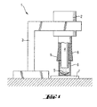
- the inspection device 1 illustrated schematically in fig. 1 consists of an ultrasonic processor 2, which is preferably fixed by a holder 3.
- the ultrasonic processor 2 has a rod-shaped sonotrode 4, which emits the ultrasonic waves.
- the ultrasonic processor 2 is preferably a UIP 250 appliance from Hielscher.
- the operating frequency of this device is 24 kHz ⁇ 1 kHz. It is, however, also conceivable to use other frequency ranges.
- the maximum ultrasonic intensity is 138 W/cm 2 and the maximum amplitude is in the region of ca. 250 ⁇ m.
- the butt end of the sonotrode 4 has a diameter of 14 mm. However, it is within the scope of the invention to use other devices with other parameters.
- the contact lens 5 is inserted into a holding container.
- This container is preferably a glass cuvette 6 of a basic cylindrical shape.
- the cuvette 6 is preferably filled with water or a comparable test liquid.
- the cuvette 6 is advantageously located on a spring-loaded holding plate 7. The positioning of the contact lens 5 in the cuvette 6 is of no importance to the examination process.
- the sonotrode 4 is plunged into the container 6, whereby the sonotrode 4 is immersed so deeply that the bottom is surrounded by water and thus the oscillations emanating from the sonotrode 4 are transferred to the water.
- the sonotrode 4 is suitably surrounded by a sealing sleeve 8, which is advantageously tuned to the vibration behaviour of the sonotrode 4.
- the sealing sleeve 8 is preferably made of Teflon and is pushed over the sonotrode 4 and held by a sealing ring at the oscillation node of the sonotrode 4.
- the sealing sleeve 8 preferably has a groove or recess 9 to cover the edge of the glass cuvette 6, so that no liquid can escape from the container 6.
- the sonotrode 4 is immersed into the container 6 to such an extent that the sealing sleeve 8 rests on the edge of the glass cuvette. In this way, a defined depth is given.
- the distance from the sonotrode 4 to the glass bottom of the cuvette 6, which is provided for the contact lens, is advantageously about 9 mm.
- the power and duration parameters of sonication are of crucial importance to the results of the examination. If too high power is applied, almost all the originally perfect lenses are destroyed by the ultrasonic treatment, and if the power is too low, defective lenses are also not destroyed. The same applies to the time during which the lens is exposed to sonication. By varying the time or the power, the energy applied overall is modified. The range regarded as acceptable for the examinations is 5 - 15% destruction of all lenses rated to be perfect. Since the lenses have been graded as perfect using an optical examination method, it is quite possible that the lenses have defects which can only be detected mechanically. For the ultrasonic processor used, a duration of 6 seconds and 70% of the maximum power of the device proved to be the optimum values. However, within the context of the invention, other settings for the duration and intensity of sonication may also be chosen. In particular, when choosing another ultrasonic processor, it may be expedient to modify the parameters.
- the examinations for defective lenses are suitably carried out using the above-mentioned setting.
- the examination results show that lenses especially with cracks were destroyed by almost 100%. For other types of defect, the destruction rate was not so high.
- the examination method is thus particularly suitable for detecting defective lenses with cracks.
Landscapes
- Physics & Mathematics (AREA)
- Health & Medical Sciences (AREA)
- Life Sciences & Earth Sciences (AREA)
- Chemical & Material Sciences (AREA)
- Analytical Chemistry (AREA)
- Biochemistry (AREA)
- General Health & Medical Sciences (AREA)
- General Physics & Mathematics (AREA)
- Immunology (AREA)
- Pathology (AREA)
- Eyeglasses (AREA)
- Investigating Or Analyzing Materials By The Use Of Ultrasonic Waves (AREA)
- Testing Of Optical Devices Or Fibers (AREA)
Abstract
Description
- The invention relates to a device and a method for the automatic inspection of ophthalmic lenses, especially contact lenses, in an automatic lens manufacturing process.
- The production of contact lenses using conventional methods, such as rotary processes for hard contact lenses and pouring processes for soft contact lenses in disposable plastic moulds is relatively expensive. As a rule, these contact lenses are used for a period of one year to one month. However, technical advancement in recent years has enabled contact lenses to be produced, which are worn only on one day and are replaced afterwards by new contact lenses. However, this has been made possible only through a high degree of automation of the production plants. Production of these contact lenses advantageously takes place using reusable mould halves, the matrix and the patrix, which normally consist of glass or quartz. Between these mould halves is a hollow cavity, which corresponds to the subsequent contact lens shape. Before closing the mould halves, a polymer solution is measured into the matrix. The upper mould half is exposed to UV light, which leads to crosslinking of the lens material. Subsequently, the lens is removed from the mould half with suction grips and is placed in the pack.
- In order to assure constant quality of the contact lenses, provisions are in place for automatic inspection of the contact lenses using industrial image-processing methods. In image-processing, the lenses are tested both in the mould halves and at the vacuum grips. An image processing method of this kind is described for example in EP patent 491 663. Moreover, using optical methods, not all defects of contact lenses can be detected without problems, so that defective contact lenses pass the quality control as defect-free and it is only the customer who establishes the defects when he removes the lens from the pack or even when he first wears the contact lens.
- The invention is based on the problem of providing an inspection device and an inspection method, which recognise the defective lenses, which are difficult to detect with conventional optical methods, with a high degree of reliability.
- The invention solves this problem with the features of
claim 1 and claim 10. As far as further embodiments of the device according to the invention and of the method are concerned, reference is made to the dependent claims. - According to the invention, the contact lenses are exposed to an ultrasonic field, which leads to destruction of defective lenses, while perfect lenses are as a rule not destroyed. In particular, the method is capable of detecting cracks in contact lenses which are often overlooked by optical methods, since this type of defect reacts especially sensitively to the soundwaves being received.
- Further details and advantages of the invention may be seen from the description that follows and the drawing. In the drawing,
- Fig. 1
- shows a schematic illustration of an inspection device according to the invention.
- The
inspection device 1 illustrated schematically in fig. 1 consists of anultrasonic processor 2, which is preferably fixed by aholder 3. Theultrasonic processor 2 has a rod-shaped sonotrode 4, which emits the ultrasonic waves. Theultrasonic processor 2 is preferably a UIP 250 appliance from Hielscher. The operating frequency of this device is 24 kHz ± 1 kHz. It is, however, also conceivable to use other frequency ranges. The maximum ultrasonic intensity is 138 W/cm2 and the maximum amplitude is in the region of ca. 250 µm. The butt end of the sonotrode 4 has a diameter of 14 mm. However, it is within the scope of the invention to use other devices with other parameters. - To examine a
contact lens 5 with theultrasonic processor 2, thecontact lens 5 is inserted into a holding container. This container is preferably aglass cuvette 6 of a basic cylindrical shape. Thecuvette 6 is preferably filled with water or a comparable test liquid. Thecuvette 6 is advantageously located on a spring-loaded holding plate 7. The positioning of thecontact lens 5 in thecuvette 6 is of no importance to the examination process. After inserting the contact lens in thecuvette 6, the sonotrode 4 is plunged into thecontainer 6, whereby the sonotrode 4 is immersed so deeply that the bottom is surrounded by water and thus the oscillations emanating from the sonotrode 4 are transferred to the water. The sonotrode 4 is suitably surrounded by a sealing sleeve 8, which is advantageously tuned to the vibration behaviour of the sonotrode 4. The sealing sleeve 8 is preferably made of Teflon and is pushed over the sonotrode 4 and held by a sealing ring at the oscillation node of the sonotrode 4. At the end facing thecuvette 6, the sealing sleeve 8 preferably has a groove or recess 9 to cover the edge of theglass cuvette 6, so that no liquid can escape from thecontainer 6. The sonotrode 4 is immersed into thecontainer 6 to such an extent that the sealing sleeve 8 rests on the edge of the glass cuvette. In this way, a defined depth is given. By expelling the water, it can be ensured that no air remains in thecontainer 6 and the ultrasound is ideally coupled in. The distance from the sonotrode 4 to the glass bottom of thecuvette 6, which is provided for the contact lens, is advantageously about 9 mm. After immersing the sonotrode 4 into thecuvette 6, theultrasonic processor 2 is switched on and thecontact lens 5 in thecuvette 6 is sonicated. - Using the device according to the invention, examinations were made of perfect and defective lenses, the quality of the lenses having already been examined using a shadowgraph.
- The power and duration parameters of sonication are of crucial importance to the results of the examination. If too high power is applied, almost all the originally perfect lenses are destroyed by the ultrasonic treatment, and if the power is too low, defective lenses are also not destroyed. The same applies to the time during which the lens is exposed to sonication. By varying the time or the power, the energy applied overall is modified. The range regarded as acceptable for the examinations is 5 - 15% destruction of all lenses rated to be perfect. Since the lenses have been graded as perfect using an optical examination method, it is quite possible that the lenses have defects which can only be detected mechanically. For the ultrasonic processor used, a duration of 6 seconds and 70% of the maximum power of the device proved to be the optimum values. However, within the context of the invention, other settings for the duration and intensity of sonication may also be chosen. In particular, when choosing another ultrasonic processor, it may be expedient to modify the parameters.
- The examinations for defective lenses are suitably carried out using the above-mentioned setting. The examination results show that lenses especially with cracks were destroyed by almost 100%. For other types of defect, the destruction rate was not so high. The examination method is thus particularly suitable for detecting defective lenses with cracks.
Claims (19)
- Inspection device for examining ophthalmic lenses, especially contact lenses, characterised by an ultrasonic processor (2) with a sonotrode (4) and a holding container (6) open at the top, into which one or more contact lenses (5) may be placed, which is filled with a test liquid, whereby the sonotrode (4) can be immersed into the holding container (6), and the contact lenses (5) located in the holding container (6) are sonicated with ultrasound.
- Inspection device according to claim 1, whereby the ultrasonic processes emits ultrasonic power.
- Inspection device according to claim 2, whereby the ultrasonic power intensity lies in the range of 80-150 W/cm2, especially 138 W/cm2.
- Inspection device according to claim 1, whereby the holding container (6) is of cylindrical shape.
- Inspection device according to claim 1 or 2, whereby the ultrasonic processor (2) operates in a frequency range of 20 to 30 kHz.
- Inspection device according to claim 5, whereby the frequency lies in the range of 24 kHz ± 1 kHz.
- Inspection device according to claim 1, whereby the butt end of the sonotrode (4) has a diameter of 14 mm.
- Inspection device according to claim 1, whereby the holding container (6) is mounted on a spring-loaded holding plate (7).
- Inspection device according to claim 1, whereby the sonotrode (4) is surrounded by a sealing sleeve (8), which seals off the holding container during immersion of the sonotrode (4).
- Method of inspecting ophthalmic lenses, especially contact lenses, for defects, whereby the lenses are surrounded by a test liquid and exposed to an ultrasonic field.
- Method according to claim 10, whereby the ultrasonic field is an ultrasonic power field.
- Method according to claim 11, whereby the power intensity of the ultrasonic field lies in the range of 80-150 W/cm2, especially 138 W/cm2.
- Method according to claim 10 or claim 12, whereby an ultrasonic processor (2) with a sonotrode (4) is used to produce the ultrasonic field.
- Method according to claim 10, whereby a cylindrical holding container (6) is used to position the contact lenses in the test liquid.
- Method according to claim 10, whereby the frequency range is from 20 to 30 kHz.
- Method according to claim 15, whereby the frequency range is from 24 kHz ± 1 kHz.
- Method according to claim 13, whereby a sonotrode (4) with a butt end of 14 mm diameter is used.
- Method according to claim 13, whereby the sonotrode (4) is surrounded by a sealing sleeve (8), which seals off the holding container (6) during immersion of the sonotrode (4).
- Method according to claim 10, whereby soft contact lenses are inspected.
Priority Applications (1)
| Application Number | Priority Date | Filing Date | Title |
|---|---|---|---|
| EP20010125064 EP1203952B1 (en) | 2000-10-23 | 2001-10-22 | Ultrasonic device for inspecting ophthalmic lenses |
Applications Claiming Priority (3)
| Application Number | Priority Date | Filing Date | Title |
|---|---|---|---|
| EP00122985 | 2000-10-23 | ||
| EP00122985 | 2000-10-23 | ||
| EP20010125064 EP1203952B1 (en) | 2000-10-23 | 2001-10-22 | Ultrasonic device for inspecting ophthalmic lenses |
Publications (2)
| Publication Number | Publication Date |
|---|---|
| EP1203952A1 true EP1203952A1 (en) | 2002-05-08 |
| EP1203952B1 EP1203952B1 (en) | 2012-02-08 |
Family
ID=26071538
Family Applications (1)
| Application Number | Title | Priority Date | Filing Date |
|---|---|---|---|
| EP20010125064 Expired - Lifetime EP1203952B1 (en) | 2000-10-23 | 2001-10-22 | Ultrasonic device for inspecting ophthalmic lenses |
Country Status (1)
| Country | Link |
|---|---|
| EP (1) | EP1203952B1 (en) |
Citations (3)
| Publication number | Priority date | Publication date | Assignee | Title |
|---|---|---|---|---|
| US4035082A (en) * | 1975-04-07 | 1977-07-12 | Kirk Optical Lens Co., Inc. | Method to test for chemically hardened glass lenses |
| EP0357905A2 (en) * | 1988-08-16 | 1990-03-14 | Toray Industries, Inc. | Method of measuring a profile of an object and an apparatus for carrying out the method |
| EP0491663A1 (en) * | 1990-12-19 | 1992-06-24 | Ciba-Geigy Ag | Procedure and apparatus for the examination of optical components, particularly ophthalmic components, and device for the illumination of transparent objects under examination |
-
2001
- 2001-10-22 EP EP20010125064 patent/EP1203952B1/en not_active Expired - Lifetime
Patent Citations (3)
| Publication number | Priority date | Publication date | Assignee | Title |
|---|---|---|---|---|
| US4035082A (en) * | 1975-04-07 | 1977-07-12 | Kirk Optical Lens Co., Inc. | Method to test for chemically hardened glass lenses |
| EP0357905A2 (en) * | 1988-08-16 | 1990-03-14 | Toray Industries, Inc. | Method of measuring a profile of an object and an apparatus for carrying out the method |
| EP0491663A1 (en) * | 1990-12-19 | 1992-06-24 | Ciba-Geigy Ag | Procedure and apparatus for the examination of optical components, particularly ophthalmic components, and device for the illumination of transparent objects under examination |
Non-Patent Citations (1)
| Title |
|---|
| DR. HIELSCHER GMBH: "UIP 250 Industrial Ultrasonic Processor 250W", DATA SHEET, 12 November 2000 (2000-11-12), XP002162188, Retrieved from the Internet <URL:http://www.hielscher.com/ultrasonics/uip250.htm> [retrieved on 20010306] * |
Also Published As
| Publication number | Publication date |
|---|---|
| EP1203952B1 (en) | 2012-02-08 |
Similar Documents
| Publication | Publication Date | Title |
|---|---|---|
| US7694568B2 (en) | Method for the nondestructive material testing of highly pure polycrystalline silicon | |
| US6776044B2 (en) | Ultrasonic device for inspection | |
| JPH04321186A (en) | Process and apparatus for inspecting optical part, especially optical part regarding eye, and apparatus for lighting transparent body to be inspected | |
| EP0404456A2 (en) | Disposable pin and cup with reuseable stem and collar for blood coagulation analyzer | |
| TW200837863A (en) | Apparatus and method for analyzing contaminants on wafer | |
| HU191463B (en) | Method and apparatus for observing the failure of fragile objects | |
| CN114813751B (en) | Method and device for detecting surface defects of silicon carbide ingot | |
| EP1203952B1 (en) | Ultrasonic device for inspecting ophthalmic lenses | |
| JPH04503005A (en) | Device for measuring optical density on the spot | |
| CN1128363C (en) | Method for transfusion of material to be tested for testing optical characteristics, and device and polarimeter thereof | |
| JPH0387654A (en) | Automatic ultrasonic flaw detection inspecting device for ball of water immersion type | |
| JPWO2006075615A1 (en) | Ultrasonic flaw detection method and ultrasonic flaw detection apparatus | |
| CN110596142A (en) | Terahertz imaging-based defect detection method and system | |
| US20140161542A1 (en) | Method and device for removing a contact lens from a container | |
| CN112881534B (en) | Ultrasonic detection test block, preparation method and application thereof | |
| JP4135329B2 (en) | Method for removing fibrin clot from specimen container and blood coagulation test method | |
| TW201815511A (en) | Method for cutting cell sheet | |
| CN221649439U (en) | Semiconductor finished product deformation detection device | |
| US20020125436A1 (en) | Detection of ophthalmic mouldings in a package | |
| RU2653473C2 (en) | Method of testing and determining mechanical characteristics fruit exocarp and device therefor | |
| JPS62170847A (en) | Standard ceramics sample for non-destructive inspection | |
| CN218995182U (en) | A detection fixture for a micro-nano grating cathode assembly | |
| JPH09257758A (en) | Water immersion type ultrasonic defect inspection method | |
| EP1927409A1 (en) | Method for handling contact lens | |
| EP1050470A1 (en) | Detection of ophthalmic mouldings in a package |
Legal Events
| Date | Code | Title | Description |
|---|---|---|---|
| PUAI | Public reference made under article 153(3) epc to a published international application that has entered the european phase |
Free format text: ORIGINAL CODE: 0009012 |
|
| 17P | Request for examination filed |
Effective date: 20011022 |
|
| AK | Designated contracting states |
Kind code of ref document: A1 Designated state(s): AT BE CH CY DE DK ES FI FR GB GR IE IT LI LU MC NL PT SE TR |
|
| AX | Request for extension of the european patent |
Free format text: AL;LT;LV;MK;RO;SI |
|
| AKX | Designation fees paid |
Designated state(s): AT BE CH CY DE DK ES FI FR GB GR IE IT LI LU MC NL PT SE TR |
|
| RAP1 | Party data changed (applicant data changed or rights of an application transferred) |
Owner name: NOVARTIS PHARMA GMBH Owner name: NOVARTIS AG |
|
| RAP1 | Party data changed (applicant data changed or rights of an application transferred) |
Owner name: NOVARTIS PHARMA GMBH Owner name: NOVARTIS AG |
|
| RAP1 | Party data changed (applicant data changed or rights of an application transferred) |
Owner name: NOVARTIS AG |
|
| 17Q | First examination report despatched |
Effective date: 20080313 |
|
| GRAP | Despatch of communication of intention to grant a patent |
Free format text: ORIGINAL CODE: EPIDOSNIGR1 |
|
| GRAS | Grant fee paid |
Free format text: ORIGINAL CODE: EPIDOSNIGR3 |
|
| GRAA | (expected) grant |
Free format text: ORIGINAL CODE: 0009210 |
|
| AK | Designated contracting states |
Kind code of ref document: B1 Designated state(s): AT BE CH CY DE DK ES FI FR GB GR IE IT LI LU MC NL PT SE TR |
|
| REG | Reference to a national code |
Ref country code: GB Ref legal event code: FG4D |
|
| REG | Reference to a national code |
Ref country code: AT Ref legal event code: REF Ref document number: 545018 Country of ref document: AT Kind code of ref document: T Effective date: 20120215 Ref country code: CH Ref legal event code: EP |
|
| REG | Reference to a national code |
Ref country code: DE Ref legal event code: R096 Ref document number: 60146087 Country of ref document: DE Effective date: 20120405 |
|
| REG | Reference to a national code |
Ref country code: NL Ref legal event code: VDEP Effective date: 20120208 |
|
| PG25 | Lapsed in a contracting state [announced via postgrant information from national office to epo] |
Ref country code: NL Free format text: LAPSE BECAUSE OF FAILURE TO SUBMIT A TRANSLATION OF THE DESCRIPTION OR TO PAY THE FEE WITHIN THE PRESCRIBED TIME-LIMIT Effective date: 20120208 |
|
| PG25 | Lapsed in a contracting state [announced via postgrant information from national office to epo] |
Ref country code: BE Free format text: LAPSE BECAUSE OF FAILURE TO SUBMIT A TRANSLATION OF THE DESCRIPTION OR TO PAY THE FEE WITHIN THE PRESCRIBED TIME-LIMIT Effective date: 20120208 Ref country code: GR Free format text: LAPSE BECAUSE OF FAILURE TO SUBMIT A TRANSLATION OF THE DESCRIPTION OR TO PAY THE FEE WITHIN THE PRESCRIBED TIME-LIMIT Effective date: 20120509 Ref country code: FI Free format text: LAPSE BECAUSE OF FAILURE TO SUBMIT A TRANSLATION OF THE DESCRIPTION OR TO PAY THE FEE WITHIN THE PRESCRIBED TIME-LIMIT Effective date: 20120208 Ref country code: PT Free format text: LAPSE BECAUSE OF FAILURE TO SUBMIT A TRANSLATION OF THE DESCRIPTION OR TO PAY THE FEE WITHIN THE PRESCRIBED TIME-LIMIT Effective date: 20120608 |
|
| REG | Reference to a national code |
Ref country code: AT Ref legal event code: MK05 Ref document number: 545018 Country of ref document: AT Kind code of ref document: T Effective date: 20120208 |
|
| PG25 | Lapsed in a contracting state [announced via postgrant information from national office to epo] |
Ref country code: CY Free format text: LAPSE BECAUSE OF FAILURE TO SUBMIT A TRANSLATION OF THE DESCRIPTION OR TO PAY THE FEE WITHIN THE PRESCRIBED TIME-LIMIT Effective date: 20120208 |
|
| PG25 | Lapsed in a contracting state [announced via postgrant information from national office to epo] |
Ref country code: DK Free format text: LAPSE BECAUSE OF FAILURE TO SUBMIT A TRANSLATION OF THE DESCRIPTION OR TO PAY THE FEE WITHIN THE PRESCRIBED TIME-LIMIT Effective date: 20120208 Ref country code: SE Free format text: LAPSE BECAUSE OF FAILURE TO SUBMIT A TRANSLATION OF THE DESCRIPTION OR TO PAY THE FEE WITHIN THE PRESCRIBED TIME-LIMIT Effective date: 20120208 |
|
| PG25 | Lapsed in a contracting state [announced via postgrant information from national office to epo] |
Ref country code: IT Free format text: LAPSE BECAUSE OF FAILURE TO SUBMIT A TRANSLATION OF THE DESCRIPTION OR TO PAY THE FEE WITHIN THE PRESCRIBED TIME-LIMIT Effective date: 20120208 |
|
| PLBE | No opposition filed within time limit |
Free format text: ORIGINAL CODE: 0009261 |
|
| STAA | Information on the status of an ep patent application or granted ep patent |
Free format text: STATUS: NO OPPOSITION FILED WITHIN TIME LIMIT |
|
| 26N | No opposition filed |
Effective date: 20121109 |
|
| PG25 | Lapsed in a contracting state [announced via postgrant information from national office to epo] |
Ref country code: AT Free format text: LAPSE BECAUSE OF FAILURE TO SUBMIT A TRANSLATION OF THE DESCRIPTION OR TO PAY THE FEE WITHIN THE PRESCRIBED TIME-LIMIT Effective date: 20120208 |
|
| REG | Reference to a national code |
Ref country code: DE Ref legal event code: R097 Ref document number: 60146087 Country of ref document: DE Effective date: 20121109 |
|
| PG25 | Lapsed in a contracting state [announced via postgrant information from national office to epo] |
Ref country code: MC Free format text: LAPSE BECAUSE OF NON-PAYMENT OF DUE FEES Effective date: 20121031 |
|
| REG | Reference to a national code |
Ref country code: CH Ref legal event code: PL |
|
| GBPC | Gb: european patent ceased through non-payment of renewal fee |
Effective date: 20121022 |
|
| REG | Reference to a national code |
Ref country code: IE Ref legal event code: MM4A |
|
| REG | Reference to a national code |
Ref country code: FR Ref legal event code: ST Effective date: 20130628 |
|
| PG25 | Lapsed in a contracting state [announced via postgrant information from national office to epo] |
Ref country code: GB Free format text: LAPSE BECAUSE OF NON-PAYMENT OF DUE FEES Effective date: 20121022 Ref country code: LI Free format text: LAPSE BECAUSE OF NON-PAYMENT OF DUE FEES Effective date: 20121031 Ref country code: IE Free format text: LAPSE BECAUSE OF NON-PAYMENT OF DUE FEES Effective date: 20121022 Ref country code: CH Free format text: LAPSE BECAUSE OF NON-PAYMENT OF DUE FEES Effective date: 20121031 Ref country code: DE Free format text: LAPSE BECAUSE OF NON-PAYMENT OF DUE FEES Effective date: 20130501 |
|
| REG | Reference to a national code |
Ref country code: DE Ref legal event code: R119 Ref document number: 60146087 Country of ref document: DE Effective date: 20130501 |
|
| PG25 | Lapsed in a contracting state [announced via postgrant information from national office to epo] |
Ref country code: FR Free format text: LAPSE BECAUSE OF NON-PAYMENT OF DUE FEES Effective date: 20121031 |
|
| PG25 | Lapsed in a contracting state [announced via postgrant information from national office to epo] |
Ref country code: ES Free format text: LAPSE BECAUSE OF FAILURE TO SUBMIT A TRANSLATION OF THE DESCRIPTION OR TO PAY THE FEE WITHIN THE PRESCRIBED TIME-LIMIT Effective date: 20120519 |
|
| PG25 | Lapsed in a contracting state [announced via postgrant information from national office to epo] |
Ref country code: TR Free format text: LAPSE BECAUSE OF FAILURE TO SUBMIT A TRANSLATION OF THE DESCRIPTION OR TO PAY THE FEE WITHIN THE PRESCRIBED TIME-LIMIT Effective date: 20120208 |
|
| PG25 | Lapsed in a contracting state [announced via postgrant information from national office to epo] |
Ref country code: LU Free format text: LAPSE BECAUSE OF NON-PAYMENT OF DUE FEES Effective date: 20121022 |