EP1203948A1 - Heat conductivity measurement method and instrument and method of producing a heat insulating material - Google Patents
Heat conductivity measurement method and instrument and method of producing a heat insulating material Download PDFInfo
- Publication number
- EP1203948A1 EP1203948A1 EP01402777A EP01402777A EP1203948A1 EP 1203948 A1 EP1203948 A1 EP 1203948A1 EP 01402777 A EP01402777 A EP 01402777A EP 01402777 A EP01402777 A EP 01402777A EP 1203948 A1 EP1203948 A1 EP 1203948A1
- Authority
- EP
- European Patent Office
- Prior art keywords
- heat
- resistant material
- measured
- heat conductivity
- heat resistant
- Prior art date
- Legal status (The legal status is an assumption and is not a legal conclusion. Google has not performed a legal analysis and makes no representation as to the accuracy of the status listed.)
- Withdrawn
Links
Images



Classifications
-
- G—PHYSICS
- G01—MEASURING; TESTING
- G01N—INVESTIGATING OR ANALYSING MATERIALS BY DETERMINING THEIR CHEMICAL OR PHYSICAL PROPERTIES
- G01N25/00—Investigating or analyzing materials by the use of thermal means
- G01N25/18—Investigating or analyzing materials by the use of thermal means by investigating thermal conductivity
Definitions
- the present invention relates to the measurement of the heat conductivity of a material and the production of a heat insulating material.
- heat conductivity has been measured by a plate comparison method specified in JIS A 1412. That is, a test sample and a reference plate are placed one upon the other, a temperature difference is given to them, the difference in surface temperature between them is measured, and the heat conductivity of the test sample is obtained from the ratio and the heat conductivity of the reference plate.
- the heat conductivity of the vacuum insulation material is measured by a so-called reverse vacuum method that it is inspected visually whether the vacuum insulation material swells when the vacuum insulation material is placed in vacuum in a container.
- a method of measuring the heat conductivity of an object to be measured comprising generating heat between the object to be measured and a heat resistant material, causing heat to flow through the interior of the object to be measured and the interior of the heat resistant material, and obtaining the heat conductivity of the object to be measured from a temperature difference between at least two locations on the heat resistant material.
- thermoelectric generation area is divided into a central area and an area surrounding the central area.
- a method of measuring the above heat conductivity wherein the externally exposed surface of the heat resistant material is covered with a cover member.
- an instrument for measuring the heat conductivity of an object to be measured comprising a heat resistant material having heat resistance, a temperature difference measuring unit capable of measuring a temperature difference between two locations on the heat resistant material, and a heat generating unit placed on the surface of the heat resistant material, wherein the heat resistant material is placed such that the heat generating unit comes in contact with the surface of the object to be measured, and the heat conductivity of the object to be measured is obtained from a temperature difference between two locations on the heat resistant material.
- the heat generating unit comprises a main heat generating section for generating heat in a central area, and an auxiliary heat generating section for generating heat in an area surrounding the main heat generating section.
- a method of producing a heat insulating material whose heat conductivity is measured comprising generating heat between the heat insulating material and a heat resistant material, causing heat to flow through the interior of the heat insulating material and the interior of the heat resistant material and obtaining the heat conductivity of the heat insulating material from a temperature difference between at least two locations on the heat resistant material.
- a seventh aspect of the present invention there is provided a method of producing a heat insulating material, wherein the heat generation area is divided into a central area and an area surrounding the central area.
- the heat conductivity measuring instrument 1 measures the heat conductivity of an object 6 to be measured, such as a heat insulating material, by contacting the object.
- the heat conductivity measuring instrument 1 comprises a heat resistant material 3 and a heat generating unit 2.
- the heat resistant material 3 is used to measure an internal temperature difference.
- the heat insulating material can include a vacuum insulation material.
- Heat is generated between the object 6 to be measured and the heat resistant material 3 by the heat generating unit 2 and flows through the object 6 to be measured and the heat resistant material 3.
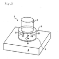
- the heat conductivity of the object 6 to be measured can be obtained from a temperature difference produced by a heat flow 31 ( Figure 2) flowing through the interior of the heat resistant material 3.
- a heat flow 31 Figure 2 flowing through the interior of the heat resistant material 3.
- the heat conductivity of the object 6 to be measured is high, the amount of heat flowing through the heat resistant material 3 becomes small, whereby the internal temperature difference of the heat resistant material 3 becomes small.
- the heat conductivity of the object 6 to be measured is low, the amount of heat flowing through the heat resistant material 3 becomes large, whereby the internal temperature difference of the heat resistant material 3 becomes large.
- the heat conductivity of the object 6 to be measured can be measured indirectly.
- any material is acceptable as the heat resistant material 3 if a temperature difference is produced between two points of the heat resistant material when a heat flow 31 is existent.
- super silica may be used as the heat resistant material 3.
- Super silica is an inorganic material which is hardly changed by temperature variations and has a heat conductivity of 0.0438 W/mK (when dried).
- a temperature difference measuring unit 5 for measuring a temperature difference between at least two locations within the interior of the heat resistant material 3 is placed in the interior of the heat resistant material 3.
- the temperature difference between two points is measured at three pairs of locations (A, a), (B, b) and (C, c) to increase accuracy.
- locations of the two points to be measured to obtain temperature differences are spaced apart in the direction of the heat flow 31, a temperature difference is easily measured.
- three locations (A, B, C) are on the surface in contact with the heat generating unit 2 and the other three locations (a, b, c) are spaced vertically from the three locations (A, B, C) as oriented in Figure 2.
- thermocouple may be used.
- the thermocouple is, for example, of a constantan type, made from copper-constantan, consists of three pairs connected in series, and has a line diameter of 0.1 mm and a resistance value of 15 .
- Cold contact points are located in the interior of the heat resistant material (for example, 20 mm away from the heat generating unit).
- Hot contact points are located at three locations (A, B, C) which are equally spaced apart on the top of the main heat generating section 21 ( Figure 3) of the heat generating unit 2.
- any heat generating unit is acceptable as the heat generating unit 2 if it can be interposed between the object 6 to be measured and the heat resistant material 3, and can transmit heat to the interior of the object 6 to be measured and the interior of the heat resistant material 3.
- the heat generating unit 2 has a double structure consisting of a main heat generation section 21 for generating a heat flow to be measured, and an auxiliary heat generating section 22, located around the main heat generating section, for preventing a heat bridge in a transverse direction. If the heat bridge in a transverse direction can be prevented, only the main heat generating section 21 will suffice.
- the heat generating unit 2 can be made of a thin film formed by joining together a cover layer and a constantan sheet and forming a heater pattern by etching.
- the main heater of the main heat generating section 21 has an outer diameter of 28 mm, an internal resistance of about 45 , and a supply current of 100 mA.
- the guard heater of the auxiliary heat generating section 22 is arranged in loop around the main heater and has a width of 6 mm, an internal resistance of about 45 , an d a supply current of 100 mA.
- the cover member 7 ( Figure 4) is used to cover the heat resistant material 3 in order to prevent the deterioration of the surface of the heat resistant material 3 and the influence of external ambient temperature.
- the cover member 7 is, for example, an acrylic cover having a heat conductivity of about 1.00 W/mK. A material which does not have too high conductivity unlike metal or too low conductivity unlike a heat insulating material is suitable.
- the cover member 7 is, for example, shaped like a cylindrical cover for covering the heat resistant material 3 from above as shown in Fig. 4.
- the outer diameter of this cylinder is 50 mm and the height thereof is 30 mm.
- the top portion of the cover member has a thickness of 5 mm and a hole having a diameter of 6 mm in the center.
- the side portion of the cover member has a thickness of 5 mm.
- any close contact aid material is acceptable as the close contact aid material 4 ( Figure 2) if it enables close contact among the heat resistant material 3, the heat generating unit 2 and the object 6 to be measured.
- the close contact aid material 4 is, for example, a brass weight placed on the heat resistant material 3 to enable close contact among the heat resistant material 3, the heat generating unit 2 and the object 6 to be measured by gravitation.
- Other biasing means can be substituted for the close contact aid material.
- the heat conductivity measuring system 8 measures the object 6 to be measured using the heat conductivity measuring instrument 1. For example, as shown in Fig. 5, it has a plurality of stages to measure the object 6 to be measured on each stage.
- the heat conductivity measuring instrument 1 and a display unit 83 which displays the state of measurement are placed on each stage.
- the heat conductivity measuring instrument 1 and the display unit 83 are electrically connected to a metering unit 82 and further to a personal computer 81 by RS-232C.
- the heat conductivity measuring system 8 can incorporate a bar code reader 84 as required to read a bar code attached to the object 6 to be measured to automatically identify a heat insulating material which is the object 6 to be measured.
- the display unit 83 displays the start of heat conductivity measurement and the state of the heat conductivity measuring instrument 1, for example, “measuring”, “cooling”, “out of operation”, “stand-by”, “measurable” and “the result of measurement”.
- the judgment of the measurement result is carried out by the personal computer 81 and then displayed on the display unit 83 such as a lamp.
- the metering unit 82 controls the display of the display unit 83 and the current of the heat generating unit 2 of the heat conductivity measuring instrument 1 and transfers the output of the temperature difference measuring unit 5 to the personal computer over RS-232C.
- a terminal base is used to connect the heat conductivity measuring instrument 1, to the metering unit 82.
- the metering unit 82 detects the disconnection of the heat conductivity measuring instrument 1 as well.
- the metering unit 82 has two constant current generating units for each stage to supply constant current, for example, 100 mA to the main heat generating section 21 and the auxiliary heat generating section 22.
- the personal computer 81 incorporates a program to display the result of measurement, input bar codes and store the result of measurement.
- the personal computer 81 performs the control of information from the metering unit 82, the heat conductivity measuring instruments and the bar code reader 84, and transfers data in the organization by LAN or other network as required.
- the stored measurement data include the production numbers of the objects to be measured, the stage numbers of the measuring heat conductivity measuring instruments, measurement values, measurement times and the results of judgment.
- the personal computer 81 and the metering unit 82 are powered on to input a stand-by voltage range ( ⁇ 0.05 mV), stand-by time (30 sec) and reference value (3.847 mV) into the personal computer 81.
- the display unit 83 displays "out of operation", "stand-by” or "cooling".
- the personal computer 81 reads a bar code given to the object 6 to be measured. At this point, the display unit 83 displays "measurable". The heat conductivity measuring instrument 1 is placed near the center of the surface of the object 6 to be measured and the "start" button is depressed. At this point, the display unit 83 displays "measuring”.
- the personal computer 81 counts the measuring time and terminates measurement after a predetermined duration, such as 120 seconds. At this point, the display unit 83 displays "cooling". When the output voltage of the thermocouple of the temperature difference measuring unit 5 is higher than the reference value, that is, 3.847 mV or more, the object 6 to be measured is accepted. The personal computer 81 and the display unit 83 display the result of judgment.
- the temperature difference measuring unit 5 is returned to the top of the brass stage and waits until the voltage returns to a stand-by voltage range. At this point, the display unit 83 displays "cooling". When the voltage falls within the stand-by voltage range, the stand-by time, for example, 30 seconds begins to be counted. At this point, the display unit 83 displays "out of operation”. When the voltage does not exceed the stand-by voltage range during the stand-by time, the next measurement is possible. When the voltage exceeds the stand-by voltage range, "cooling" is displayed and it waits until a voltage deviation is gone.
- thermocouple Since the heat conductivity of the object 6 to be measured and the temperature difference of the temperature difference measuring unit 5, that is, the output voltage of the thermocouple are proportional to each other, a proportional constant is measured for each heat conductivity measuring instrument 1 in advance. That is, the calibration of the heat conductivity measuring instrument 1 is carried out.
- a large number of objects to be measured are used for calibration as samples whose values are close to a reference value (W/mK) to be set. For example, when the heat conductivity is 6.00 x 10 -3 W/mK, five objects 6 to be measured whose heat conductivity's are already known are used for calibration. All the six objects 6 to be measured are measured by the heat conductivity measuring instruments 1 two or three times.
- the mean value of the outputs of the heat conductivity measuring instruments 1 which have measured five objects 6 to be measured is obtained.
- the result is shown in Table 1.
- the voltage (mV) is plotted on the axis of abscissa (x axis) and the heat conductivity (W/mK) is plotted on the axis of ordinate (y axis) and Fig. 6 shows a graph obtained by plotting the obtained values.
- the calibration curve is drawn by connecting the plotted mean values.
- the calibration curve is a straight line.
- y -0.0098x + 0.0432.
- the heat conductivity can be obtained from the equation, graph and table.
- the measurement value may be a voltage value when a thermocouple is specified or a temperature difference.
- the heat conductivity of the heat insulating material which is an object to be measured is measured by the above heat conductivity measuring instrument 1, the heat conductivity measuring system 8 or the heat conductivity measuring method.
- heat insulating materials having heat conductivity within a predetermined range can be obtained.
- a vacuum insulation material comprising a resin or fine powder having open-cells as a core material and coated with a metal film, resin film or a laminate film consisting of a metal and a resin
- acceptable products can be selected by carrying out a lot of accurate inspections in a short period of time.
- the present invention can present a number of advantages.
- the present invention makes it possible to obtain the heat conductivity of an object to be measured in a short period of time.
- the present invention makes it possible to measure the heat conductivity of even a vacuum insulation material.
- a heat bridge in a transverse direction easily occurs in a vacuum insulation material coated with a metal film or a laminate film consisting of a metal and a resin, when an auxiliary heat generating section is formed, the heat bridge can be easily prevented and the heat conductivity can be measured accurately in a short period of time.
- the present invention makes it possible to produce a heat insulating material having heat conductivity within a predetermined range easily.
Landscapes
- Physics & Mathematics (AREA)
- Health & Medical Sciences (AREA)
- Life Sciences & Earth Sciences (AREA)
- Chemical & Material Sciences (AREA)
- Analytical Chemistry (AREA)
- Biochemistry (AREA)
- General Health & Medical Sciences (AREA)
- General Physics & Mathematics (AREA)
- Immunology (AREA)
- Pathology (AREA)
- Investigating Or Analyzing Materials Using Thermal Means (AREA)
Abstract
A method of measuring the heat conductivity of an object to be measured,
comprising generating heat between the object to be measured and a heat resistant material,
causing heat to flow through the interior of the object to be measured and the interior of the heat
resistant material and obtaining the heat conductivity of the object to be measured from a
temperature difference between at least two points of the heat resistant material, a heat
conductivity measuring instrument using the same and a method of producing a heat insulating
material.
Description
- The present invention relates to the measurement of the heat conductivity of a material and the production of a heat insulating material.
- Heretofore, heat conductivity has been measured by a plate comparison method specified in JIS A 1412. That is, a test sample and a reference plate are placed one upon the other, a temperature difference is given to them, the difference in surface temperature between them is measured, and the heat conductivity of the test sample is obtained from the ratio and the heat conductivity of the reference plate. In the case of a vacuum insulation material, the heat conductivity of the vacuum insulation material is measured by a so-called reverse vacuum method that it is inspected visually whether the vacuum insulation material swells when the vacuum insulation material is placed in vacuum in a container.
- However, as the plate comparison method takes about 1 hour to measure heat conductivity, it is difficult to measure a large number of products. With the reverse vacuum method, accurate heat conductivity cannot be measured and when air is contained gradually, it is difficult to judge visually.
- It is an object of the present invention to measure heat conductivity in a short period of time.
- It is another object of the present invention to measure the heat conductivity of even a vacuum insulation material with ease.
- It is still another object of the present invention to produce a heat insulating material having heat conductivity within a predetermined range.
- According to a first aspect of the present invention, there is provided a method of measuring the heat conductivity of an object to be measured, comprising generating heat between the object to be measured and a heat resistant material, causing heat to flow through the interior of the object to be measured and the interior of the heat resistant material, and obtaining the heat conductivity of the object to be measured from a temperature difference between at least two locations on the heat resistant material.
- According to a second aspect of the present invention, there is provided a method of measuring the above heat conductivity, wherein the heat generation area is divided into a central area and an area surrounding the central area.
- According to a third aspect of the present invention, there is provided a method of measuring the above heat conductivity, wherein the externally exposed surface of the heat resistant material is covered with a cover member.
- According to a fourth aspect of the present invention, there is provided an instrument for measuring the heat conductivity of an object to be measured, comprising a heat resistant material having heat resistance, a temperature difference measuring unit capable of measuring a temperature difference between two locations on the heat resistant material, and a heat generating unit placed on the surface of the heat resistant material, wherein the heat resistant material is placed such that the heat generating unit comes in contact with the surface of the object to be measured, and the heat conductivity of the object to be measured is obtained from a temperature difference between two locations on the heat resistant material.
- According to a fifth aspect of the present invention, there is provided an instrument for measuring the above heat conductivity, wherein the heat generating unit comprises a main heat generating section for generating heat in a central area, and an auxiliary heat generating section for generating heat in an area surrounding the main heat generating section.
- According to a sixth aspect of the present invention, there is provided a method of producing a heat insulating material whose heat conductivity is measured, comprising generating heat between the heat insulating material and a heat resistant material, causing heat to flow through the interior of the heat insulating material and the interior of the heat resistant material and obtaining the heat conductivity of the heat insulating material from a temperature difference between at least two locations on the heat resistant material.
- According to a seventh aspect of the present invention, there is provided a method of producing a heat insulating material, wherein the heat generation area is divided into a central area and an area surrounding the central area.
- The above and other objects of the present invention will become readily apparent by reference to the following detailed description when considered in conjunction with the accompanying drawings wherein:
- Fig. 1 is a schematic diagram of a system for the measurement of heat conductivity according to an embodiment of the present invention;
- Fig. 2 is an isometric view of a heat conductivity measuring instrument according to an embodiment of the present invention;
- Fig. 3 is a plan view of a heat generating unit from the instrument of Figure 2;
- Fig. 4 is a perspective view of a cover member according to an embodiment of the present invention;
- Fig. 5 is a diagram for explaining a heat conductivity measuring system according to an embodiment of the present invention; and
- Fig. 6 is a diagram showing a calibration curve.
-
- Embodiments of the present invention will be described hereinbelow with reference to the accompanying drawings.
- The heat conductivity measuring instrument 1 measures the heat conductivity of an
object 6 to be measured, such as a heat insulating material, by contacting the object. For example, as shown in Fig. 1, the heat conductivity measuring instrument 1 comprises a heatresistant material 3 and aheat generating unit 2. The heatresistant material 3 is used to measure an internal temperature difference. The heat insulating material can include a vacuum insulation material. - Heat is generated between the
object 6 to be measured and the heatresistant material 3 by theheat generating unit 2 and flows through theobject 6 to be measured and the heatresistant material 3. The heat conductivity of theobject 6 to be measured can be obtained from a temperature difference produced by a heat flow 31 (Figure 2) flowing through the interior of the heatresistant material 3. For example, when the heat conductivity of theobject 6 to be measured is high, the amount of heat flowing through the heatresistant material 3 becomes small, whereby the internal temperature difference of the heatresistant material 3 becomes small. On the contrary, when the heat conductivity of theobject 6 to be measured is low, the amount of heat flowing through the heatresistant material 3 becomes large, whereby the internal temperature difference of the heatresistant material 3 becomes large. Using this principle, the heat conductivity of theobject 6 to be measured can be measured indirectly. - Any material is acceptable as the heat
resistant material 3 if a temperature difference is produced between two points of the heat resistant material when aheat flow 31 is existent. For example, super silica may be used as the heatresistant material 3. Super silica is an inorganic material which is hardly changed by temperature variations and has a heat conductivity of 0.0438 W/mK (when dried). - A temperature difference measuring unit 5 for measuring a temperature difference between at least two locations within the interior of the heat
resistant material 3 is placed in the interior of the heatresistant material 3. In Fig. 2, the temperature difference between two points is measured at three pairs of locations (A, a), (B, b) and (C, c) to increase accuracy. When the locations of the two points to be measured to obtain temperature differences are spaced apart in the direction of theheat flow 31, a temperature difference is easily measured. For example, three locations (A, B, C) are on the surface in contact with theheat generating unit 2 and the other three locations (a, b, c) are spaced vertically from the three locations (A, B, C) as oriented in Figure 2. - Any temperature difference measuring unit is acceptable as the temperature difference measuring unit 5 (Figure 1) if it can measure a temperature difference between two points. For example, a thermocouple may be used. The thermocouple is, for example, of a constantan type, made from copper-constantan, consists of three pairs connected in series, and has a line diameter of 0.1 mm and a resistance value of 15 . Cold contact points are located in the interior of the heat resistant material (for example, 20 mm away from the heat generating unit). Hot contact points are located at three locations (A, B, C) which are equally spaced apart on the top of the main heat generating section 21 (Figure 3) of the
heat generating unit 2. - Any heat generating unit is acceptable as the
heat generating unit 2 if it can be interposed between theobject 6 to be measured and the heatresistant material 3, and can transmit heat to the interior of theobject 6 to be measured and the interior of the heatresistant material 3. As shown in Fig. 3, theheat generating unit 2 has a double structure consisting of a mainheat generation section 21 for generating a heat flow to be measured, and an auxiliaryheat generating section 22, located around the main heat generating section, for preventing a heat bridge in a transverse direction. If the heat bridge in a transverse direction can be prevented, only the mainheat generating section 21 will suffice. - The heat generating
unit 2 can be made of a thin film formed by joining together a cover layer and a constantan sheet and forming a heater pattern by etching. In the illustrated embodiment, the main heater of the mainheat generating section 21 has an outer diameter of 28 mm, an internal resistance of about 45 , and a supply current of 100 mA. The guard heater of the auxiliaryheat generating section 22 is arranged in loop around the main heater and has a width of 6 mm, an internal resistance of about 45 , an d a supply current of 100 mA. - The cover member 7 (Figure 4) is used to cover the heat
resistant material 3 in order to prevent the deterioration of the surface of the heatresistant material 3 and the influence of external ambient temperature. The cover member 7 is, for example, an acrylic cover having a heat conductivity of about 1.00 W/mK. A material which does not have too high conductivity unlike metal or too low conductivity unlike a heat insulating material is suitable. The cover member 7 is, for example, shaped like a cylindrical cover for covering the heatresistant material 3 from above as shown in Fig. 4. The outer diameter of this cylinder is 50 mm and the height thereof is 30 mm. The top portion of the cover member has a thickness of 5 mm and a hole having a diameter of 6 mm in the center. The side portion of the cover member has a thickness of 5 mm. - Any close contact aid material is acceptable as the close contact aid material 4 (Figure 2) if it enables close contact among the heat
resistant material 3, theheat generating unit 2 and theobject 6 to be measured. The closecontact aid material 4 is, for example, a brass weight placed on the heatresistant material 3 to enable close contact among the heatresistant material 3, theheat generating unit 2 and theobject 6 to be measured by gravitation. Other biasing means can be substituted for the close contact aid material. - The heat conductivity measuring system 8 measures the
object 6 to be measured using the heat conductivity measuring instrument 1. For example, as shown in Fig. 5, it has a plurality of stages to measure theobject 6 to be measured on each stage. The heat conductivity measuring instrument 1 and adisplay unit 83 which displays the state of measurement are placed on each stage. The heat conductivity measuring instrument 1 and thedisplay unit 83 are electrically connected to ametering unit 82 and further to apersonal computer 81 by RS-232C. The heat conductivity measuring system 8 can incorporate abar code reader 84 as required to read a bar code attached to theobject 6 to be measured to automatically identify a heat insulating material which is theobject 6 to be measured. - The
display unit 83 displays the start of heat conductivity measurement and the state of the heat conductivity measuring instrument 1, for example, "measuring", "cooling", "out of operation", "stand-by", "measurable" and "the result of measurement". The judgment of the measurement result is carried out by thepersonal computer 81 and then displayed on thedisplay unit 83 such as a lamp. - The
metering unit 82 controls the display of thedisplay unit 83 and the current of theheat generating unit 2 of the heat conductivity measuring instrument 1 and transfers the output of the temperature difference measuring unit 5 to the personal computer over RS-232C. A terminal base is used to connect the heat conductivity measuring instrument 1, to themetering unit 82. Themetering unit 82 detects the disconnection of the heat conductivity measuring instrument 1 as well. Themetering unit 82 has two constant current generating units for each stage to supply constant current, for example, 100 mA to the mainheat generating section 21 and the auxiliaryheat generating section 22. - The
personal computer 81 incorporates a program to display the result of measurement, input bar codes and store the result of measurement. Thepersonal computer 81 performs the control of information from themetering unit 82, the heat conductivity measuring instruments and thebar code reader 84, and transfers data in the organization by LAN or other network as required. The stored measurement data include the production numbers of the objects to be measured, the stage numbers of the measuring heat conductivity measuring instruments, measurement values, measurement times and the results of judgment. - An embodiment of the method of measuring heat conductivity will be described hereinbelow.
- The
personal computer 81 and themetering unit 82 are powered on to input a stand-by voltage range (±0.05 mV), stand-by time (30 sec) and reference value (3.847 mV) into thepersonal computer 81. At this point, thedisplay unit 83 displays "out of operation", "stand-by" or "cooling". - The
personal computer 81 reads a bar code given to theobject 6 to be measured. At this point, thedisplay unit 83 displays "measurable". The heat conductivity measuring instrument 1 is placed near the center of the surface of theobject 6 to be measured and the "start" button is depressed. At this point, thedisplay unit 83 displays "measuring". - The
personal computer 81 counts the measuring time and terminates measurement after a predetermined duration, such as 120 seconds. At this point, thedisplay unit 83 displays "cooling". When the output voltage of the thermocouple of the temperature difference measuring unit 5 is higher than the reference value, that is, 3.847 mV or more, theobject 6 to be measured is accepted. Thepersonal computer 81 and thedisplay unit 83 display the result of judgment. - The temperature difference measuring unit 5 is returned to the top of the brass stage and waits until the voltage returns to a stand-by voltage range. At this point, the
display unit 83 displays "cooling". When the voltage falls within the stand-by voltage range, the stand-by time, for example, 30 seconds begins to be counted. At this point, thedisplay unit 83 displays "out of operation". When the voltage does not exceed the stand-by voltage range during the stand-by time, the next measurement is possible. When the voltage exceeds the stand-by voltage range, "cooling" is displayed and it waits until a voltage deviation is gone. - Since the heat conductivity of the
object 6 to be measured and the temperature difference of the temperature difference measuring unit 5, that is, the output voltage of the thermocouple are proportional to each other, a proportional constant is measured for each heat conductivity measuring instrument 1 in advance. That is, the calibration of the heat conductivity measuring instrument 1 is carried out. - A large number of objects to be measured are used for calibration as samples whose values are close to a reference value (W/mK) to be set. For example, when the heat conductivity is 6.00 x 10⁻³ W/mK, five
objects 6 to be measured whose heat conductivity's are already known are used for calibration. All the sixobjects 6 to be measured are measured by the heat conductivity measuring instruments 1 two or three times. - The mean value of the outputs of the heat conductivity measuring instruments 1 which have measured five
objects 6 to be measured is obtained. The result is shown in Table 1. The voltage (mV) is plotted on the axis of abscissa (x axis) and the heat conductivity (W/mK) is plotted on the axis of ordinate (y axis) and Fig. 6 shows a graph obtained by plotting the obtained values. The calibration curve is drawn by connecting the plotted mean values. The calibration curve is a straight line. When the calibration curve of Fig. 6 is expressed by an equation, y = -0.0098x + 0.0432.Objects to be measured (No.) Already known heat conductivity (W/mK) Voltage value
(mV)1 0.00352 4.025 2 0.00438 3.983 3 0.00503 3.932 4 0.00548 3.880 5 0.00622 3.762 - When the measurement value of the
object 6 to be measured is inserted into the previously obtained calibration curve, the heat conductivity can be obtained from the equation, graph and table. The measurement value may be a voltage value when a thermocouple is specified or a temperature difference. - The method of producing a heat insulating material will be described hereinbelow.
- When a heat insulating material is to be produced, the heat conductivity of the heat insulating material which is an object to be measured is measured by the above heat conductivity measuring instrument 1, the heat conductivity measuring system 8 or the heat conductivity measuring method.
- It is judged whether the heat conductivity of the measured heat insulating material falls within a predetermined range to select acceptable heat insulating materials. Thus, heat insulating materials having heat conductivity within a predetermined range can be obtained. Particularly in the case of a vacuum insulation material comprising a resin or fine powder having open-cells as a core material and coated with a metal film, resin film or a laminate film consisting of a metal and a resin, compared with the conventional plate comparison method or reverse vacuum method, acceptable products can be selected by carrying out a lot of accurate inspections in a short period of time.
- The present invention can present a number of advantages. For example, the present invention makes it possible to obtain the heat conductivity of an object to be measured in a short period of time. The present invention makes it possible to measure the heat conductivity of even a vacuum insulation material. Although a heat bridge in a transverse direction easily occurs in a vacuum insulation material coated with a metal film or a laminate film consisting of a metal and a resin, when an auxiliary heat generating section is formed, the heat bridge can be easily prevented and the heat conductivity can be measured accurately in a short period of time. The present invention makes it possible to produce a heat insulating material having heat conductivity within a predetermined range easily.
- It is readily apparent that the above-described embodiments have the advantage of wide commercial utility. It should be understood that the specific form of the invention hereinabove described is intended to be representative only, as certain modifications within the scope of these teachings will be apparent to those skilled in the art. Accordingly, reference should be made to the following claims in determining the full scope of the invention.
Claims (7)
- A method of measuring the heat conductivity of an object,comprising:generating heat between the object and a heat resistant material;causing heat to flow through the object and the heat resistant material; andcalculating the heat conductivity of the object from a temperature difference between at least two locations spaced apart about or inside the heat resistant material.
- The method of claim 1 characterized in that the heat generation area is divided into a central area and an area surrounding the central area.
- The method of claim 1 characterized in that the externally exposed surface of the heat resistant material is covered with a cover member.
- An instrument for measuring the heat conductivity of an object to be measured, comprising:a heat resistant material having heat resistance;a temperature difference measuring unit capable of measuring a temperature difference between two locations spaced apart about or within the heat resistant material; anda heat generating unit placed on the surface of the heat resistant material, whereinthe heat resistant material is placed such that the heat generating unit comes in contact with the surface of the object to be measured, and the heat conductivity of the object to be measured is obtained from a temperature difference between two points of the heat resistant material.
- The instrument of claim 4 characterized in that the heat generating unit comprises a main heat generating section for generating heat in a central area and an auxiliary heat generating section for generating heat in an area surrounding the main heat generating section.
- A method of determining the suitability of a heat insulating material, comprising an inspection step in which heat is generated between the heat insulating material and a heat resistant material and caused to flow through the heat insulating material and the heat resistant material, and a measurement step in which the heat conductivity of the heat insulating material is obtained from a temperature difference between at least two points of the heat resistant material.
- The method of claim 6 characterized in that the heat generation area is divided into a central area and an area surrounding the central area.
Applications Claiming Priority (2)
| Application Number | Priority Date | Filing Date | Title |
|---|---|---|---|
| JP2000327333 | 2000-10-26 | ||
| JP2000327333A JP2002131257A (en) | 2000-10-26 | 2000-10-26 | Thermal conductivity measuring method, measuring apparatus and method of manufacturing heat insulating material |
Publications (1)
| Publication Number | Publication Date |
|---|---|
| EP1203948A1 true EP1203948A1 (en) | 2002-05-08 |
Family
ID=18804370
Family Applications (1)
| Application Number | Title | Priority Date | Filing Date |
|---|---|---|---|
| EP01402777A Withdrawn EP1203948A1 (en) | 2000-10-26 | 2001-10-25 | Heat conductivity measurement method and instrument and method of producing a heat insulating material |
Country Status (5)
| Country | Link |
|---|---|
| US (1) | US6991366B2 (en) |
| EP (1) | EP1203948A1 (en) |
| JP (1) | JP2002131257A (en) |
| KR (1) | KR20020032316A (en) |
| CN (1) | CN1204395C (en) |
Cited By (1)
| Publication number | Priority date | Publication date | Assignee | Title |
|---|---|---|---|---|
| EP2840386A1 (en) * | 2004-12-16 | 2015-02-25 | Atlantic Business Centre of Excellence and Commercialization of Innovation Ltd. | Apparatus for monitoring materials |
Families Citing this family (35)
| Publication number | Priority date | Publication date | Assignee | Title |
|---|---|---|---|---|
| US6636062B2 (en) * | 2001-04-10 | 2003-10-21 | Delta Design, Inc. | Temperature control device for an electronic component |
| JP3858660B2 (en) * | 2001-10-10 | 2006-12-20 | 株式会社日立製作所 | Measuring method of thermal resistance of resin |
| JP4155749B2 (en) * | 2002-03-20 | 2008-09-24 | 日本碍子株式会社 | Method for measuring thermal conductivity of honeycomb structure |
| GB2399409B (en) * | 2003-01-20 | 2006-03-15 | Rolton Group Ltd | Identification of materials by non destructive testing |
| CN1328581C (en) * | 2003-12-05 | 2007-07-25 | 鸿富锦精密工业(深圳)有限公司 | Device for measuring heat coductivity coefficient |
| US7226206B2 (en) * | 2005-05-12 | 2007-06-05 | Guardian Building Products, Inc. | Dynamic heat flow meter for measuring thermal properties of insulation or the like, and corresponding method |
| US7748197B2 (en) * | 2005-05-12 | 2010-07-06 | Guardian Building Products, Inc. | Method and/or system for compensating for effects of heat flow and/or air flow through fiberglass insulation |
| US7802917B2 (en) * | 2005-08-05 | 2010-09-28 | Lam Research Corporation | Method and apparatus for chuck thermal calibration |
| US7490981B2 (en) * | 2005-12-01 | 2009-02-17 | Basf Catalysts Llc | Method for determining thermal effusivity and/or thermal conductivity of sheet material |
| US20070230536A1 (en) * | 2006-03-28 | 2007-10-04 | Mtu Aero Engines Gmbh | Method and apparatus for detection of flaws in a metal component |
| DE102006045471A1 (en) * | 2006-09-26 | 2008-04-03 | Va-Q-Tec Ag | Method for determining the gas pressure in evacuated bodies |
| JP4980147B2 (en) * | 2007-06-07 | 2012-07-18 | 株式会社ベテル | Thermophysical property measuring device, thermophysical property measuring method |
| US8005655B2 (en) * | 2008-02-26 | 2011-08-23 | Kimberly-Clark Worldwide, Inc. | Thermal comfort model having multiple fabric layers |
| US8577650B2 (en) * | 2008-02-26 | 2013-11-05 | Kimberly-Clark Worldwide, Inc. | User interface for modeling thermal comfort |
| JP2010143602A (en) * | 2008-12-17 | 2010-07-01 | Nichias Corp | Heat insulating container and method for examining it |
| SE534185C2 (en) * | 2009-02-11 | 2011-05-24 | Bae Systems Haegglunds Ab | Device for thermally adjusting the temperature distribution of a surface |
| JP5362465B2 (en) * | 2009-06-17 | 2013-12-11 | 株式会社アイフェイズ | Thermal conductivity measuring method and thermal conductivity measuring device |
| US8220989B1 (en) | 2009-09-30 | 2012-07-17 | The United States Of America As Represented By The Administrator Of National Aeronautics And Space Administration | Method and apparatus for measuring thermal conductivity of small, highly insulating specimens |
| US8313236B2 (en) * | 2009-11-06 | 2012-11-20 | Agilent Technologies, Inc. | Thermal conductivity detector |
| US8882344B2 (en) | 2012-02-01 | 2014-11-11 | Samsung Electronics Co., Ltd. | Thermal insulation performance measurement apparatus and measurement method using the same |
| CN104374797A (en) * | 2013-08-12 | 2015-02-25 | 苏州维艾普新材料股份有限公司 | Rapid heat conductivity coefficient measuring device and method |
| CN103728338A (en) * | 2013-08-12 | 2014-04-16 | 太仓派欧技术咨询服务有限公司 | Device and method for electromagnetically testing heat conduction coefficient |
| JP2015078903A (en) * | 2013-10-17 | 2015-04-23 | 株式会社デンソー | Parameter setting method and simulation apparatus |
| WO2015099444A1 (en) * | 2013-12-24 | 2015-07-02 | 가톨릭대학교 산학협력단 | Apparatus and method for measuring thermal conductivity of burns |
| KR101636472B1 (en) | 2013-12-24 | 2016-07-07 | 가톨릭대학교 산학협력단 | Heat conduction measuring device and method for burn degree |
| JP6485206B2 (en) * | 2014-06-03 | 2019-03-20 | 株式会社デンソー | Heat flow distribution measuring device |
| JP6451395B2 (en) * | 2015-02-23 | 2019-01-16 | Tdk株式会社 | Sensor element |
| KR101715174B1 (en) | 2015-07-13 | 2017-03-22 | (주)선한엠엔티 | Apparatus for measuring thermal conductivity using hot-wire |
| JP6634546B2 (en) * | 2015-07-17 | 2020-01-22 | 英弘精機株式会社 | Thermal conductivity measuring device, thermal conductivity measuring method, and vacuum degree evaluation device |
| KR101706251B1 (en) | 2015-11-09 | 2017-02-14 | 부산대학교 산학협력단 | Apparatus and method for measuring thermal conductivity |
| US11193901B2 (en) | 2016-11-29 | 2021-12-07 | Eko Instruments Co., Ltd. | Thermal conductivity measuring device, thermal conductivity measuring method and vacuum evaluation device |
| CN107741436A (en) * | 2017-09-04 | 2018-02-27 | 上海海事大学 | The method of measuring the thermal conductivity of VIP under different vacuum degrees in a water bath inverse vacuum |
| CN108287030B (en) * | 2017-12-28 | 2020-02-14 | 中国航天空气动力技术研究院 | Method for measuring surface heat flow of embedded thermocouple |
| US11137362B2 (en) | 2019-12-10 | 2021-10-05 | Covestro Llc | Method for assessing the long-term thermal resistance of closed-cell thermal insulating foams at multiple mean temperatures |
| CN115840132A (en) * | 2022-12-27 | 2023-03-24 | 中国电子科技集团公司第五十二研究所 | Chip power consumption test system based on heat conduction principle |
Citations (3)
| Publication number | Priority date | Publication date | Assignee | Title |
|---|---|---|---|---|
| US3971246A (en) * | 1972-12-21 | 1976-07-27 | Showa Denko Kabushiki Kaisha | Method and apparatus for measuring the coefficient of thermal conductivity of a sample |
| DE2724846A1 (en) * | 1977-06-02 | 1978-12-14 | Erwin Keller | Thermal conductivity and heat flow measurement system - uses outer guard ring container surrounding heat measurement container |
| JPS61198046A (en) * | 1985-07-27 | 1986-09-02 | Showa Denko Kk | Method and instrument for measuring thermal conductivity |
Family Cites Families (39)
| Publication number | Priority date | Publication date | Assignee | Title |
|---|---|---|---|---|
| US3075377A (en) * | 1956-10-17 | 1963-01-29 | Owens Corning Fiberglass Corp | Apparatus for determining thermal conductivity of materials |
| US3114255A (en) * | 1961-12-18 | 1963-12-17 | Charles D Niven | Thermal conductivity apparatus |
| US3263485A (en) * | 1964-01-30 | 1966-08-02 | Minnesota Mining & Mfg | Apparatus for determining thermal conductivity |
| US3657644A (en) * | 1968-11-12 | 1972-04-18 | Nasa | Thermodielectric radiometer utilizing polymer film |
| DE2044225B2 (en) * | 1970-09-07 | 1973-03-08 | PROCEDURE FOR DETERMINING AND QUICKLY DETECTING THE INTERNAL THERMAL RESISTANCE FOR SEMI-CONDUCTOR COMPONENTS OF THE SAME TYPE | |
| US3720103A (en) * | 1970-11-03 | 1973-03-13 | Cornell Aeronautical Labor Inc | Heat flux measuring system |
| US3733887A (en) * | 1972-01-31 | 1973-05-22 | Borg Warner | Method and apparatus for measuring the thermal conductivity and thermo-electric properties of solid materials |
| US4236403A (en) * | 1978-06-14 | 1980-12-02 | Thermonetics Corporation | Means and techniques useful in establishing R values in insulation |
| US4264423A (en) * | 1979-09-17 | 1981-04-28 | The United States Of America As Represented By The Secretary Of The Army | Fluidic thermistor/fugacity device |
| PL139300B1 (en) * | 1983-04-27 | 1987-01-31 | Pan Ct Badan Molekularnych I M | Method of determination of thermal conductivity and heat storage capacity of materials and apparatus therefor |
| US4553852A (en) * | 1983-12-07 | 1985-11-19 | W. R. Grace & Co. | Apparatus and method for heat flow measurement |
| US4896281A (en) * | 1985-05-31 | 1990-01-23 | The Dow Chemical Company | Method for heat loss survey |
| JPS62172248A (en) * | 1986-01-27 | 1987-07-29 | Natl House Ind Co Ltd | Apparatus for testing heat resistance of heat insulating material |
| JP2610250B2 (en) | 1986-03-13 | 1997-05-14 | 株式会社東芝 | Thermal insulation plate and its inspection method |
| US4696578A (en) * | 1986-06-19 | 1987-09-29 | International Business Machines Corporation | Single chip thermal tester |
| JPS6413445A (en) * | 1987-07-07 | 1989-01-18 | Fujitsu Ltd | Method for calculating thermal resistance of heat radiating route from surface packaging type element |
| US4929089A (en) * | 1988-01-18 | 1990-05-29 | Ishikawajima-Harima Heavy Industries Co. | Apparatus for measuring temperatures indicative of thermal conductivity |
| PL158642B1 (en) * | 1988-05-20 | 1992-09-30 | Polska Akad Nauk Centrum | Method for determining heat conduction coefficient and a device for measuring the heat conduction coefficient of materials |
| JPH03200055A (en) * | 1989-12-28 | 1991-09-02 | Oki Electric Ind Co Ltd | Measuring method for thermal conductivity |
| US5112136A (en) * | 1990-09-24 | 1992-05-12 | Kiyoshi Sakuma | Method of and apparatus for measuring thermal conductivity |
| JPH0794951B2 (en) | 1990-10-18 | 1995-10-11 | 明星工業株式会社 | Vacuum insulation |
| DE69129104T2 (en) * | 1990-12-14 | 1998-11-19 | Anritsu Corp | SENSOR FOR MEASURING THE CHARACTERISTIC VALUE OF AN ELEMENT TO BE MEASURED USING CHANGES IN THERMAL RESISTANCE |
| JPH0678958B2 (en) | 1992-05-25 | 1994-10-05 | 株式会社東芝 | Vacuum insulation panel pressure inspection method |
| FR2695475B1 (en) * | 1992-09-10 | 1994-10-21 | Univ Nantes | Conductivity meter for transient measurement of the conductivity of an injectable material or not. |
| US5393351A (en) * | 1993-01-13 | 1995-02-28 | The United States Of America As Represented By The Secretary Of Commerce | Multilayer film multijunction thermal converters |
| US5297868A (en) * | 1993-06-23 | 1994-03-29 | At&T Bell Laboratories | Measuring thermal conductivity and apparatus therefor |
| JPH07294359A (en) | 1994-04-21 | 1995-11-10 | Kubota Corp | Vacuum insulation measuring device |
| US5881208A (en) * | 1995-12-20 | 1999-03-09 | Sematech, Inc. | Heater and temperature sensor array for rapid thermal processing thermal core |
| US5965606A (en) * | 1995-12-29 | 1999-10-12 | Allergan Sales, Inc. | Methods of treatment with compounds having RAR.sub.α receptor specific or selective activity |
| WO1997033161A1 (en) * | 1996-03-08 | 1997-09-12 | Holometrix, Inc. | Heat flow meter instruments |
| US6039471A (en) * | 1996-05-22 | 2000-03-21 | Integrated Device Technology, Inc. | Device for simulating dissipation of thermal power by a board supporting an electronic component |
| EP0878707A4 (en) * | 1996-10-22 | 2000-06-28 | Riken Kk | HEATER TYPE SENSOR |
| US6278051B1 (en) * | 1997-10-09 | 2001-08-21 | Vatell Corporation | Differential thermopile heat flux transducer |
| US6331075B1 (en) * | 1998-05-01 | 2001-12-18 | Administrator, National Aeronautics And Space Administration | Device and method for measuring thermal conductivity of thin films |
| US6183128B1 (en) * | 1999-05-03 | 2001-02-06 | Westvaco Corporation | Apparatus and method for determining paperboard thermal conductivity |
| JP3858660B2 (en) * | 2001-10-10 | 2006-12-20 | 株式会社日立製作所 | Measuring method of thermal resistance of resin |
| AU2003219737A1 (en) * | 2002-02-12 | 2003-09-04 | Massachusetts Institute Of Technology | Method and apparatus for characterization of devices and circuits |
| JP4155749B2 (en) * | 2002-03-20 | 2008-09-24 | 日本碍子株式会社 | Method for measuring thermal conductivity of honeycomb structure |
| US6663278B1 (en) * | 2002-07-11 | 2003-12-16 | Industrial Technologies Research Institute | Method for determining the thermal performance of a heat sink |
-
2000
- 2000-10-26 JP JP2000327333A patent/JP2002131257A/en not_active Withdrawn
-
2001
- 2001-10-16 CN CNB011364165A patent/CN1204395C/en not_active Expired - Fee Related
- 2001-10-19 KR KR1020010064792A patent/KR20020032316A/en not_active Ceased
- 2001-10-23 US US10/004,538 patent/US6991366B2/en not_active Expired - Fee Related
- 2001-10-25 EP EP01402777A patent/EP1203948A1/en not_active Withdrawn
Patent Citations (3)
| Publication number | Priority date | Publication date | Assignee | Title |
|---|---|---|---|---|
| US3971246A (en) * | 1972-12-21 | 1976-07-27 | Showa Denko Kabushiki Kaisha | Method and apparatus for measuring the coefficient of thermal conductivity of a sample |
| DE2724846A1 (en) * | 1977-06-02 | 1978-12-14 | Erwin Keller | Thermal conductivity and heat flow measurement system - uses outer guard ring container surrounding heat measurement container |
| JPS61198046A (en) * | 1985-07-27 | 1986-09-02 | Showa Denko Kk | Method and instrument for measuring thermal conductivity |
Non-Patent Citations (1)
| Title |
|---|
| PATENT ABSTRACTS OF JAPAN vol. 011, no. 026 (P - 539) 24 January 1987 (1987-01-24) * |
Cited By (2)
| Publication number | Priority date | Publication date | Assignee | Title |
|---|---|---|---|---|
| EP2840386A1 (en) * | 2004-12-16 | 2015-02-25 | Atlantic Business Centre of Excellence and Commercialization of Innovation Ltd. | Apparatus for monitoring materials |
| US10753894B2 (en) | 2004-12-16 | 2020-08-25 | C-THERM Technologies | Method and apparatus for monitoring materials |
Also Published As
| Publication number | Publication date |
|---|---|
| US6991366B2 (en) | 2006-01-31 |
| CN1204395C (en) | 2005-06-01 |
| CN1351256A (en) | 2002-05-29 |
| JP2002131257A (en) | 2002-05-09 |
| US20020136261A1 (en) | 2002-09-26 |
| KR20020032316A (en) | 2002-05-03 |
Similar Documents
| Publication | Publication Date | Title |
|---|---|---|
| EP1203948A1 (en) | Heat conductivity measurement method and instrument and method of producing a heat insulating material | |
| CA1174483A (en) | Fast-response thermocouple probe and method for making it | |
| US20080175304A1 (en) | Thermocouple circuit and method and system for forming same | |
| US4117712A (en) | Emissimeter and method of measuring emissivity | |
| EP0052857B1 (en) | Hardness tester | |
| GB2326721A (en) | Wire width measurement | |
| Bentley | Handbook of Temperature Measurement.: Volume 1, Temperature and Humidity Measurement | |
| EP0617271B1 (en) | Method for simultaneous determination of thermal conductivity and kinematic viscosity | |
| CN101464423A (en) | Thermal conductivity coefficient measurement instrument for solid material | |
| US6970256B1 (en) | Apparatus and methods for measuring thickness and refractive index | |
| JP2610250B2 (en) | Thermal insulation plate and its inspection method | |
| EP0984273A2 (en) | Device for measuring thermophysical properties of solid materials and method therefor | |
| US2972882A (en) | Apparatus for measuring coating thicknesses | |
| JP3468300B2 (en) | Method and apparatus for measuring thermal and electrical properties of thin film thermoelectric materials | |
| US7246570B2 (en) | Indication film for temperature and temperature distribution measurement and related method | |
| US3414811A (en) | Method and apparatus for testing the resistance characteristics of selfheated electrical resistors | |
| Parody-Morreale et al. | A differential scanning calorimeter for ice nucleation distribution studies—Application to bacterial nucleators | |
| Garrido | Peltier’s and Thomson’s coefficients of thermoelectric phenomena in the observable formulation | |
| US7877217B2 (en) | Electric ultimate defects analyzer detecting all defects in PCB/MCM | |
| CN113739689B (en) | Sensors and Systems | |
| Fomichov et al. | Measurement, control and recording in welding | |
| Zarr et al. | Calibration of thin heat flux sensors for building applications using ASTM C 1130 | |
| Bojkovski et al. | Automated system for evaluation of climatic chambers | |
| Diller | Practical heat flux measurement | |
| Kolosova et al. | A Numerical Study on Heat Transfer Across a Contact Pair. |
Legal Events
| Date | Code | Title | Description |
|---|---|---|---|
| PUAI | Public reference made under article 153(3) epc to a published international application that has entered the european phase |
Free format text: ORIGINAL CODE: 0009012 |
|
| AK | Designated contracting states |
Kind code of ref document: A1 Designated state(s): AT BE CH CY DE DK ES FI FR GB GR IE IT LI LU MC NL PT SE TR |
|
| AX | Request for extension of the european patent |
Free format text: AL;LT;LV;MK;RO;SI |
|
| 17P | Request for examination filed |
Effective date: 20020729 |
|
| AKX | Designation fees paid |
Designated state(s): BE DE FR GB IT NL |
|
| STAA | Information on the status of an ep patent application or granted ep patent |
Free format text: STATUS: THE APPLICATION IS DEEMED TO BE WITHDRAWN |
|
| 18D | Application deemed to be withdrawn |
Effective date: 20060802 |