EP1203706A2 - Resin piston for master cylinder in brake system, master cylinder, die for molding resin piston for master cylinder, and manufacturing method of resin piston for master cylinder - Google Patents
Resin piston for master cylinder in brake system, master cylinder, die for molding resin piston for master cylinder, and manufacturing method of resin piston for master cylinder Download PDFInfo
- Publication number
- EP1203706A2 EP1203706A2 EP01126014A EP01126014A EP1203706A2 EP 1203706 A2 EP1203706 A2 EP 1203706A2 EP 01126014 A EP01126014 A EP 01126014A EP 01126014 A EP01126014 A EP 01126014A EP 1203706 A2 EP1203706 A2 EP 1203706A2
- Authority
- EP
- European Patent Office
- Prior art keywords
- hole
- master cylinder
- molding
- concavity
- core
- Prior art date
- Legal status (The legal status is an assumption and is not a legal conclusion. Google has not performed a legal analysis and makes no representation as to the accuracy of the status listed.)
- Withdrawn
Links
Images



Classifications
-
- B—PERFORMING OPERATIONS; TRANSPORTING
- B29—WORKING OF PLASTICS; WORKING OF SUBSTANCES IN A PLASTIC STATE IN GENERAL
- B29C—SHAPING OR JOINING OF PLASTICS; SHAPING OF MATERIAL IN A PLASTIC STATE, NOT OTHERWISE PROVIDED FOR; AFTER-TREATMENT OF THE SHAPED PRODUCTS, e.g. REPAIRING
- B29C45/00—Injection moulding, i.e. forcing the required volume of moulding material through a nozzle into a closed mould; Apparatus therefor
- B29C45/0025—Preventing defects on the moulded article, e.g. weld lines, shrinkage marks
-
- B—PERFORMING OPERATIONS; TRANSPORTING
- B29—WORKING OF PLASTICS; WORKING OF SUBSTANCES IN A PLASTIC STATE IN GENERAL
- B29C—SHAPING OR JOINING OF PLASTICS; SHAPING OF MATERIAL IN A PLASTIC STATE, NOT OTHERWISE PROVIDED FOR; AFTER-TREATMENT OF THE SHAPED PRODUCTS, e.g. REPAIRING
- B29C45/00—Injection moulding, i.e. forcing the required volume of moulding material through a nozzle into a closed mould; Apparatus therefor
- B29C45/17—Component parts, details or accessories; Auxiliary operations
- B29C45/26—Moulds
- B29C45/2628—Moulds with mould parts forming holes in or through the moulded article, e.g. for bearing cages
-
- B—PERFORMING OPERATIONS; TRANSPORTING
- B29—WORKING OF PLASTICS; WORKING OF SUBSTANCES IN A PLASTIC STATE IN GENERAL
- B29C—SHAPING OR JOINING OF PLASTICS; SHAPING OF MATERIAL IN A PLASTIC STATE, NOT OTHERWISE PROVIDED FOR; AFTER-TREATMENT OF THE SHAPED PRODUCTS, e.g. REPAIRING
- B29C45/00—Injection moulding, i.e. forcing the required volume of moulding material through a nozzle into a closed mould; Apparatus therefor
- B29C45/17—Component parts, details or accessories; Auxiliary operations
- B29C45/26—Moulds
- B29C45/33—Moulds having transversely, e.g. radially, movable mould parts
-
- B—PERFORMING OPERATIONS; TRANSPORTING
- B60—VEHICLES IN GENERAL
- B60T—VEHICLE BRAKE CONTROL SYSTEMS OR PARTS THEREOF; BRAKE CONTROL SYSTEMS OR PARTS THEREOF, IN GENERAL; ARRANGEMENT OF BRAKING ELEMENTS ON VEHICLES IN GENERAL; PORTABLE DEVICES FOR PREVENTING UNWANTED MOVEMENT OF VEHICLES; VEHICLE MODIFICATIONS TO FACILITATE COOLING OF BRAKES
- B60T11/00—Transmitting braking action from initiating means to ultimate brake actuator without power assistance or drive or where such assistance or drive is irrelevant
- B60T11/10—Transmitting braking action from initiating means to ultimate brake actuator without power assistance or drive or where such assistance or drive is irrelevant transmitting by fluid means, e.g. hydraulic
- B60T11/16—Master control, e.g. master cylinders
-
- B—PERFORMING OPERATIONS; TRANSPORTING
- B29—WORKING OF PLASTICS; WORKING OF SUBSTANCES IN A PLASTIC STATE IN GENERAL
- B29L—INDEXING SCHEME ASSOCIATED WITH SUBCLASS B29C, RELATING TO PARTICULAR ARTICLES
- B29L2031/00—Other particular articles
- B29L2031/748—Machines or parts thereof not otherwise provided for
- B29L2031/7494—Pistons
Definitions
- the present invention relates to a resin piston for being mounted in a master cylinder in a brake system used for a vehicle and the like for transforming brake treading force into a fluid pressure to operate a brake mechanism formed in each wheel, and further relates to the master cylinder, a die for molding the resin piston for the master cylinder, and a manufacturing method of the resin piston for the master cylinder.
- a resin piston for a master cylinder As the prior art concerning such a kind of a resin piston for a master cylinder, a resin piston for a master cylinder can be cited that is disclosed in Japanese Utility Model Publication No. Hei. 2-28134 and Japanese Laid-Open Patent Publication No. 2000-159088.
- a resin piston for a master cylinder is molded by injection molding, as shown in Fig. 7, an upper die 11 and a lower die 12, and a core for molding a concavity 13 and a core 14 are combined, and then a resin material is injected through a resin material injection hole 21 formed in the core 14. Then, after the resin material has been solidified, the core for molding a concavity 13 and the core 14 are pulled out, and the upper die 11 and the lower die 12 are removed.
- a resin piston for a master cylinder 1 is molded.
- a valve mechanism 41 is fixed in a concavity 31 of the resin piston for a master cylinder 1 in a state such that a stem 42 being a part of the valve mechanism 41 is inserted into a communicating hole 32.
- the valve mechanism 41 opens its valve in a state such that the stem 42 is touched to a stopper pin 43 disposed in the through-hole 33 of the resin piston for a master cylinder 1, and closes the valve in a state such that the stem 42 is separated from the stopper pin 43.
- burrs are formed at a communicating section 51 in a direction to cover the communicating hole 32 along a surface at which the upper die 11 and the lower die 12 are touched with the core for molding a concavity 13.
- the burrs are formed because the resin material flows into small gaps between the surfaces at which the upper die 11 and the lower die 12 are touched to the core for molding a concavity 13 in the process of the molding of the resin piston for a master cylinder 1.
- the generation of the burrs depends on the precision of the dies, but it is very difficult to eliminate the generation of the burrs completely.
- One object of the present invention is to provide a resin piston for a master cylinder capable of preventing a valve mechanism from becoming impossible to work because the stem of the valve mechanism is caught by burrs generated in the communicating hole of the resin piston for a master cylinder in the process of the injection molding thereof.
- a first aspect of the present invention is a resin piston for a master cylinder including a through-hole through which a stopper pin being a component of a valve mechanism of the master cylinder is inserted, a concavity in which the valve mechanism is fixed by being inserted therein, and a communicating hole communicating with the through-hole from the concavity, the resin piston for a master cylinder being molded by the injection of a resin material, wherein a position of a burr to be generated by a flow of the resin material into a gap between a combined molding die and a core in a process of molding of the resin piston for a master cylinder by injection molding is a position but an inner wall surface of the communicating hole.
- the burr to be generated in the communicating hole of the resin piston for a master cylinder is the position but the inner wall surface of the communicating hole, the bur does not interfere with the movement of a stem inserted into the communicating hole.
- the resin piston for a master cylinder of the first aspect operation and an effect can be obtained such that it is prevented that the stem of the valve mechanism is caught by a burr that can be generated in the communicating hole of a resin piston for a master cylinder in the process of the injection molding to disable the valve mechanism from working.
- a second aspect of the invention is a resin piston for a master cylinder including a through-hole through which a stopper pin being a component of a valve mechanism of the master cylinder is inserted, a concavity in which the valve mechanism is fixed by being inserted therein, and a communicating hole communicating with the through-hole from the concavity, the resin piston for a master cylinder being molded by injection of a resin material, wherein: the through-hole is molded with a core for through-hole molding; the concavity and the communicating hole are molded with a core for molding a concavity; a part where the through-hole communicates with the communicating hole is molded in a state such that an end of the core for molding a concavity is impacted in an impact hole formed on the core for through-hole molding.
- the communicating part is molded in the state such that the end of the core for molding a concavity is impacted in an impact hole formed on the core for through-hole molding, a burr formed at the part where the communicating hole communicates with the through-hole is formed by the flow of the resin material into a gap between the end of the core for molding a concavity and the impact part.
- the bur formed at the part where the communicating hole communicates with the through-hole is formed in the shape of a protrusion into the through-hole along the inner wall surface of the communicating hole, the shape of the burr does not interfere with the movement of a stem inserted in the communicating hole.
- the resin piston for a master cylinder of the second aspect operation and an effect can be obtained such that it is prevented that the stem of the valve mechanism is caught by a burr that can be generated in the communicating hole of a resin piston for a master cylinder in the process of the injection molding to disable the valve mechanism from working.
- a third aspect of the invention is the resin piston for a master cylinder as in the second aspect, wherein: the resin piston for a master cylinder is molded with a die formed by a combination of a first die and a second die, the first die including a first core, the second die including a second core; and the core for through-hole molding is constructed by a combination of the first core and the second core, whereby the impact hole is formed.
- the die for molding the resin piston for a master cylinder By the construction of the die for molding the resin piston for a master cylinder in such a way, it becomes possible to form the first die and the second die in a symmetrical shape. Thereby, according to the resin piston for a master cylinder of the third aspect, operation and an effect can be obtained such that the manufacture of the die is made easy in addition to the operation and the effect of the resin piston for a master cylinder of the second aspect.
- a fourth aspect of the invention is the resin piston for a master cylinder as in any one of the aspects 1-3, wherein a groove making the inner wall surface nearby a part, with which the communicating hole communicates, of the through-hole flat in a direction in which the stopper pin is inserted.
- the surface of the through-hole becomes a flat surface nearby the impact hole which is formed in the core for through-hole molding and in which the core for molding a concavity is impacted.
- the precision of the core for through-hole molding in the vicinity of the impact hole easily heightened more than the case where the surface is a curved surface, and a burr generated in the vicinity of the impact hole can be made smaller than that in the case where the surface is a curved surface.
- a fifth aspect of the invention is the resin piston for a master cylinder as in the fourth aspect, wherein the width of the groove is narrower than that of the through-hole and wider than the diameter of the stopper pin.
- the position of a reciprocation end of the resin piston for a master cylinder, the reciprocation width of which is regulated by the stopper pin inserted in the through-hole while the resin piston is reciprocating becomes easy to adjust.
- the resin piston for a master cylinder of the fifth aspect operation and an effect can be obtained such that the positioning of the reciprocation end of the resin piston for a master cylinder becomes easy in addition to the operation and the effects of the resin piston for a master cylinder as in the fourth aspects.
- a sixth aspect of the invention is the resin piston for a master cylinder as in any one of the first to fifth aspects, wherein the through-hole includes a projecting part for preventing the stopper pin from being touched to the inner wall surface nearby a part with which the communicating hole communicates.
- a seventh aspect of the invention is a resin piston for a master cylinder including a through-hole through which a stopper pin being a component of a valve mechanism of the master cylinder is inserted, a concavity in which the valve mechanism is fixed by being inserted therein, and a communicating hole communicating with the through-hole from the concavity, the resin piston for a master cylinder being molded by injection of a resin material, wherein: the through-hole is molded with a core for through-hole molding; the concavity and the communicating hole are molded with a core for molding a concavity; an inner wall surface of the through-hole nearby a part where the communicating hole communicates with the through-hole is in a shape of a flat surface.
- the same operation and the same effect can be obtained as those of the resin piston for a master cylinder of the fourth aspect. Then, burrs can be made small regardless of the directions in which the burrs protrude.
- An eighth aspect of the invention is a master cylinder equipped with the resin piston for a master cylinder as in any one of the first to the seventh aspects.
- the master cylinder of the eighth aspect such operation and an effect can be obtained as are brought about by the resin piston for a master cylinder as in any one of the first to the seventh aspects in the master cylinder.
- a ninth aspect of the invention is a die for molding a resin piston for a master cylinder, the die molding a resin piston for a master cylinder, the resin piston for a master cylinder including a through-hole through which a stopper pin being a component of a valve mechanism of the master cylinder is inserted, a concavity in which the valve mechanism is fixed by being inserted therein, and a communicating hole communicating with the through-hole from the concavity, the resin piston for a master cylinder being molded by the injection of a resin material, the die comprising a core for through-hole molding for molding the through-hole and a core for molding a concavity for molding the concavity and the communicating hole, wherein a part where the through-hole communicates with the communicating hole is constructed such that the part is molded in a state in which an end of the core for molding a concavity is impacted in an impact hole formed on the core for through-hole molding.
- the same operation and the same effect can be obtained as those of the aforesaid resin piston for a master cylinder of the second aspect.
- a tenth aspect of the invention is a manufacturing method of a resin piston for a master cylinder for manufacturing a resin piston for a master cylinder including a through-hole through which a stopper pin being a component of a valve mechanism of the master cylinder is inserted, a concavity in which the valve mechanism is fixed by being inserted therein, and a communicating hole communicating with the through-hole from the concavity, the resin piston for a master cylinder being molded by the injection of a resin material, the manufacturing method comprising the steps of: molding the through-hole with a core for through-hole molding; molding the concavity and the communicating hole with a core for molding a concavity; and molding a part where the through-hole communicates with the communicating hole in a state such that an end of the core for molding a concavity is impacted in an impact hole formed on the core for through-hole molding.
- the same operation and the same effect can be obtained as those of the aforesaid resin piston for a master cylinder of the second aspect.
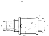
- Fig. 1 is a plan view of the resin piston for a master cylinder of a first embodiment according to the present invention
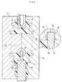
- Fig. 2 is a sectional view along the I-I line in a state such that a valve mechanism is inserted in the resin piston for a master cylinder of Fig. 1 to be touched with the resin piston.
- a resin piston for a master cylinder 1 is slidably impacted in the cylinder hole of a not shown master cylinder.
- the valve mechanism 41 is equipped in the concavity 31 in the shape of a circular concave.
- the valve mechanism 41 opens and shuts the communication of fluid between a fluid pressure chamber of the not shown master cylinder and an operation fluid reservoir.
- the communicating hole 32 is a circular hole having a diameter smaller than that of the concavity 31, and the communicating hole 32 makes the concavity 31 communicate with the through-hole 33.
- the through-hole 33 is an elongated hole formed in the central part in the axial direction of the resin piston for a master cylinder 1.
- the valve mechanism 41 includes the stem 42 inserted in the communicating hole 32, and the stopper pin 43 to which an end of the stem 42 can be touched and which is inserted in the through-hole 33.
- the valve mechanism 41 has a configuration to open the valve thereof by the touching of the end of the stem 42 to the stopper pin 43 owing to a push and a move of the resin piston for a master cylinder 1 caused by the operation of the master cylinder, and to close the valve by the separation of the end of the stem 42 from the stopper pin 43.
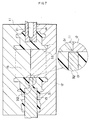
- Fig. 3 is a sectional view showing the resin piston for a master cylinder 1 of the first embodiment according to the preset invention and dies and cores for the injection molding of the resin piston for a master cylinder 1.
- a core for through-hole molding 15 is constructed by the junction of the cores, which are equipped to the upper die 11 and the lower die 12 severally to be integrated, on the extension line of the central axis of the core for molding a concavity 13.
- the through-hole 33 is molded with the core for through-hole molding 15.
- the concavity 31 to be equipped with the valve mechanism 41 and the communicating hole 32 making the concavity 31 communicate with the through-hole 33 are molded with the core for molding a concavity 13.
- the core for through-hole molding 15 includes an impact hole 16, in which a tip of the core for molding a concavity 13 is impacted.
- the upper die 11 and the lower die 12 severally have a symmetrical shape, and thereby the dies can easily be manufactured.
- a resin material is injected from the resin material injection hole 21 formed in the core 14 to mold the resin piston for a master cylinder 1.
- burrs which are generated by the flow of the resin material into a slight gap between the impact hole 16 and the core for molding a concavity 13 at the communicating section 51 where the communicating hole 32 communicates with the through-hole 33, are molded in a state of a protrusion into the through-hole 33 along the communicating hole 32 as shown in the drawing. Consequently, no burrs are generated on the inner wall surface of the communicating hole 32.
- the burrs molded at the communicating section 51 in such a way protrude into the through-hole 33 along the communicating hole 32, the burrs do not interfere with the operation of the stem 42 inserted in the communicating hole 32. Thereby, it can be prevented that the stem 42 is caught by the burrs molded at the communicating section 51 to disable the work of the valve mechanism 41.
- a resin piston for a master cylinder as shown in Fig. 4 can be cited.
- the position of the junction surface of the core for through-hole molding 15, which is placed on the extension line of the central axis of the core for molding a concavity 13 in the first embodiment is shifted from the extension line of the central axis of the core for molding a concavity 13.
- the implementation of the present invention is possible.
- the burrs molded at the communicating section 51 likewise in the first embodiment, protrude into the through-hole 33 along the communicating hole 32, the burrs do not interfere with the movement of the stem 42 that is inserted in the communicating hole 32. Then, it is possible to prevent the stem 42 from being caught by the burrs molded at the communicating section 51 to disable the operation of the valve mechanism 41.
- a resin piston for a master cylinder as shown in Fig. 5 is cited.
- a groove 34 is formed in addition to the form of the first embodiment or the second embodiments.
- the groove 34 is formed in such a way that the inner wall surface of the through-hole 33 becomes flat at a part thereof nearby a position where the communicating hole 32 communicates with the through-hole 33 in the direction of the insertion of the stopper pin 43.
- a surface of the through-hole 33 is made flat nearby the impact hole 16 which is formed in the core for through-hole molding 15 and in which the core for molding a concavity 13 is impacted. Then, the flat formation of the surface of the through-hole 33 nearby the impact hole 16 makes it easier to heighten the precision of the core for through-hole molding 15 nearby the impact hole 16 than in a case where the surface is a curved surface. Consequently, burrs to be generated nearby the impact hole 16 can be smaller in comparison with the case where the groove 34 is not formed and the surface of the through-hole 33 nearby the impact hole 16 is a curved surface.
- the contact area where burrs formed in a state such that they protrude into the through-hole 33 and the radiused surface of the stopper pin 43 becomes small when the radiused surface of the stopper pin 43 is touched to the part of the through-hole 33 where the communicating hole 32 communicates with the through-hole 33.
- the stopper pin 43 pushes and bends the burrs, and the burrs that have been pushed and bent catch the stem 42 inserted into the communicating hole 32.
- the surface of the through-hole 33 to which the stopper pin 43 inserted into the through-hole 33 is touched is a flat surface, the operation and the effect can also be obtained such that the positioning of the reciprocation end of the reciprocating resin piston for a master cylinder 1 can be performed more correctly when the position of the reciprocation end is set while the reciprocation width of the resin piston 1 is regulated by the stopper pin 43.
- a resin piston for a master cylinder is cited.
- the resin piston of the fourth embodiment is equipped with a projecting part 35 for preventing the stopper pin 43 from being touched to the inner wall surface of the through-hole 33 at a part thereof nearby a position where the communicating hole 32 communicates with the through-hole 33 in addition to the form of any one of the first to third embodiments.
- Fig. 6 is a sectional view of the resin piston for a master cylinder of the fourth embodiment according to the present invention.
Landscapes
- Engineering & Computer Science (AREA)
- Mechanical Engineering (AREA)
- Manufacturing & Machinery (AREA)
- Transportation (AREA)
- Transmission Of Braking Force In Braking Systems (AREA)
- Moulds For Moulding Plastics Or The Like (AREA)
Abstract
Description
- The present invention relates to a resin piston for being mounted in a master cylinder in a brake system used for a vehicle and the like for transforming brake treading force into a fluid pressure to operate a brake mechanism formed in each wheel, and further relates to the master cylinder, a die for molding the resin piston for the master cylinder, and a manufacturing method of the resin piston for the master cylinder.
- As the prior art concerning such a kind of a resin piston for a master cylinder, a resin piston for a master cylinder can be cited that is disclosed in Japanese Utility Model Publication No. Hei. 2-28134 and Japanese Laid-Open Patent Publication No. 2000-159088. When such a resin piston for a master cylinder is molded by injection molding, as shown in Fig. 7, an upper die 11 and a
lower die 12, and a core for molding aconcavity 13 and acore 14 are combined, and then a resin material is injected through a resinmaterial injection hole 21 formed in thecore 14. Then, after the resin material has been solidified, the core for molding aconcavity 13 and thecore 14 are pulled out, and the upper die 11 and thelower die 12 are removed. Thus, a resin piston for a master cylinder 1 is molded. - In the resin piston for a master cylinder 1 molded in such a way, as shown in Fig. 2, a
valve mechanism 41 is fixed in aconcavity 31 of the resin piston for a master cylinder 1 in a state such that a stem 42 being a part of thevalve mechanism 41 is inserted into a communicatinghole 32. Thevalve mechanism 41 opens its valve in a state such that the stem 42 is touched to astopper pin 43 disposed in the through-hole 33 of the resin piston for a master cylinder 1, and closes the valve in a state such that the stem 42 is separated from thestopper pin 43. - In the communicating
hole 32 of the resin piston for a master cylinder 1 that is molded by injection molding using thedies 11, 12 and thecores section 51 in a direction to cover the communicatinghole 32 along a surface at which the upper die 11 and thelower die 12 are touched with the core for molding aconcavity 13. The burrs are formed because the resin material flows into small gaps between the surfaces at which the upper die 11 and thelower die 12 are touched to the core for molding aconcavity 13 in the process of the molding of the resin piston for a master cylinder 1. The generation of the burrs depends on the precision of the dies, but it is very difficult to eliminate the generation of the burrs completely. Moreover, also in the case where glass fibers are mixed with the resin material with the object of the increase of the strength of the resin piston for a master cylinder 1, it is difficult to eliminate generated burrs because it is apprehended that, when the burrs are scraped off after injection molding, the resin surfaces at the places where the burrs have been scraped off become roughened and the stem 42 is caught by the roughened surfaces. Then, a problem is generated such that the stem 42 becomes unmovable because the stem 42 is caught by the burrs and then thevalve mechanism 41 becomes impossible to work. - One object of the present invention is to provide a resin piston for a master cylinder capable of preventing a valve mechanism from becoming impossible to work because the stem of the valve mechanism is caught by burrs generated in the communicating hole of the resin piston for a master cylinder in the process of the injection molding thereof.
- For attaining the object, a first aspect of the present invention is a resin piston for a master cylinder including a through-hole through which a stopper pin being a component of a valve mechanism of the master cylinder is inserted, a concavity in which the valve mechanism is fixed by being inserted therein, and a communicating hole communicating with the through-hole from the concavity, the resin piston for a master cylinder being molded by the injection of a resin material, wherein a position of a burr to be generated by a flow of the resin material into a gap between a combined molding die and a core in a process of molding of the resin piston for a master cylinder by injection molding is a position but an inner wall surface of the communicating hole.
- As described above, because the position of the burr to be generated in the communicating hole of the resin piston for a master cylinder is the position but the inner wall surface of the communicating hole, the bur does not interfere with the movement of a stem inserted into the communicating hole. According to the resin piston for a master cylinder of the first aspect, operation and an effect can be obtained such that it is prevented that the stem of the valve mechanism is caught by a burr that can be generated in the communicating hole of a resin piston for a master cylinder in the process of the injection molding to disable the valve mechanism from working.
- A second aspect of the invention is a resin piston for a master cylinder including a through-hole through which a stopper pin being a component of a valve mechanism of the master cylinder is inserted, a concavity in which the valve mechanism is fixed by being inserted therein, and a communicating hole communicating with the through-hole from the concavity, the resin piston for a master cylinder being molded by injection of a resin material, wherein: the through-hole is molded with a core for through-hole molding; the concavity and the communicating hole are molded with a core for molding a concavity; a part where the through-hole communicates with the communicating hole is molded in a state such that an end of the core for molding a concavity is impacted in an impact hole formed on the core for through-hole molding.
- As described above, because the communicating part is molded in the state such that the end of the core for molding a concavity is impacted in an impact hole formed on the core for through-hole molding, a burr formed at the part where the communicating hole communicates with the through-hole is formed by the flow of the resin material into a gap between the end of the core for molding a concavity and the impact part. As a result, because the bur formed at the part where the communicating hole communicates with the through-hole is formed in the shape of a protrusion into the through-hole along the inner wall surface of the communicating hole, the shape of the burr does not interfere with the movement of a stem inserted in the communicating hole. According to the resin piston for a master cylinder of the second aspect, operation and an effect can be obtained such that it is prevented that the stem of the valve mechanism is caught by a burr that can be generated in the communicating hole of a resin piston for a master cylinder in the process of the injection molding to disable the valve mechanism from working.
- A third aspect of the invention is the resin piston for a master cylinder as in the second aspect, wherein: the resin piston for a master cylinder is molded with a die formed by a combination of a first die and a second die, the first die including a first core, the second die including a second core; and the core for through-hole molding is constructed by a combination of the first core and the second core, whereby the impact hole is formed.
- By the construction of the die for molding the resin piston for a master cylinder in such a way, it becomes possible to form the first die and the second die in a symmetrical shape. Thereby, according to the resin piston for a master cylinder of the third aspect, operation and an effect can be obtained such that the manufacture of the die is made easy in addition to the operation and the effect of the resin piston for a master cylinder of the second aspect.
- A fourth aspect of the invention is the resin piston for a master cylinder as in any one of the aspects 1-3, wherein a groove making the inner wall surface nearby a part, with which the communicating hole communicates, of the through-hole flat in a direction in which the stopper pin is inserted.
- By the formation of such a groove in the through-hole, the surface of the through-hole becomes a flat surface nearby the impact hole which is formed in the core for through-hole molding and in which the core for molding a concavity is impacted. By the formation of the flat surface nearby the impact hole in such a way, the precision of the core for through-hole molding in the vicinity of the impact hole easily heightened more than the case where the surface is a curved surface, and a burr generated in the vicinity of the impact hole can be made smaller than that in the case where the surface is a curved surface. Thereby, according to the resin piston for a master cylinder of the fourth aspect, operation and an effect can be obtained such that burrs can be made small in addition to the operation and the effects of the resin piston for a master cylinder as in any one of the first to the third aspects.
- A fifth aspect of the invention is the resin piston for a master cylinder as in the fourth aspect, wherein the width of the groove is narrower than that of the through-hole and wider than the diameter of the stopper pin.
- By the formation of the width of the groove to be narrower than that of the through-hole and wider than the diameter of the stopper pin, the position of a reciprocation end of the resin piston for a master cylinder, the reciprocation width of which is regulated by the stopper pin inserted in the through-hole while the resin piston is reciprocating, becomes easy to adjust. Thereby, according to the resin piston for a master cylinder of the fifth aspect, operation and an effect can be obtained such that the positioning of the reciprocation end of the resin piston for a master cylinder becomes easy in addition to the operation and the effects of the resin piston for a master cylinder as in the fourth aspects.
- A sixth aspect of the invention is the resin piston for a master cylinder as in any one of the first to fifth aspects, wherein the through-hole includes a projecting part for preventing the stopper pin from being touched to the inner wall surface nearby a part with which the communicating hole communicates.
- By the construction such that the stopper pin inserted in the through-hole is not touched to the inner wall surface nearby a part with which the communicating hole communicates, there are no possibilities that the stopper pin pushes the burrs generated at that part to bend them. Thereby, according to the resin piston for a master cylinder of the sixth aspect, operation and an effect can be obtained such that it can be prevented that the burrs that have been pushed and bent interfere with the stem of the valve mechanism inserted in the communicating hole to disable the valve mechanism from working in addition to the operation and the effects of the resin piston for a master cylinder as in any one of the first to the fifth aspects.
- A seventh aspect of the invention is a resin piston for a master cylinder including a through-hole through which a stopper pin being a component of a valve mechanism of the master cylinder is inserted, a concavity in which the valve mechanism is fixed by being inserted therein, and a communicating hole communicating with the through-hole from the concavity, the resin piston for a master cylinder being molded by injection of a resin material, wherein: the through-hole is molded with a core for through-hole molding; the concavity and the communicating hole are molded with a core for molding a concavity; an inner wall surface of the through-hole nearby a part where the communicating hole communicates with the through-hole is in a shape of a flat surface.
- According to the resin piston for a master cylinder of the seventh aspect, the same operation and the same effect can be obtained as those of the resin piston for a master cylinder of the fourth aspect. Then, burrs can be made small regardless of the directions in which the burrs protrude.
- An eighth aspect of the invention is a master cylinder equipped with the resin piston for a master cylinder as in any one of the first to the seventh aspects.
- According to the master cylinder of the eighth aspect, such operation and an effect can be obtained as are brought about by the resin piston for a master cylinder as in any one of the first to the seventh aspects in the master cylinder.
- A ninth aspect of the invention is a die for molding a resin piston for a master cylinder, the die molding a resin piston for a master cylinder, the resin piston for a master cylinder including a through-hole through which a stopper pin being a component of a valve mechanism of the master cylinder is inserted, a concavity in which the valve mechanism is fixed by being inserted therein, and a communicating hole communicating with the through-hole from the concavity, the resin piston for a master cylinder being molded by the injection of a resin material, the die comprising a core for through-hole molding for molding the through-hole and a core for molding a concavity for molding the concavity and the communicating hole, wherein a part where the through-hole communicates with the communicating hole is constructed such that the part is molded in a state in which an end of the core for molding a concavity is impacted in an impact hole formed on the core for through-hole molding.
- According to the resin piston for a master cylinder molded by the injection molding with the die for molding a resin piston for a master cylinder of the ninth aspect, the same operation and the same effect can be obtained as those of the aforesaid resin piston for a master cylinder of the second aspect.
- A tenth aspect of the invention is a manufacturing method of a resin piston for a master cylinder for manufacturing a resin piston for a master cylinder including a through-hole through which a stopper pin being a component of a valve mechanism of the master cylinder is inserted, a concavity in which the valve mechanism is fixed by being inserted therein, and a communicating hole communicating with the through-hole from the concavity, the resin piston for a master cylinder being molded by the injection of a resin material, the manufacturing method comprising the steps of: molding the through-hole with a core for through-hole molding; molding the concavity and the communicating hole with a core for molding a concavity; and molding a part where the through-hole communicates with the communicating hole in a state such that an end of the core for molding a concavity is impacted in an impact hole formed on the core for through-hole molding.
- According to the resin piston for a master cylinder manufactured by the manufacturing method of a resin piston for a master cylinder of the tenth aspect, the same operation and the same effect can be obtained as those of the aforesaid resin piston for a master cylinder of the second aspect.
- The above and other objects, features and advantages of the present invention will become more apparent from the following description of the presently preferred exemplary embodiments of the invention taken in conjunction with the accompanying drawings, in which:
- Fig. 1 is a plan view of the resin piston for a master cylinder of a first embodiment according to the present invention;
- Fig. 2 is a sectional view along the I-I line in a state such that a valve mechanism is inserted in the resin piston for a master cylinder of Fig. 1 to be touched with the resin piston;
- Fig. 3 is a sectional view showing the resin piston for a master cylinder of the first embodiment according to the preset invention and dies and cores for the injection molding of the resin piston for a master cylinder;
- Fig. 4 is a sectional view showing the resin piston for a master cylinder of a second embodiment according to the preset invention and dies and cores for the injection molding of the resin piston for a master cylinder;
- Fig. 5 is a plan view of the resin piston for a master cylinder of a third embodiment according to the preset invention;
- Fig. 6 is a sectional view of the resin piston for a master cylinder of a fourth embodiment according to the preset invention; and
- Fig. 7 is a sectional view showing a prior art resin piston for a master cylinder and dies and cores for the injection molding of the resin piston for a master cylinder.
-
- Hereinafter, embodiments of the present invention are described by reference to the attached drawings.
- Fig. 1 is a plan view of the resin piston for a master cylinder of a first embodiment according to the present invention; and Fig. 2 is a sectional view along the I-I line in a state such that a valve mechanism is inserted in the resin piston for a master cylinder of Fig. 1 to be touched with the resin piston.
- A resin piston for a master cylinder 1 is slidably impacted in the cylinder hole of a not shown master cylinder. The
valve mechanism 41 is equipped in theconcavity 31 in the shape of a circular concave. Thevalve mechanism 41 opens and shuts the communication of fluid between a fluid pressure chamber of the not shown master cylinder and an operation fluid reservoir. The communicatinghole 32 is a circular hole having a diameter smaller than that of theconcavity 31, and the communicatinghole 32 makes theconcavity 31 communicate with the through-hole 33. The through-hole 33 is an elongated hole formed in the central part in the axial direction of the resin piston for a master cylinder 1. Thevalve mechanism 41 includes the stem 42 inserted in the communicatinghole 32, and thestopper pin 43 to which an end of the stem 42 can be touched and which is inserted in the through-hole 33. Thevalve mechanism 41, as being known, has a configuration to open the valve thereof by the touching of the end of the stem 42 to thestopper pin 43 owing to a push and a move of the resin piston for a master cylinder 1 caused by the operation of the master cylinder, and to close the valve by the separation of the end of the stem 42 from thestopper pin 43. - Fig. 3 is a sectional view showing the resin piston for a master cylinder 1 of the first embodiment according to the preset invention and dies and cores for the injection molding of the resin piston for a master cylinder 1.
- The upper die 11 and the
lower die 12 are combined, and the core for molding aconcavity 13 and the core 14 are combined with the combined upper die 11 and thelower die 12 at respective prescribed positions. A core for through-hole molding 15 is constructed by the junction of the cores, which are equipped to the upper die 11 and thelower die 12 severally to be integrated, on the extension line of the central axis of the core for molding aconcavity 13. The through-hole 33 is molded with the core for through-hole molding 15. Theconcavity 31 to be equipped with thevalve mechanism 41 and the communicatinghole 32 making theconcavity 31 communicate with the through-hole 33 are molded with the core for molding aconcavity 13. The core for through-hole molding 15 includes animpact hole 16, in which a tip of the core for molding aconcavity 13 is impacted. The upper die 11 and thelower die 12 severally have a symmetrical shape, and thereby the dies can easily be manufactured. - Then, a resin material is injected from the resin
material injection hole 21 formed in the core 14 to mold the resin piston for a master cylinder 1. At this time, burrs, which are generated by the flow of the resin material into a slight gap between theimpact hole 16 and the core for molding aconcavity 13 at the communicatingsection 51 where the communicatinghole 32 communicates with the through-hole 33, are molded in a state of a protrusion into the through-hole 33 along the communicatinghole 32 as shown in the drawing. Consequently, no burrs are generated on the inner wall surface of the communicatinghole 32. - Because the burrs molded at the communicating
section 51 in such a way protrude into the through-hole 33 along the communicatinghole 32, the burrs do not interfere with the operation of the stem 42 inserted in the communicatinghole 32. Thereby, it can be prevented that the stem 42 is caught by the burrs molded at the communicatingsection 51 to disable the work of thevalve mechanism 41. - Next, as a second embodiment according to the present invention, a resin piston for a master cylinder as shown in Fig. 4 can be cited. In the resin piston of the second embodiment, the position of the junction surface of the core for through-
hole molding 15, which is placed on the extension line of the central axis of the core for molding aconcavity 13 in the first embodiment, is shifted from the extension line of the central axis of the core for molding aconcavity 13. - Even if the core for through-
hole molding 15 is thus constructed, the implementation of the present invention is possible. In this case also, because the burrs molded at the communicatingsection 51, likewise in the first embodiment, protrude into the through-hole 33 along the communicatinghole 32, the burrs do not interfere with the movement of the stem 42 that is inserted in the communicatinghole 32. Then, it is possible to prevent the stem 42 from being caught by the burrs molded at the communicatingsection 51 to disable the operation of thevalve mechanism 41. - Furthermore, as a third embodiment according to the present invention, a resin piston for a master cylinder as shown in Fig. 5 is cited. In the resin piston of the third embodiment, a
groove 34 is formed in addition to the form of the first embodiment or the second embodiments. Thegroove 34 is formed in such a way that the inner wall surface of the through-hole 33 becomes flat at a part thereof nearby a position where the communicatinghole 32 communicates with the through-hole 33 in the direction of the insertion of thestopper pin 43. - By the provision of such a
groove 34 for the through-hole 33, a surface of the through-hole 33 is made flat nearby theimpact hole 16 which is formed in the core for through-hole molding 15 and in which the core for molding aconcavity 13 is impacted. Then, the flat formation of the surface of the through-hole 33 nearby theimpact hole 16 makes it easier to heighten the precision of the core for through-hole molding 15 nearby theimpact hole 16 than in a case where the surface is a curved surface. Consequently, burrs to be generated nearby theimpact hole 16 can be smaller in comparison with the case where thegroove 34 is not formed and the surface of the through-hole 33 nearby theimpact hole 16 is a curved surface. Moreover, because the inner wall surface of the through-hole 33 becomes flat nearby a position where the communicatinghole 32 communicates, the contact area where burrs formed in a state such that they protrude into the through-hole 33 and the radiused surface of thestopper pin 43 becomes small when the radiused surface of thestopper pin 43 is touched to the part of the through-hole 33 where the communicatinghole 32 communicates with the through-hole 33. - Consequently, it can be prevented that the stem 42 is caught by the burrs molded at the communicating
section 51 to disable the work of thevalve mechanism 41. Moreover, the following possibility becomes small. That is, thestopper pin 43 pushes and bends the burrs, and the burrs that have been pushed and bent catch the stem 42 inserted into the communicatinghole 32. Moreover, because the surface of the through-hole 33 to which thestopper pin 43 inserted into the through-hole 33 is touched is a flat surface, the operation and the effect can also be obtained such that the positioning of the reciprocation end of the reciprocating resin piston for a master cylinder 1 can be performed more correctly when the position of the reciprocation end is set while the reciprocation width of the resin piston 1 is regulated by thestopper pin 43. - Furthermore, as a fourth embodiment according to the present invention, a resin piston for a master cylinder is cited. The resin piston of the fourth embodiment is equipped with a projecting
part 35 for preventing thestopper pin 43 from being touched to the inner wall surface of the through-hole 33 at a part thereof nearby a position where the communicatinghole 32 communicates with the through-hole 33 in addition to the form of any one of the first to third embodiments. - Fig. 6 is a sectional view of the resin piston for a master cylinder of the fourth embodiment according to the present invention. By the provision of the projecting
part 35 on the inner wall surface of the through-hole 33, thestopper pin 43 is not touched to the burrs generated at the communicatingsection 51. - Thereby, it is prevented that the stem 42 is caught by the burrs molded at the communicating
section 51 to disable the work of thevalve mechanism 41, and furthermore there are no possibilities that thestopper pin 43 pushes and bends the burrs and then the burrs that have been pushed and bent catch the stem 42 inserted into the communicatinghole 32. - Furthermore, the present invention is not limited to the aforesaid embodiments, and obviously many changes and variations are possible therein without departing from scope and the sprit of the invention described in the claims. It is therefore needless to say that the changes and variations are within the present invention.
Claims (15)
- A resin piston for a master cylinder including a through-hole through which a stopper pin being a component of a valve mechanism of said master cylinder is inserted, a concavity in which said valve mechanism is fixed by being inserted therein, and a communicating hole communicating with said through-hole from said concavity, said resin piston for a master cylinder being molded by injection of a resin material,
wherein a position of a burr to be generated by a flow of said resin material into a gap between a combined molding die and a core in a process of molding of said resin piston for a master cylinder by injection molding is a position but an inner wall surface of said communicating hole. - The resin piston for a master cylinder as in claim 1, wherein a groove making said inner wall surface nearby a part, with which said communicating hole communicates, of said through-hole flat in a direction in which said stopper pin is inserted.
- The resin piston for a master cylinder as in claim 2, wherein a width of said groove is narrower than that of said through-hole and wider than a diameter of said stopper pin.
- The resin piston for a master cylinder as in claim 1, wherein said through-hole includes a projecting part for preventing said stopper pin from being touched to the inner wall surface nearby a part with which said communicating hole communicates.
- A resin piston for a master cylinder including a through-hole through which a stopper pin being a component of a valve mechanism of said master cylinder is inserted, a concavity in which said valve mechanism is fixed by being inserted therein, and a communicating hole communicating with said through-hole from said concavity, said resin piston for a master cylinder being molded by injection of a resin material,
wherein:said through-hole is molded with a core for through-hole molding;said concavity and said communicating hole are molded with a core for molding a concavity;a part where said through-hole communicates with said communicating hole is molded in a state such that an end of said core for molding a concavity is impacted in an impact hole formed on said core for through-hole molding. - The resin piston for a master cylinder as in claim 5, wherein:said resin piston for a master cylinder is molded with a die formed by a combination of a first die and a second die, the first die including a first core, the second die including a second core; andsaid core for through-hole molding is constructed by a combination of the first core and the second core, whereby said impact hole is formed.
- The resin piston for a master cylinder as in claim 5, wherein a groove making said inner wall surface nearby a part, with which said communicating hole communicates, of said through-hole flat in a direction in which said stopper pin is inserted.
- The resin piston for a master cylinder as in claim 7, wherein a width of said groove is narrower than that of said through-hole and wider than a diameter of said stopper pin.
- The resin piston for a master cylinder as in claim 5, wherein said through-hole includes a projecting part for preventing said stopper pin from being touched to the inner wall surface nearby a part with which said communicating hole communicates.
- A resin piston for a master cylinder including a through-hole through which a stopper pin being a component of a valve mechanism of said master cylinder is inserted, a concavity in which said valve mechanism is fixed by being inserted therein, and a communicating hole communicating with said through-hole from said concavity, said resin piston for a master cylinder being molded by injection of a resin material,
wherein:said through-hole is molded with a core for through-hole molding;said concavity and said communicating hole are molded with a core for molding a concavity;an inner wall surface of said through-hole nearby a part where said communicating hole communicates with said through-hole is in a shape of a flat surface. - A master cylinder equipped with a resin piston for said master cylinder, said resin piston for a master cylinder including a through-hole through which a stopper pin being a component of a valve mechanism of said master cylinder is inserted, a concavity in which said valve mechanism is fixed by being inserted therein, and a communicating hole communicating with said through-hole from said concavity, said resin piston for a master cylinder being molded by injection of a resin material, wherein a position of a burr to be generated by a flow of said resin material into a gap between a combined molding die and a core in a process of molding of said resin piston for a master cylinder by injection molding is a position but an inner wall surface of said communicating hole.
- A master cylinder equipped with a resin piston for said master cylinder, said resin piston for a master cylinder including a through-hole through which a stopper pin being a component of a valve mechanism of said master cylinder is inserted, a concavity in which said valve mechanism is fixed by being inserted therein, and a communicating hole communicating with said through-hole from said concavity, said resin piston for a master cylinder being molded by injection of a resin material, wherein: said through-hole is molded with a core for through-hole molding; said concavity and said communicating hole are molded with a core for molding a concavity; a part where said through-hole communicates with said communicating hole is molded in a state such that an end of said core for molding a concavity is impacted in an impact hole formed on said core for through-hole molding.
- A master cylinder equipped with a resin piston for said master cylinder, said resin piston for a master cylinder including a through-hole through which a stopper pin being a component of a valve mechanism of said master cylinder is inserted, a concavity in which said valve mechanism is fixed by being inserted therein, and a communicating hole communicating with said through-hole from said concavity, said resin piston for a master cylinder being molded by injection of a resin material, wherein: said through-hole is molded with a core for through-hole molding; said concavity and said communicating hole are molded with a core for molding a concavity; an inner wall surface of said through-hole nearby a part where said communicating hole communicates with said through-hole is in a shape of a flat surface.
- A die for molding a resin piston for a master cylinder, said die molding a resin piston for a master cylinder, said resin piston for a master cylinder including a through-hole through which a stopper pin being a component of a valve mechanism of said master cylinder is inserted, a concavity in which said valve mechanism is fixed by being inserted therein, and a communicating hole communicating with said through-hole from said concavity, said resin piston for a master cylinder being molded by injection of a resin material, said die comprising a core for through-hole molding for molding said through-hole and a core for molding a concavity for molding said concavity and said communicating hole, wherein a part where said through-hole communicates with said communicating hole is constructed such that the part is molded in a state in which an end of said core for molding a concavity is impacted in an impact hole formed on said core for through-hole molding.
- A manufacturing method of a resin piston for a master cylinder for manufacturing a resin piston for a master cylinder including a through-hole through which a stopper pin being a component of a valve mechanism of said master cylinder is inserted, a concavity in which said valve mechanism is fixed by being inserted therein, and a communicating hole communicating with said through-hole from said concavity, said resin piston for a master cylinder being molded by injection of a resin material, said manufacturing method comprising the steps of:molding said through-hole with a core for through-hole molding;molding said concavity and said communicating hole with a core for molding a concavity; andmolding a part where said through-hole communicates with said communicating hole in a state such that an end of said core for molding a concavity is impacted in an impact hole formed on said core for through-hole molding.
Applications Claiming Priority (2)
| Application Number | Priority Date | Filing Date | Title |
|---|---|---|---|
| JP2000334993 | 2000-11-01 | ||
| JP2000334993A JP3612273B2 (en) | 2000-11-01 | 2000-11-01 | Resin piston for master cylinder |
Publications (2)
| Publication Number | Publication Date |
|---|---|
| EP1203706A2 true EP1203706A2 (en) | 2002-05-08 |
| EP1203706A3 EP1203706A3 (en) | 2003-04-09 |
Family
ID=18810811
Family Applications (1)
| Application Number | Title | Priority Date | Filing Date |
|---|---|---|---|
| EP01126014A Withdrawn EP1203706A3 (en) | 2000-11-01 | 2001-10-31 | Resin piston for master cylinder in brake system, master cylinder, die for molding resin piston for master cylinder, and manufacturing method of resin piston for master cylinder |
Country Status (3)
| Country | Link |
|---|---|
| US (1) | US6832479B2 (en) |
| EP (1) | EP1203706A3 (en) |
| JP (1) | JP3612273B2 (en) |
Cited By (3)
| Publication number | Priority date | Publication date | Assignee | Title |
|---|---|---|---|---|
| EP1415879A1 (en) * | 2002-10-29 | 2004-05-06 | Nissin Kogyo Co., Ltd. | Resin piston for center-valve-type hydraulic master cylinder and molding die therefor |
| EP1655123A1 (en) * | 2004-11-05 | 2006-05-10 | Illinois Tool Works Inc. | Mold flash trap, process using and parts made thereby |
| WO2012009287A3 (en) * | 2010-07-12 | 2012-03-08 | Illinois Tool Works Inc. | Filter assembly |
Families Citing this family (3)
| Publication number | Priority date | Publication date | Assignee | Title |
|---|---|---|---|---|
| CA2788580C (en) * | 2010-04-12 | 2017-09-05 | Hoffmann Neopac Ag | One-way valve for discharge regulation in tubes, tube with such a one-way valve and method for manufacturing such a one-way valve |
| US10773699B2 (en) * | 2018-01-08 | 2020-09-15 | Hyundai Mobis Co., Ltd. | Cylinder apparatus for brake |
| KR102015436B1 (en) * | 2018-05-09 | 2019-08-28 | 주식회사 센트랄 | Mold Apparatus for Producing a Piston for a Brake Master Cylinder by Plastic Injection Molding and Its Manufacturing Method |
Citations (2)
| Publication number | Priority date | Publication date | Assignee | Title |
|---|---|---|---|---|
| JPH0228134A (en) | 1988-04-07 | 1990-01-30 | Chugai Pharmaceut Co Ltd | Preparation of carboxylato(diamine) platinum |
| JP2000159088A (en) | 1998-11-24 | 2000-06-13 | Bosch Braking Systems Co Ltd | Resin piston for master cylinder |
Family Cites Families (8)
| Publication number | Priority date | Publication date | Assignee | Title |
|---|---|---|---|---|
| GB2093755A (en) | 1981-02-24 | 1982-09-08 | Thorn Cascade Co Ltd | Method of moulding |
| JPS58128830A (en) | 1982-01-29 | 1983-08-01 | Sony Corp | Mold apparatus |
| DE8812281U1 (en) * | 1988-09-28 | 1990-01-25 | Lucas Industries P.L.C., Birmingham, West Midlands | Piston with central valve for hydraulic vehicle braking systems |
| ES2075189T3 (en) | 1990-10-24 | 1995-10-01 | Volvo Ab | CHECK VALVE. |
| JPH04312809A (en) | 1991-04-12 | 1992-11-04 | Fujitsu Ltd | Mold for molding |
| JP2668745B2 (en) | 1991-08-12 | 1997-10-27 | 株式会社ケーヒン | Manufacturing method of synthetic resin fuel distribution pipe |
| US5690884A (en) | 1995-05-04 | 1997-11-25 | Kimberly-Clark Worldwide, Inc. | Method of injection molding a thin walled article |
| JPH1170774A (en) | 1997-08-28 | 1999-03-16 | Pilot Corp:The | Writing instrument barrel |
-
2000
- 2000-11-01 JP JP2000334993A patent/JP3612273B2/en not_active Expired - Fee Related
-
2001
- 2001-10-26 US US10/004,221 patent/US6832479B2/en not_active Expired - Fee Related
- 2001-10-31 EP EP01126014A patent/EP1203706A3/en not_active Withdrawn
Patent Citations (2)
| Publication number | Priority date | Publication date | Assignee | Title |
|---|---|---|---|---|
| JPH0228134A (en) | 1988-04-07 | 1990-01-30 | Chugai Pharmaceut Co Ltd | Preparation of carboxylato(diamine) platinum |
| JP2000159088A (en) | 1998-11-24 | 2000-06-13 | Bosch Braking Systems Co Ltd | Resin piston for master cylinder |
Cited By (4)
| Publication number | Priority date | Publication date | Assignee | Title |
|---|---|---|---|---|
| EP1415879A1 (en) * | 2002-10-29 | 2004-05-06 | Nissin Kogyo Co., Ltd. | Resin piston for center-valve-type hydraulic master cylinder and molding die therefor |
| EP1655123A1 (en) * | 2004-11-05 | 2006-05-10 | Illinois Tool Works Inc. | Mold flash trap, process using and parts made thereby |
| WO2012009287A3 (en) * | 2010-07-12 | 2012-03-08 | Illinois Tool Works Inc. | Filter assembly |
| US9528618B2 (en) | 2010-07-12 | 2016-12-27 | Illinois Tool Works, Inc. | Filter assembly |
Also Published As
| Publication number | Publication date |
|---|---|
| EP1203706A3 (en) | 2003-04-09 |
| US20020050137A1 (en) | 2002-05-02 |
| JP2002137256A (en) | 2002-05-14 |
| JP3612273B2 (en) | 2005-01-19 |
| US6832479B2 (en) | 2004-12-21 |
Similar Documents
| Publication | Publication Date | Title |
|---|---|---|
| US6832479B2 (en) | Resin piston for master cylinder in brake system, master cylinder, die for molding resin piston for master cylinder, and manufacturing method of resin piston for master cylinder | |
| JP2010070088A (en) | Cylinder device | |
| JP3850601B2 (en) | Piping connection structure | |
| JPH03193320A (en) | Injection molding die | |
| JP3039977B2 (en) | Mold for molding | |
| JP3872974B2 (en) | Method for manufacturing nozzle or orifice plate | |
| JPH11247812A (en) | Fastener | |
| CN206855923U (en) | Back-off core-pulling die in hole | |
| JP3727129B2 (en) | Manufacturing method of resin molded product having embedded material | |
| KR100503775B1 (en) | Forming method of push rod for switch | |
| CN215645338U (en) | Connector and pin terminal thereof | |
| CN120460569B (en) | Positioning tool for bearing bush machining | |
| JP2781112B2 (en) | Nozzle manufacturing method and fuel injection valve | |
| KR102412870B1 (en) | Manufacturing method of hole sealing integrated bracket for vibration motor, and hole sealing integrated bracket manufactured by the method | |
| JP2005199490A (en) | Resin piston for vehicle actuator and manufacturing method thereof | |
| WO2014045960A1 (en) | Method for manufacturing cylinder body of hydraulic master cylinder, and hydraulic master cylinder | |
| JP5193323B2 (en) | Hydraulic master cylinder for vehicles | |
| JP3819055B2 (en) | Tip forming method for pachinko ball launcher | |
| JP2012055903A (en) | Insert fitting and method for manufacturing the same | |
| KR200199499Y1 (en) | Master cylinder for car | |
| JP3625749B2 (en) | Fiber reinforced resin molding method and expansion molded article manufactured using the molding method | |
| JP4160359B2 (en) | Shade type disc | |
| KR100648058B1 (en) | Spring connector pins and manufacturing method | |
| JP3608212B2 (en) | How to prevent flash | |
| JPH0649392Y2 (en) | Mold with escape hole |
Legal Events
| Date | Code | Title | Description |
|---|---|---|---|
| PUAI | Public reference made under article 153(3) epc to a published international application that has entered the european phase |
Free format text: ORIGINAL CODE: 0009012 |
|
| AK | Designated contracting states |
Kind code of ref document: A2 Designated state(s): AT BE CH CY DE DK ES FI FR GB GR IE IT LI LU MC NL PT SE TR |
|
| AX | Request for extension of the european patent |
Free format text: AL;LT;LV;MK;RO;SI |
|
| PUAL | Search report despatched |
Free format text: ORIGINAL CODE: 0009013 |
|
| PUAF | Information related to the publication of a search report (a3 document) modified or deleted |
Free format text: ORIGINAL CODE: 0009199SEPU |
|
| AK | Designated contracting states |
Kind code of ref document: A3 Designated state(s): AT BE CH CY DE DK ES FI FR GB GR IE IT LI LU MC NL PT SE TR Designated state(s): AT BE CH CY DE DK ES FI FR GB GR IE IT LI LU MC NL PT SE TR |
|
| AX | Request for extension of the european patent |
Extension state: AL LT LV MK RO SI |
|
| RIC1 | Information provided on ipc code assigned before grant |
Ipc: 7B 29C 45/26 B Ipc: 7B 29C 45/00 B Ipc: 7B 60T 11/16 A |
|
| PUAL | Search report despatched |
Free format text: ORIGINAL CODE: 0009013 |
|
| D17D | Deferred search report published (deleted) | ||
| AK | Designated contracting states |
Designated state(s): AT BE CH CY DE DK ES FI FR GB GR IE IT LI LU MC NL PT SE TR |
|
| AX | Request for extension of the european patent |
Extension state: AL LT LV MK RO SI |
|
| 17P | Request for examination filed |
Effective date: 20031121 |
|
| 17Q | First examination report despatched |
Effective date: 20040107 |
|
| AKX | Designation fees paid |
Designated state(s): DE ES FR GB |
|
| RAP1 | Party data changed (applicant data changed or rights of an application transferred) |
Owner name: BOSCH AUTOMOTIVE SYSTEMS CORPORATION |
|
| 17Q | First examination report despatched |
Effective date: 20040107 |
|
| STAA | Information on the status of an ep patent application or granted ep patent |
Free format text: STATUS: THE APPLICATION IS DEEMED TO BE WITHDRAWN |
|
| 18D | Application deemed to be withdrawn |
Effective date: 20070313 |