EP1203625A1 - Sheet metal bending system comprising press brake and sheet metal support device, control data creating method therefor, and computer-readable storage medium where the control data is stored - Google Patents
Sheet metal bending system comprising press brake and sheet metal support device, control data creating method therefor, and computer-readable storage medium where the control data is stored Download PDFInfo
- Publication number
- EP1203625A1 EP1203625A1 EP00946297A EP00946297A EP1203625A1 EP 1203625 A1 EP1203625 A1 EP 1203625A1 EP 00946297 A EP00946297 A EP 00946297A EP 00946297 A EP00946297 A EP 00946297A EP 1203625 A1 EP1203625 A1 EP 1203625A1
- Authority
- EP
- European Patent Office
- Prior art keywords
- sheet metal
- bending
- die
- punch
- control data
- Prior art date
- Legal status (The legal status is an assumption and is not a legal conclusion. Google has not performed a legal analysis and makes no representation as to the accuracy of the status listed.)
- Withdrawn
Links
Images









Classifications
-
- B—PERFORMING OPERATIONS; TRANSPORTING
- B21—MECHANICAL METAL-WORKING WITHOUT ESSENTIALLY REMOVING MATERIAL; PUNCHING METAL
- B21D—WORKING OR PROCESSING OF SHEET METAL OR METAL TUBES, RODS OR PROFILES WITHOUT ESSENTIALLY REMOVING MATERIAL; PUNCHING METAL
- B21D43/00—Feeding, positioning or storing devices combined with, or arranged in, or specially adapted for use in connection with, apparatus for working or processing sheet metal, metal tubes or metal profiles; Associations therewith of cutting devices
- B21D43/02—Advancing work in relation to the stroke of the die or tool
- B21D43/04—Advancing work in relation to the stroke of the die or tool by means in mechanical engagement with the work
- B21D43/10—Advancing work in relation to the stroke of the die or tool by means in mechanical engagement with the work by grippers
- B21D43/11—Advancing work in relation to the stroke of the die or tool by means in mechanical engagement with the work by grippers for feeding sheet or strip material
-
- B—PERFORMING OPERATIONS; TRANSPORTING
- B21—MECHANICAL METAL-WORKING WITHOUT ESSENTIALLY REMOVING MATERIAL; PUNCHING METAL
- B21D—WORKING OR PROCESSING OF SHEET METAL OR METAL TUBES, RODS OR PROFILES WITHOUT ESSENTIALLY REMOVING MATERIAL; PUNCHING METAL
- B21D5/00—Bending sheet metal along straight lines, e.g. to form simple curves
- B21D5/02—Bending sheet metal along straight lines, e.g. to form simple curves on press brakes without making use of clamping means
- B21D5/0281—Workpiece supporting devices
-
- G—PHYSICS
- G05—CONTROLLING; REGULATING
- G05B—CONTROL OR REGULATING SYSTEMS IN GENERAL; FUNCTIONAL ELEMENTS OF SUCH SYSTEMS; MONITORING OR TESTING ARRANGEMENTS FOR SUCH SYSTEMS OR ELEMENTS
- G05B19/00—Program-control systems
- G05B19/02—Program-control systems electric
- G05B19/418—Total factory control, i.e. centrally controlling a plurality of machines, e.g. direct or distributed numerical control [DNC], flexible manufacturing systems [FMS], integrated manufacturing systems [IMS] or computer integrated manufacturing [CIM]
- G05B19/4183—Total factory control, i.e. centrally controlling a plurality of machines, e.g. direct or distributed numerical control [DNC], flexible manufacturing systems [FMS], integrated manufacturing systems [IMS] or computer integrated manufacturing [CIM] characterised by data acquisition, e.g. workpiece identification
-
- G—PHYSICS
- G05—CONTROLLING; REGULATING
- G05B—CONTROL OR REGULATING SYSTEMS IN GENERAL; FUNCTIONAL ELEMENTS OF SUCH SYSTEMS; MONITORING OR TESTING ARRANGEMENTS FOR SUCH SYSTEMS OR ELEMENTS
- G05B2219/00—Program-control systems
- G05B2219/30—Nc systems
- G05B2219/31—From computer integrated manufacturing till monitoring
- G05B2219/31283—Communication memory, storage, ram, eprom on workpiece or pallet
-
- G—PHYSICS
- G05—CONTROLLING; REGULATING
- G05B—CONTROL OR REGULATING SYSTEMS IN GENERAL; FUNCTIONAL ELEMENTS OF SUCH SYSTEMS; MONITORING OR TESTING ARRANGEMENTS FOR SUCH SYSTEMS OR ELEMENTS
- G05B2219/00—Program-control systems
- G05B2219/30—Nc systems
- G05B2219/34—Director, elements to supervisory
- G05B2219/34345—Database for sequential control of several machines by messages
-
- G—PHYSICS
- G05—CONTROLLING; REGULATING
- G05B—CONTROL OR REGULATING SYSTEMS IN GENERAL; FUNCTIONAL ELEMENTS OF SUCH SYSTEMS; MONITORING OR TESTING ARRANGEMENTS FOR SUCH SYSTEMS OR ELEMENTS
- G05B2219/00—Program-control systems
- G05B2219/30—Nc systems
- G05B2219/35—Nc in input of data, input till input file format
- G05B2219/35192—From design derive sequence of bending so that bending is possible
-
- G—PHYSICS
- G05—CONTROLLING; REGULATING
- G05B—CONTROL OR REGULATING SYSTEMS IN GENERAL; FUNCTIONAL ELEMENTS OF SUCH SYSTEMS; MONITORING OR TESTING ARRANGEMENTS FOR SUCH SYSTEMS OR ELEMENTS
- G05B2219/00—Program-control systems
- G05B2219/30—Nc systems
- G05B2219/36—Nc in input of data, input key till input tape
- G05B2219/36203—Bending of workpiece, also for long slender workpiece
-
- G—PHYSICS
- G05—CONTROLLING; REGULATING
- G05B—CONTROL OR REGULATING SYSTEMS IN GENERAL; FUNCTIONAL ELEMENTS OF SUCH SYSTEMS; MONITORING OR TESTING ARRANGEMENTS FOR SUCH SYSTEMS OR ELEMENTS
- G05B2219/00—Program-control systems
- G05B2219/30—Nc systems
- G05B2219/45—Nc applications
- G05B2219/45143—Press-brake, bending machine
-
- G—PHYSICS
- G05—CONTROLLING; REGULATING
- G05B—CONTROL OR REGULATING SYSTEMS IN GENERAL; FUNCTIONAL ELEMENTS OF SUCH SYSTEMS; MONITORING OR TESTING ARRANGEMENTS FOR SUCH SYSTEMS OR ELEMENTS
- G05B2219/00—Program-control systems
- G05B2219/30—Nc systems
- G05B2219/49—Nc machine tool, till multiple
- G05B2219/49302—Part, workpiece, code, tool identification
-
- Y—GENERAL TAGGING OF NEW TECHNOLOGICAL DEVELOPMENTS; GENERAL TAGGING OF CROSS-SECTIONAL TECHNOLOGIES SPANNING OVER SEVERAL SECTIONS OF THE IPC; TECHNICAL SUBJECTS COVERED BY FORMER USPC CROSS-REFERENCE ART COLLECTIONS [XRACs] AND DIGESTS
- Y02—TECHNOLOGIES OR APPLICATIONS FOR MITIGATION OR ADAPTATION AGAINST CLIMATE CHANGE
- Y02P—CLIMATE CHANGE MITIGATION TECHNOLOGIES IN THE PRODUCTION OR PROCESSING OF GOODS
- Y02P90/00—Enabling technologies with a potential contribution to greenhouse gas [GHG] emissions mitigation
- Y02P90/02—Total factory control, e.g. smart factories, flexible manufacturing systems [FMS] or integrated manufacturing systems [IMS]
Definitions
- This invention is related to a sheet metal bending system which includes a press brake and a sheet metal support apparatus which supports the sheet metal work when the sheet metal is bent by the press brake and a method to store the control data and a computer readable memory medium which stores the control data.
- the work may be bent due to the large mass of the jumped part.
- the worker supported the work or the work was supported by a sheet metal support device that supported the work following its jump.
- control data of conventional sheet metal bending systems includes bending process data that control mainly the press brake and follow-up control data mainly for control of sheet metal support devices.
- the bending process data includes the bending order which is process order of a plurality of bending processes to be made on the work, the punch type to be used in each bending process, the die type, the V breadth of the die, the D value which prescribes the target engagement position of the punch and the die in each bending process, and the L value which prescribes the target position of the back gauge which determines the position of the work so that the line of the work coincides with the bending axis of the punch and the die, and the like.
- the bending process data is prepared by an automatic bending programming device called BEND CAM based on, for instance, three face figures and three dimension CAD data of sheet metal products and stored in the processing data server called the host machine.
- BEND CAM automatic bending programming device
- the host machine more than one terminal machine which are press brakes are connected making it possible to supply processing data from the host to the terminal machine, and feedback the revised D value, revised L value which are values revised based on processing data of actual processing from the terminal machine to the host machine.
- the bending data is displayed on an input-output device called a press brake pendant and based on the displayed data the worker judges and inputs the necessity of the sheet metal support device, the number of support arms used, the necessity of interference avoidance movement between the punch and the work when the punch and die are separated after the press, and the follow-up timer value to the input device provided on the sheet metal support device.
- arranging a large sheet metal support device in front of the press brake may impair the workability.
- the object of this invention is, in view of the problems in the conventional technology, to provide a sheet metal bending system provided with a sheet metal support device which may accurately follow-up the rise of the work when bent and a memory storage from which the stored control data may be read out by a computer.
- the other object of this invention is to provide a read-out computer memory medium which stores methods of storage of control data of the sheet metal bending system and control data of the sheet metal bending system, which enable reuse of follow-up control data which is the control data used by the sheet metal support device together with the press brake, by not only that sheet metal support device but by other sheet metal support devices.
- time may be shortened and the rate of operation of the sheet metal bending system may be improved.
- the present invention is made due to heretofore problems mentioned above.
- the sheet metal bending system of the present invention has a press brake which bends the work along the bending axis by cooperative action of a punch and die which approaches and separates from each other and a sheet metal support device which supports the work being bent by at least one support arm provided on the front face of this press brake.
- the sheet metal support device has a rotation mechanism which rotates the support arm centered around the first rotation axis while rotating the first rotation axis around the second rotation axis and a linear movement mechanism which moves the second rotation axis in the direction of the approach and separation of the punch and die.
- the position of the support arm in the direction of the approach and separation of the punch and die and angle of the support arm may be made to coincide with those of the work being bent.
- the press brake has a punch and a die which bends along the bending line on the sheet metal by approaching and separating from each other. And the punch and die has a bending axis.
- the press brake is provided with a back gauge that determines the position of the sheet metal so that the bending axis coincides with the bending line.
- the sheet metal support device supports the sheet metal in front of the press brake and is provided with a support arm free to rotate around a rotation axis parallel to the bending axis.
- the control data is to control the approach and separation motion of the punch and die in order to control the approach and separation motion of the punch and die and at least the rotation movement of the support arm in order to perform a plurality of bending processes to produce sheet metal parts (parts) with a plurality of bending lines.
- the ID of the sheet metal parts are generated; the bending order which is the order of bending the plurality of bending lines and of the punch and die type for bending each bending line is determined; the D value which prescribes the punch and die target engagement position and generation of the L value which prescribes the target position of the back gauge in each bending process is generated; the Z direction position of the support arm at the start of the bending in each bending process based on the Z axis direction size of the die to be used is determined; the target Z axis direction position and the target rotation position ⁇ of the support arm in each bending process based on the D value which prescribes the target engagement position of the punch and die and the V width of the die (and the thickness of the sheet) are determined; and the type of the punch and die, and the D value and L value, the height position of the sheet metal support at the start of the process and the target height position and the target rotation position in the bending order and each bending process, are stored in the memory medium together with the sheet metal parts ID
- control data for controlling the sheet metal bending system provided with a press brake and a sheet metal support device of the present invention
- not only bending control data such as D value, L value to control the press brake but also control data for controlling the sheet metal support apparatus may be reused on basis of the sheet metal parts ID.
- a computer readable recording medium which stores control data to control the movement of a sheet metal bending system provided with a press brake and sheet metal support device has a construction as follows.
- the press brake is provided with a punch and die which by mutual approach to and separation from each other bends the sheet metal along the bending line, and is provided with a back gauge to position the sheet metal against the punch and die.
- the sheet metal support device supports the sheet metal in front of the press brake and is provided with a support arm that may be rotated freely centered on a rotation axis parallel to the bending axis.
- the control data is a control data for controlling the approach and separation movement of the punch and die and at least the rotation of the support arm in the bending process which include a plurality of bending stages to produce sheet metal parts which possess a plurality of bending lines, and wherein, the control data comprising: an ID of the sheet metal parts; a process number which is related to the ID and specifies the ith bending process of a plurality of bending processes; a D value which is related to the process number and specifies the target engagement position of the punch and die in the ith bending process; a L value which is related to the process number and specifies the target position of the back gauge in the ith bending process; a V width of the die that is related to the process number and to be used in the ith bending process; a target rotation position ⁇ of the sheet metal support which is related to the process number and corresponds to the D value which specifies the target engagement position of the punch and die and the V width of the die (and the thickness of the work) in the ith bending process.
- the computer readable recording medium which stores the control data to control the action of the sheet metal bending system provided with the press brake and sheet metal support device of the present invention, not only the bending control data such as the D value, L value and the like but the follow-up control data for controlling the sheet metal support device may be reused on basis of the sheet metal parts ID.
- the sheet metal support be made free to move in the direction that the punch and die approach and separate.
- control data is related to the process number and possess punch and die data that prescribe the punch type and die type to be used in the ith bending process.
- the compensation number ⁇ ⁇ of the target rotation position of the sheet metal support in the ith bending process which number is linked to the process number
- the initial position of the sheet metal support in the ith bending process which position is linked to the process number
- the number (including zero) of sheet metal supports in the ith bending process which number is linked to the process number
- the interference avoidance motion pattern of the sheet metal support in the ith bending process which is linked to the process number, which pattern is linked to the process number
- the disengagement position S and the disengagement angle ⁇ of the sheet metal support in the ith bending process which position and angle are linked to the process number.
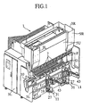
- Fig. 1 is a perspective view showing an exterior of the press brake 1 and the sheet metal apparatus 11 of the first embodiment of the present invention.
- an upper table 5U which may be moved freely up and down is provided in between the upper part front face of the left and right side plates 3L, 3R, and on the lower edge part of this upper table 5U, punch P are fixed by a plurality of intermediate plate 7.
- the upper table 5 may be moved up and down by driving mechanisms 9L, 9R which are placed on the upper part of front faces of the side plates 3L, 3R.
- a lower table 5L is attached on the lower part of the front face of the left and right side plates 3L, 3R and dies D are set free to attach or detach on the upper edge of this lower table 5L.
- a control device 10 that, for instance, controls press brake 1 is provided on the side plate 3L.
- bending process on work W positioned above die D may be made by coactions of the punch P and die D by moving the upper table 5U up and down by the driving mechanisms 9L, 9R.
- a sheet metal support device 11 is provided on the front face of press brake 1 (right side face in Fig. 1).
- left-right linear guide rail 13 is provided in the left-right direction (the elongated direction of the lower table 5L) on the upper part of the front face of table 5L, and on the lower part of the front face a linear guide rail 15 is provided in the left-right direction.
- a pair of base plates 21 are provided, and the spacing thereof is regulated according to the breadth of the work to be bent.
- an up-down linear guide rail 23 is furnished in the up-down direction.
- a screw 27 for up-down movement mechanism is furnished which is supported free to rotate on the bearings 25 furnished at the top and down positions and an up-down servo motor 31 is furnished on the bracket 29 fitted on the lower edge of the base plate 21.
- a belt is wound around in between drive pulley 33 that is fixed on the rotating axis of the up-down servo motor 31 and the driven pulley 35 that is furnished on the lower edge of the screw part 27.
- an up-down slider 39 On the up-down linear guide rail 23, there is provided an up-down slider 39, and nuts 41 are fixed to the up-down slider 39.
- the nuts 41 are moved up and down so as to move the up-down slider 39 up and down.
- a support arm 43 that follows the rise of the bent work W and a rotation servomotor 45 for the rotation mechanisms for rotating this support arm 43.
- a magnet (not shown in the figure) is provided to support the sheet metal (work) W.
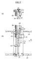
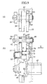
- a rotation servo motor 45 is installed on a bracket 47 which is set up vertically on the up-down slider 39, and has a first gear 53 which is furnished on a rotation driving axis 51 via a reduction gear 49, and a second gear 57 which is an idle gear engaged to this first gear 53 and is free to rotate by bearing 55, and a third gear 59 which is rotated by engagement with this second gear 57.
- the third gear 59 is attached to one of the ends of a first axis 63 as a fixed point by key 61 (refer Fig. 9(b)) and on the other end of the first axis 63, the fourth gear 65 which is a fixed gear is rotatably mounted on the first axis 63 through a bearing 66. Also on the central part of the first axis 63, a rotating axis support plate 67 that is a rotating plate is fixed by key 69 (refer Fig. 9(b)).
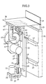
- the fourth gear 65 is a fixed gear that is free to rotate relative to the first axis 63; as it is fixed to the up-down slider 39 by block 71 (refer Fig. 2, Fig. 3), it remains stationary although the first axis 63 is rotating.
- the second axis 73 which acts as the rotation center of the support arm 43 is fixed by a bearing 75 free to rotate and the fifth gear 77 which is a rotation gear is provided on this second axis 73.
- the support arm 43 is fixed to this fifth gear 77 by bolt 79.
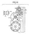
- the sixth gear 83 that is supported free to rotate by the rotation axis support plate 67 by the third axis 81 is provided engaged to both the fourth gear 65 and the fifth gear 77.
- the sixth gear 83 which is axially supported by the third axis 81 on the front face of the rotation axis support plate 67 (front side of the drawing in Fig. 10) and engages with the fixed fourth gear 65 will revolve around the fixed fourth gear 65 while rotating. Therefore the fifth gear 77 engaged with the sixth gear 83 will also rotate around the second axis 73 while revolving around the first axis 63, and the support arm 43 which is fixed to the fifth gear 77 by bolt 79 will rotate centered on the second axis 73 and will follow the rising angle (rotation angle) of the work W.
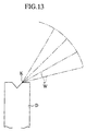
- Fig. 13 shows the movement trajectory of the work during the bending process.
- the support arm 43 may be made to follow the work accurately.
- this invention is not limited to the embodiment of the invention and by appropriate changes, it may be operated by other modes. That is, the control of the servomotor 45 for rotation and the control of the up-down servomotor 31 may be made manually by the eye of the operator. It may be controlled automatically by the control device 10 by linkage with the amount of movement of the upper table 5U that is a ram. In this case, a well-known stroke amount detection device or a bending angle detection device will be used together.
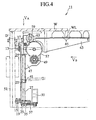
- the shape of the support arm 43 is not determined particularly but, for instance by reference to Fig. 4, in case that work W has a downward bent flange WL, the work W may be supported by a block 85 provided on the support arm 43.
- Fig. 14 is the composition of control data that is formed by the method for forming the control data of the sheet metal bending system of the present invention and shows the control data of a sheet metal part specified by a certain ID.
- This control data is composed of bending process data shown in Fig. 14(a) and follow up data shown in Fig. 14(b); the bending process data and the follow-up data respectively includes a variety of data items for each process number which indicates the bending order which are the bending process order of a plurality of bendings when making sheet metal parts. And these control data are stored in a server provided with a database called the host machine which is connected by LAN and the like so that the control data may be supplied to more than one sheet metal bending system.
- the bending process data for each process number i is provided with the D value which regulates the aimed engagement position of the punch and die in the ith bending process, the L value which regulates the aimed position of the back gauge in the ith bending process, the correction value ⁇ of the D value which is inputted based on the result of trial bendings of the ith bending process, the correction value ⁇ of the L value which is inputted based on the result of trial bending of the ith bending process, the pull back value (PB) which removes the back gauge to the rear when the punch contacts the work in the ith bending process, the contact position (y, z) in the ith bending process, the punch type Pi in the ith bending process, and the die type Di, the value Vi of the V width of the die Di in the ith bending process.
- the D value which regulates the aimed engagement position of the punch and die in the ith bending process the L value which regulates the aimed position of the back gauge in the ith bending process
- the follow-up data for each process number i include whether or not the sheet metal support apparatus is required in the ith bending process, the number of support arms necessary in the ith bending process, the target rotation position ⁇ i of the support arm in the ith bending process, the target height position Hi of the support arm in the ith bending process, whether or not the avoidance-of-interference movement when the punch and die are separated is necessary in the ith bending process and the interference avoidance movement pattern which shows its pattern, the disengagement position Si and the disengagement angle ⁇ i which are the control quantities of the interference avoidance movement in the ith bending process, the follow-up angle revised value ⁇ i based on the result of the trail bending in the ith bending process and the follow-up start height hi which is the height at which the support arm starts to follow-up the rise of the work are included.
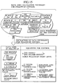
- Fig. 15 is a figure that describes data and formulas for the calculation thereof necessary for the follow-up control of the support arm of the sheet metal support apparatus, which follows the rise of the work.
- the database server which is the aforementioned host machine, data of the punches, data of the dies, data for die holders, data on materials, the D value which regulates the target engagement position of the punch and die and the L value which regulates the target position of the back gauge, which are the control data in each bending, are stored.
- punch data there are data on the size and form for each punch No. which is the ID that specifies the punch type. This includes punch height and form of the punch tip data.
- each die No. which is the ID that specifies the die type. This includes the V width that is the width of the V shaped bending groove formed on the upper surface of the die, the die height and the die shoulder R.
- the die holder data there are data on the die holder height for each die holder no. which is the ID that specifies each die holder type.
- the die height, die holder height, V width, D value, D axis speed inputted by the worker, which are stored in the database server of the host machine, will be regarded as input for the calculation.
- the table follow-up start height which is the height where the sheet metal support apparatus starts to follow the rise of the work will be calculated.
- the target angle position ⁇ which is the inclination of the support arm of the sheet metal support apparatus will be calculated.
- the position H of the target height that is the height of the support arm of the sheet metal support device is calculated based on V width and D axis instruction.
- the movement speed of the inclination and the up-down movement of the support arm of the sheet metal support apparatus are calculated based on V width and the D axis appointed speed.
- Fig. 16 is an outline flow chart that describes the method of generating control data to control the operation of the sheet metal bending system of this invention.
- CAD design data of the sheet metal parts is inputted (S10).
- This may be a three face figure data by a two dimensional CAD or a three dimensional CAD.
- This bending process data includes the process number which is the order of bending in the plurality of bending processes, the D value which regulates the target engagement position of the punch and die of each process number, the L value which regulates the target position of the back gauge, the pull back amount (PB) which is the amount of removal of the back gauge backwards when the punch contacts the work, the contact position (y, z), the punch type Pi and the die type Di.
- the bending process data with this sheet metal part ID conferred is stored in the memory medium of the database server (S60).
- the follow-up data which is the control data which controls the sheet metal support apparatus is prepared (S70), and by storing the follow-up data with this sheet metal parts ID added in the memory medium of the database server (S120) the process will be completed.
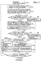
- a bending step that is to be processed is selected (S72). Normally processing is made successively from the first bending process on.
- the size of the work from the bending line during the bending process in the direction of the operator is calculated and the weight is evaluated by reference to the size and the property of the material from the database (S74). If this weight exceeds the designated value, or if the width of the work in the bending line direction exceeds the designated value, it will be judged that the use of the sheet metal support apparatus will be necessary, and, if not, unnecessary (S76).
- the number of support arms to be used will be set (S78) and the bending follow-up data will be prepared (S100).
- the support arm number will be set to be zero (S80).
- the interference avoidance pattern 2 or 3 will be set (S92), the disengagement position S, and the disengagement angle ⁇ will be calculated (S94) and judgment will be made whether the entire bending process is completed or not (S96). If there are bending processes not completed left, transfer will be made to S72. If the entire bending process is completed, procedure is returned.
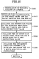
- Fig. 18 is a flow chart which explains the details of the bending follow-up control data preparation routine for S100 of Fig. 17, and is a flow chart to prepare the control data to make the support arm follow-up the rise of the work in the bending process designated by the bending order of the sheet metal parts specified by the sheet metal parts ID.
- the die height is acquired on basis of the die No.
- the die holder height is acquired on basis of the die holder No.
- the value of the die holder height and the die height added to the standard height of the die holder is taken as the follow-up start height H where the support arm of the sheet metal support apparatus starts the follow-up of the rise of the work (S102).
- the die V width is acquired, and the D axis order value of the corresponding bending order is acquired, and based on the die width, D axis order value, the rotation axis order value which rotates the support arm, in other words the aimed rotation position of the support arm is calculated (S104).
- the size and shape of the rotation mechanism of the sheet metal support apparatus 11 will be reflected in the form of the calculation formula.
- the D axis instruction valve, the up-down axis instruction number by which the support arm is moved up and down, in other words the target height position of the support arm will be calculated (S106).
- the measure and form of the rotation mechanism of the sheet metal support apparatus 11 shown in Fig. 1 or Fig. 12 will be reflected on the form of the calculation equation.
- the calculated target rotation position of the support arm does not coincide with the true target rotation position. This is due to the fact that more precisely, the bending part of the work has a curved surface with a certain curvature, and the curvature (or radius of curvature) of this curved surface differ with the work thickness and material quality and the target rotation position of the arm depends on the radius of curvature.
- Also detection of potential discrepancies between the work and the support arm and the computation and storage of the calibrated value of the height and rotated position may be performed a plurality of times at designated angle intervals or designated time intervals in between the start of the bending process and the target rotation position.
- the interference avoidance movement pattern 2 shown in Fig. 19, is a standard movement of avoiding interference between the punch P and work W when the punch P and die D are separated after the bending process, where at the end of the bending process the work W is made to adhere to the support arm 43, and the interference between the punch P and the work W is avoided by increasing the angle of inclination by increasing the rotation angle of the support arm 43 more.
- a work adsorption device 103 such as an electromagnet or a vacuum pad and the like installed on table 101 provided on the upper surface of the support arm 43.
- a work adsorption device 103 such as an electromagnet or a vacuum pad and the like installed on table 101 provided on the upper surface of the support arm 43.
- the support arm 43 on which the work W is adhered by a raising amount S is raised to the disengagement position which is at a smaller raising amount than the rise of the punch P.
- the support arm 43 is rotated to the disengagement angle position ⁇ that is larger than the bending termination angle ⁇ .
- the punch is raised as shown in Fig. 19(d) and returned to initial position of bending.
- the support arm 43 is returned to the follow-up movement starting position. In this way, the punch P and die D may be separated without interference of the punch P and work W.
- the interference avoidance movement pattern 3 shown in Fig. 20 is an optional movement for avoiding interference between punch P and work W when the punch P and die D are separated after bending, where the interference of the punch P and work W is avoided by adhering the work W to the support arm 43 when the bending is finished and sliding the table 101 on the upper face of the support arm 43 parallel to the work support surface.
- the table 101 on the upper face of the support arm 43 is attached so that it may slide on the support arm 43 and also to move the table 101 parallel to the support 43, an air cylinder 105 is provided. Also on the upper face of table 101, a work adsorption device 103 such as an electromagnet or vacuum pad and the like is included.
- the work adhesion device 103 adheres the work W as shown in Fig. 20(a).
- the support arm 43 with the work W adhered is raised to the disengagement position by a rise amount about equal or somewhat smaller than the rise amount of the punch P.
- a cylinder rod 105a is moved forward by sending compressed air through an air tube not shown in the figure to an air cylinder 105.
- the table 101 that is fixed to the front section of the cylinder rod 105 by a bracket 107 will move parallel to the disengagement position with the work W adhered.
- the punch will be raised as shown in Fig. 20(d) to bring it back to the initial position of the bending process.
- the support arm 43 is returned to the follow-up movement start position.
- Hemming also called edge bending is to fold up the edge of the sheet to reinforce the thin sheet and to get rid of the sharp edge to prevent injury.
- a hemming metal mold specific to the hemming is used.
- the punch of the hemming metal mold has, for example, an acute tip angle of about 30°. As shown in Fig.
- the hemming metal mold has a metal mold part 123 which has a V groove (die height hh1) with a bending angle corresponding to the punch, and a metal mold part 125 (die height hh2) to crush and fold in the tip of the work bent with an acute angle, where the die height hh1, hh2 are stored in database corresponding to the hemming metal mold ID No.
- Fig, 21(a) shows the start of the first acute angle bending by the hemming metal mold.
- the follow-up start height position is determined automatically based on the die height hh1 against the die standard position in the bending work process which is one of the hemming metal mold data stored in the database.
- the inclination angle control of the support arm 43 during the bending and control of its height is calculated by the method in accordance with the D value of the V width and D axis movement of the die.
Landscapes
- Engineering & Computer Science (AREA)
- Mechanical Engineering (AREA)
- General Engineering & Computer Science (AREA)
- Manufacturing & Machinery (AREA)
- Quality & Reliability (AREA)
- Physics & Mathematics (AREA)
- General Physics & Mathematics (AREA)
- Automation & Control Theory (AREA)
- Bending Of Plates, Rods, And Pipes (AREA)
Abstract
A computer readable recording medium which stores control
data to control the action of a sheet metal bending system which
is provided with a press brake and a sheet metal support device,
where the press brake is provided with a punch and die which
bends the sheet metal along the bending line by approaching to
and parting from each other, and a back gauge to determine the
position of the sheet metal against the punch and die, the sheet
metal support apparatus is provided with a support arm which
supports the sheet metal and may be rotated freely centered on
the rotation axis which is parallel to the bending axis, the
control data is a control data to control the bending process
which includes a plurality of bending processes to produce sheet
metal parts (parts) with a plurality of bending lines by the
press brake and sheet metal support device by controlling the
approach and parting motion of the punch and die and at least
the rotational motion of the support arm, and the control data
is related to the sheet metal parts ID, and the process number
which specifies the ith bending process of the plurality of
processes which is related to this ID and related to the process
number , the D value which prescribes the target engagement
position of the punch and die in the ith bending process and
related to the process number, the L value which prescribes the
target position of the back gauge in the ith bending process,
and related to the process number, the V width of the die to
be used in the ith bending process, and related to the process
number and the target rotation position of the sheet metal
support which corresponds to the D value which specifies the
target engagement position of the punch and die and the V width
of the die in the ith bending process.
Description
This invention is related to a sheet metal bending system
which includes a press brake and a sheet metal support apparatus
which supports the sheet metal work when the sheet metal is bent
by the press brake and a method to store the control data and
a computer readable memory medium which stores the control data.
In a press brake where bending process of a sheet metal
and the like are performed by combined action of the punch and
die, the rise (or jumping) of the work W accompanying the bending
process occurs with the shoulder K of the die as the revolving
center (refer Fig. 13).
In such a process in course of bending, depending on the
size, sheet thickness, sheet material, the work may be bent due
to the large mass of the jumped part. In order to prevent this
flexure, the worker supported the work or the work was supported
by a sheet metal support device that supported the work
following its jump.
However, if it is made so that the revolving center of
the support arm of this sheet metal support is also on the
shoulder K of the die D, the trajectory may be made the same
as the rise of the work W, but the structure does not allow to
place the rotation axis member as a rotation center at the
shoulder K of the die. Formerly, therefore, a link mechanism
in Japanese patent 1511802 (JP63-61094) by the applicant of the
present patent has been generally used.
Also, the control data of conventional sheet metal
bending systems includes bending process data that control
mainly the press brake and follow-up control data mainly for
control of sheet metal support devices.
The bending process data includes the bending order which
is process order of a plurality of bending processes to be made
on the work, the punch type to be used in each bending process,
the die type, the V breadth of the die, the D value which
prescribes the target engagement position of the punch and the
die in each bending process, and the L value which prescribes
the target position of the back gauge which determines the
position of the work so that the line of the work coincides with
the bending axis of the punch and the die, and the like.
Also, the bending process data is prepared by an automatic
bending programming device called BEND CAM based on, for
instance, three face figures and three dimension CAD data of
sheet metal products and stored in the processing data server
called the host machine. To the host machine, more than one
terminal machine which are press brakes are connected making
it possible to supply processing data from the host to the
terminal machine, and feedback the revised D value, revised L
value which are values revised based on processing data of
actual processing from the terminal machine to the host machine.
Also in the host machine, not only bending process data
but manufacturing machine information, information of metal
molds of punch and die, material information, three-dimensional
figure information which may display three dimensional models
of each sheet metal product by three dimensional CAD, and
unfolded figures and the like of each sheet metal product and
the like are stored.
In the follow-up control data, the necessity of the sheet
metal support apparatus, the number of support arms used, the
necessity of interference avoidance movement between the punch
and the work when the punch and die are to be separated after
the press, and a follow-up timer value which is the period during
which the support arm is to be stopped at the follow-up end
position.
In preparing these follow-up control data, the bending
data is displayed on an input-output device called a press brake
pendant and based on the displayed data the worker judges and
inputs the necessity of the sheet metal support device, the
number of support arms used, the necessity of interference
avoidance movement between the punch and the work when the punch
and die are separated after the press, and the follow-up timer
value to the input device provided on the sheet metal support
device.
However, in the link type sheet metal support device,
there is a problem that a three axis control device, a height
direction control device, a length direction control device and
a rotation angle control device for the die height, V width and
rise of the work will be required making the total unit a complex
and elaborate and costly arrangement.
Also, arranging a large sheet metal support device in
front of the press brake may impair the workability.
Also, there is a problem that in the past the bending
process data for conventional sheet metal bending systems were
stored in the memory device of the host machine and could be
used commonly by each terminal machine connected to the host
machine but for follow-up control data, the follow-up control
data is stored in each sheet metal support device and cannot
be used by other sheet metal support devices.
The object of this invention is, in view of the problems
in the conventional technology, to provide a sheet metal bending
system provided with a sheet metal support device which may
accurately follow-up the rise of the work when bent and a memory
storage from which the stored control data may be read out by
a computer.
The other object of this invention is to provide a read-out
computer memory medium which stores methods of storage of
control data of the sheet metal bending system and control data
of the sheet metal bending system, which enable reuse of
follow-up control data which is the control data used by the
sheet metal support device together with the press brake, by
not only that sheet metal support device but by other sheet metal
support devices. With this arrangement time may be shortened
and the rate of operation of the sheet metal bending system may
be improved.
The present invention is made due to heretofore problems
mentioned above. The sheet metal bending system of the present
invention has a press brake which bends the work along the
bending axis by cooperative action of a punch and die which
approaches and separates from each other and a sheet metal
support device which supports the work being bent by at least
one support arm provided on the front face of this press brake.
And the sheet metal support device has a rotation mechanism
which rotates the support arm centered around the first rotation
axis while rotating the first rotation axis around the second
rotation axis and a linear movement mechanism which moves the
second rotation axis in the direction of the approach and
separation of the punch and die.
In this system, by controlling the rotating mechanism and
the linear movement mechanism, the position of the support arm
in the direction of the approach and separation of the punch
and die and angle of the support arm may be made to coincide
with those of the work being bent.
Also, in the method to generate the control data for
controlling the sheet metal bending system provided with a press
brake and sheet metal support device of the present invention,
the press brake has a punch and a die which bends along the
bending line on the sheet metal by approaching and separating
from each other. And the punch and die has a bending axis. The
press brake is provided with a back gauge that determines the
position of the sheet metal so that the bending axis coincides
with the bending line. The sheet metal support device supports
the sheet metal in front of the press brake and is provided with
a support arm free to rotate around a rotation axis parallel
to the bending axis. The control data is to control the approach
and separation motion of the punch and die in order to control
the approach and separation motion of the punch and die and at
least the rotation movement of the support arm in order to
perform a plurality of bending processes to produce sheet metal
parts (parts) with a plurality of bending lines. And in the
method, the ID of the sheet metal parts are generated; the
bending order which is the order of bending the plurality of
bending lines and of the punch and die type for bending each
bending line is determined; the D value which prescribes the
punch and die target engagement position and generation of the
L value which prescribes the target position of the back gauge
in each bending process is generated; the Z direction position
of the support arm at the start of the bending in each bending
process based on the Z axis direction size of the die to be used
is determined; the target Z axis direction position and the
target rotation position Θof the support arm in each bending
process based on the D value which prescribes the target
engagement position of the punch and die and the V width of the
die (and the thickness of the sheet) are determined; and the
type of the punch and die, and the D value and L value, the height
position of the sheet metal support at the start of the process
and the target height position and the target rotation position
in the bending order and each bending process, are stored in
the memory medium together with the sheet metal parts ID
By the arrangement, according to the method of generating
the control data for controlling the sheet metal bending system
provided with a press brake and a sheet metal support device
of the present invention, not only bending control data such
as D value, L value to control the press brake but also control
data for controlling the sheet metal support apparatus may be
reused on basis of the sheet metal parts ID.
A computer readable recording medium which stores control
data to control the movement of a sheet metal bending system
provided with a press brake and sheet metal support device has
a construction as follows. The press brake is provided with
a punch and die which by mutual approach to and separation from
each other bends the sheet metal along the bending line, and
is provided with a back gauge to position the sheet metal against
the punch and die. And the sheet metal support device supports
the sheet metal in front of the press brake and is provided with
a support arm that may be rotated freely centered on a rotation
axis parallel to the bending axis. The control data is a control
data for controlling the approach and separation movement of
the punch and die and at least the rotation of the support arm
in the bending process which include a plurality of bending
stages to produce sheet metal parts which possess a plurality
of bending lines, and wherein, the control data comprising: an
ID of the sheet metal parts; a process number which is related
to the ID and specifies the ith bending process of a plurality
of bending processes; a D value which is related to the process
number and specifies the target engagement position of the punch
and die in the ith bending process; a L value which is related
to the process number and specifies the target position of the
back gauge in the ith bending process; a V width of the die that
is related to the process number and to be used in the ith bending
process; a target rotation position Θ of the sheet metal support
which is related to the process number and corresponds to the
D value which specifies the target engagement position of the
punch and die and the V width of the die (and the thickness of
the work) in the ith bending process.
With the arrangement, by the computer readable recording
medium which stores the control data to control the action of
the sheet metal bending system provided with the press brake
and sheet metal support device of the present invention, not
only the bending control data such as the D value, L value and
the like but the follow-up control data for controlling the
sheet metal support device may be reused on basis of the sheet
metal parts ID.
It is preferable that the sheet metal support be made free
to move in the direction that the punch and die approach and
separate.
It is preferable that the control data is related to the
process number and possess punch and die data that prescribe
the punch type and die type to be used in the ith bending process.
In the control data, it is preferable that at least one
of the following is provided.
the compensation number δ of the target rotation position of the sheet metal support in the ith bending process, which number is linked to the process number;
the initial position of the sheet metal support in the ith bending process, which position is linked to the process number;
the number (including zero) of sheet metal supports in the ith bending process, which number is linked to the process number;
the interference avoidance motion pattern of the sheet metal support in the ith bending process, which is linked to the process number, which pattern is linked to the process number; and
the disengagement position S and the disengagement angle δ of the sheet metal support in the ith bending process, which position and angle are linked to the process number.
the compensation number δ of the target rotation position of the sheet metal support in the ith bending process, which number is linked to the process number;
the initial position of the sheet metal support in the ith bending process, which position is linked to the process number;
the number (including zero) of sheet metal supports in the ith bending process, which number is linked to the process number;
the interference avoidance motion pattern of the sheet metal support in the ith bending process, which is linked to the process number, which pattern is linked to the process number; and
the disengagement position S and the disengagement angle δ of the sheet metal support in the ith bending process, which position and angle are linked to the process number.
Fig. 1 is a perspective view showing an exterior of the
press brake 1 and the sheet metal apparatus 11 of the first
embodiment of the present invention.
In this press brake 1, an upper table 5U which may be moved
freely up and down is provided in between the upper part front
face of the left and right side plates 3L, 3R, and on the lower
edge part of this upper table 5U, punch P are fixed by a plurality
of intermediate plate 7. The upper table 5 may be moved up and
down by driving mechanisms 9L, 9R which are placed on the upper
part of front faces of the side plates 3L, 3R.
Also, a lower table 5L is attached on the lower part of
the front face of the left and right side plates 3L, 3R and dies
D are set free to attach or detach on the upper edge of this
lower table 5L. On the side plate 3L, a control device 10 that,
for instance, controls press brake 1 is provided.
With the arrangement, bending process on work W
positioned above die D may be made by coactions of the punch
P and die D by moving the upper table 5U up and down by the driving
mechanisms 9L, 9R.
With reference to Figs. 2-10 in addition to Fig. 1, a sheet
metal support device 11 is provided on the front face of press
brake 1 (right side face in Fig. 1). On this sheet metal support
device 11, left-right linear guide rail 13 is provided in the
left-right direction (the elongated direction of the lower
table 5L) on the upper part of the front face of table 5L, and
on the lower part of the front face a linear guide rail 15 is
provided in the left-right direction.
On the left-right slider 17 which may move freely along
the linear guide rail 13 and the roller 19 which rolls along
the linear guide rail 15, a pair of base plates 21 (only one
of the units is shown in Figs. 2-10) are provided, and the spacing
thereof is regulated according to the breadth of the work to
be bent.
On the front face of each base plate 21, an up-down linear
guide rail 23 is furnished in the up-down direction. Also on
the front face of 21, a screw 27 for up-down movement mechanism
is furnished which is supported free to rotate on the bearings
25 furnished at the top and down positions and an up-down servo
motor 31 is furnished on the bracket 29 fitted on the lower edge
of the base plate 21. A belt is wound around in between drive
pulley 33 that is fixed on the rotating axis of the up-down servo
motor 31 and the driven pulley 35 that is furnished on the lower
edge of the screw part 27.
On the up-down linear guide rail 23, there is provided
an up-down slider 39, and nuts 41 are fixed to the up-down slider
39. Thus, by rotating the screw part 27 by the up-down
servomotor 31, the nuts 41 are moved up and down so as to move
the up-down slider 39 up and down.
On the front face of the up-down slider 39, there is a
support arm 43 that follows the rise of the bent work W and a
rotation servomotor 45 for the rotation mechanisms for rotating
this support arm 43. On the support arm 43, a magnet (not shown
in the figure) is provided to support the sheet metal (work)
W.
By referring mainly to Figs. 9(a), (b), a rotation servo
motor 45 is installed on a bracket 47 which is set up vertically
on the up-down slider 39, and has a first gear 53 which is
furnished on a rotation driving axis 51 via a reduction gear
49, and a second gear 57 which is an idle gear engaged to this
first gear 53 and is free to rotate by bearing 55, and a third
gear 59 which is rotated by engagement with this second gear
57.
The third gear 59 is attached to one of the ends of a first
axis 63 as a fixed point by key 61 (refer Fig. 9(b)) and on the
other end of the first axis 63, the fourth gear 65 which is a
fixed gear is rotatably mounted on the first axis 63 through
a bearing 66. Also on the central part of the first axis 63,
a rotating axis support plate 67 that is a rotating plate is
fixed by key 69 (refer Fig. 9(b)).
Therefore, when the rotation servomotor 45 is driven, the
first gear 53 will rotate, and by the second gear 57 the third
gear 59 will rotate and the first axis 63 will rotate as one
body and also the rotation axis support plate 67 will rotate
as one body by the key 69. Here the fourth gear 65 is a fixed
gear that is free to rotate relative to the first axis 63; as
it is fixed to the up-down slider 39 by block 71 (refer Fig.
2, Fig. 3), it remains stationary although the first axis 63
is rotating.
On the lower edge part of the rotating axis support plate
67 in Fig. 9(b), the second axis 73 which acts as the rotation
center of the support arm 43 is fixed by a bearing 75 free to
rotate and the fifth gear 77 which is a rotation gear is provided
on this second axis 73. The support arm 43 is fixed to this
fifth gear 77 by bolt 79.
Referring to Fig. 10, in between the fourth gear 65 and
the fifth gear 77, the sixth gear 83 that is supported free to
rotate by the rotation axis support plate 67 by the third axis
81 is provided engaged to both the fourth gear 65 and the fifth
gear 77.
Next, the action of the sheet metal support apparatus 11
will be explained with reference mainly to Fig. 9(a), (b). By
driving the rotation servomotor 45, the first gear 53, the
second gear 57, the third gear 59 will be rotated and the first
axis 63 will rotate. Thereby the rotation axis support plate
67 that is integrated to the first axis 63 by key 69 will rotate.
When the rotation axis support plate 67 rotates, the sixth
gear 83 which is axially supported by the third axis 81 on the
front face of the rotation axis support plate 67 (front side
of the drawing in Fig. 10) and engages with the fixed fourth
gear 65 will revolve around the fixed fourth gear 65 while
rotating. Therefore the fifth gear 77 engaged with the sixth
gear 83 will also rotate around the second axis 73 while
revolving around the first axis 63, and the support arm 43 which
is fixed to the fifth gear 77 by bolt 79 will rotate centered
on the second axis 73 and will follow the rising angle (rotation
angle) of the work W.
As described already, the rise of the work W accompanying
the bending process arises by rotation centered on the shoulder
part K of the die D. Fig. 13 shows the movement trajectory of
the work during the bending process.
With reference to Fig. 11, the trajectory of the rise of
the work W and the trajectory of the second axis 73 of the fifth
gear 77 that is the rotation center of the support arm 43 will
be described. The angle shown in the figure is the rotation
angle of the work W and also the inclination angle of the support
arm 43,
As shown in Fig. 11, when the rotation angle of the work
W increases slowly anticlockwise (arrow direction in Fig. 11)
from O degree, the second axis 73 which is the revolution center
rotates centered on the fourth gear 65 and the first axis 63.
Consequently, as the support arm 43 rotates with the
center on the second axis 73, an arbitrary point P on the support
arm will always be at the same position in the back and forth
direction as that of the rise trajectory of the work W (that
is, it is a equal distance from the die center).
Therefore, as shown in Fig. 12, by moving the up-down
slider 39 up and down by the up-down servo motor 31, screw part
27 and nut part 41 to move up and down the support arm 43 by
an amount corresponding to the bending angle of the work W, the
support arm 43 may be made to follow the work accurately.
From the above results, in the ascent trajectory of the
work from the start of the ascent to the bending angle of near
30 degrees, the moving distance in the back and forth direction
is small; thus, by revolving the second axis 73 which is the
rotation center in the direction away from the die D, the follow
up plate may be moved in a trajectory closer to the ascent
trajectory of the work W compared to when the rotation center
is fixed. Thus the work may be supported properly by a simple
and compact structure. Also, cost down of the apparatus may
be contrived.
Also, this invention is not limited to the embodiment of
the invention and by appropriate changes, it may be operated
by other modes. That is, the control of the servomotor 45 for
rotation and the control of the up-down servomotor 31 may be
made manually by the eye of the operator. It may be controlled
automatically by the control device 10 by linkage with the
amount of movement of the upper table 5U that is a ram. In this
case, a well-known stroke amount detection device or a bending
angle detection device will be used together.
Also the shape of the support arm 43 is not determined
particularly but, for instance by reference to Fig. 4, in case
that work W has a downward bent flange WL, the work W may be
supported by a block 85 provided on the support arm 43.
Next, by reference to Figs. 14-18, the method of
generating control data of the sheet metal bending system of
the present invention will be explained.
Fig. 14 is the composition of control data that is formed
by the method for forming the control data of the sheet metal
bending system of the present invention and shows the control
data of a sheet metal part specified by a certain ID.
This control data is composed of bending process data
shown in Fig. 14(a) and follow up data shown in Fig. 14(b); the
bending process data and the follow-up data respectively
includes a variety of data items for each process number which
indicates the bending order which are the bending process order
of a plurality of bendings when making sheet metal parts. And
these control data are stored in a server provided with a
database called the host machine which is connected by LAN and
the like so that the control data may be supplied to more than
one sheet metal bending system.
The bending process data for each process number i is
provided with the D value which regulates the aimed engagement
position of the punch and die in the ith bending process, the
L value which regulates the aimed position of the back gauge
in the ith bending process, the correction value α of the D
value which is inputted based on the result of trial bendings
of the ith bending process, the correction value β of the L
value which is inputted based on the result of trial bending
of the ith bending process, the pull back value (PB) which
removes the back gauge to the rear when the punch contacts the
work in the ith bending process, the contact position (y, z)
in the ith bending process, the punch type Pi in the ith bending
process, and the die type Di, the value Vi of the V width of
the die Di in the ith bending process.
The follow-up data for each process number i include
whether or not the sheet metal support apparatus is required
in the ith bending process, the number of support arms necessary
in the ith bending process, the target rotation position Θi
of the support arm in the ith bending process, the target height
position Hi of the support arm in the ith bending process,
whether or not the avoidance-of-interference movement when the
punch and die are separated is necessary in the ith bending
process and the interference avoidance movement pattern which
shows its pattern, the disengagement position Si and the
disengagement angle δ i which are the control quantities of the
interference avoidance movement in the ith bending process, the
follow-up angle revised value i based on the result of the
trail bending in the ith bending process and the follow-up start
height hi which is the height at which the support arm starts
to follow-up the rise of the work are included.
Fig. 15 is a figure that describes data and formulas for
the calculation thereof necessary for the follow-up control of
the support arm of the sheet metal support apparatus, which
follows the rise of the work.
In the database server which is the aforementioned host
machine, data of the punches, data of the dies, data for die
holders, data on materials, the D value which regulates the
target engagement position of the punch and die and the L value
which regulates the target position of the back gauge, which
are the control data in each bending, are stored.
In the punch data, there are data on the size and form
for each punch No. which is the ID that specifies the punch type.
This includes punch height and form of the punch tip data.
Similarly, in the die data, there are data on the size
and form for each die No. which is the ID that specifies the
die type. This includes the V width that is the width of the
V shaped bending groove formed on the upper surface of the die,
the die height and the die shoulder R.
Similarly, in the die holder data, there are data on the
die holder height for each die holder no. which is the ID that
specifies each die holder type.
Also in the material data, there are data on sheet
thickness, bending length, material property, specific gravity
or the weight per unit area for each variety of sheet metal
material in correspondence to the material classification
symbol.
And in the method for preparing data for controlling the
action of the sheet metal bending system which is provided with
the press brake and a sheet metal support apparatus of the
present invention, the die height, die holder height, V width,
D value, D axis speed inputted by the worker, which are stored
in the database server of the host machine, will be regarded
as input for the calculation.
On basis of the die height and die holder height, the table
follow-up start height which is the height where the sheet metal
support apparatus starts to follow the rise of the work will
be calculated.
This relation may be described by the equation,
f1 (die height, die holder height) = start height of table
follow up.
Also, based on the V width and D axis instructions, the
target angle position Θwhich is the inclination of the support
arm of the sheet metal support apparatus will be calculated.
This relation may be described by the equation,
f2 (V width, D axis instruction) = target rotation
position Θ of the support arm.
Also, the position H of the target height that is the
height of the support arm of the sheet metal support device is
calculated based on V width and D axis instruction.
This relation may be described by the equation,
f3 (V width, D axis instruction = target height position
H of the support arm.
Also the movement speed of the inclination and the up-down
movement of the support arm of the sheet metal support apparatus
are calculated based on V width and the D axis appointed speed.
This relation may be described by the equation,
f4 (V width, D axis appointed speed) = movement speed of
the rotation axis and up-down axis.
Next, the method of generating the control data to control
the movement of the sheet metal bending system of this invention
will be explained with reference to the flow chart of Fig. 16
or Fig. 18.
Fig. 16 is an outline flow chart that describes the method
of generating control data to control the operation of the sheet
metal bending system of this invention.
In Fig. 16, first the CAD design data of the sheet metal
parts is inputted (S10). This may be a three face figure data
by a two dimensional CAD or a three dimensional CAD.
Next, based on the CAD data, the unfolded figure and
three-dimensional figure are drawn-up (S20). Next the bending
process data is prepared (S30). This bending process data
includes the process number which is the order of bending in
the plurality of bending processes, the D value which regulates
the target engagement position of the punch and die of each
process number, the L value which regulates the target position
of the back gauge, the pull back amount (PB) which is the amount
of removal of the back gauge backwards when the punch contacts
the work, the contact position (y, z), the punch type Pi and
the die type Di.
Next, bending simulation for each bending process is made
(S40), and judgment is made whether or not in the bending process
the work and the punch or one part and another part of the work
interfere with each other (S50). If there is bending
interference, by returning to the bending process data
formation step S30, the bending process is revised so that
interference is avoided.
If there is no interference, the bending process data with
this sheet metal part ID conferred is stored in the memory medium
of the database server (S60).
Next, the follow-up data which is the control data which
controls the sheet metal support apparatus is prepared (S70),
and by storing the follow-up data with this sheet metal parts
ID added in the memory medium of the database server (S120) the
process will be completed.
Next by referring to Fig. 17, the preparation of the
follow-up data that is step S70 in Fig. 16 will be described
in detail. First, a bending step that is to be processed is
selected (S72). Normally processing is made successively from
the first bending process on. Next the size of the work from
the bending line during the bending process in the direction
of the operator is calculated and the weight is evaluated by
reference to the size and the property of the material from the
database (S74). If this weight exceeds the designated value,
or if the width of the work in the bending line direction exceeds
the designated value, it will be judged that the use of the sheet
metal support apparatus will be necessary, and, if not,
unnecessary (S76).
If it is judged that the sheet metal support apparatus
is necessary, on basis of the work size, work weight and metal
mold station arrangement, the number of support arms to be used
will be set (S78) and the bending follow-up data will be prepared
(S100).
If it is judged that there is no need for the sheet metal
support apparatus, the support arm number will be set to be zero
(S80).
Next, based on the shape data stored in the database, and
the bent shape by the bending process, it is judged whether the
punch and the work interfere with each other when the punch and
die separate after the bending process (S82). If there is no
interference, the interference avoidance movement pattern 1
will be set (S86) and procedure will proceed to S96 that will
be described later.
If it is judged that interference will occur in S82, it
will be judged whether the sheet metal support apparatus is
provided with the option device for interference avoidance
(S84). If the option is not set up, the interference avoidance
movement pattern 2 which will be mentioned later by referring
to Fig. 19 will be set up (S88), and the disengagement angle
δ will be evaluated (S90) and will proceed to step S96.
If an option is set up in the judgment of S84, the
interference avoidance pattern 2 or 3 will be set (S92), the
disengagement position S, and the disengagement angle δ will
be calculated (S94) and judgment will be made whether the entire
bending process is completed or not (S96). If there are bending
processes not completed left, transfer will be made to S72. If
the entire bending process is completed, procedure is returned.
Fig. 18 is a flow chart which explains the details of the
bending follow-up control data preparation routine for S100 of
Fig. 17, and is a flow chart to prepare the control data to make
the support arm follow-up the rise of the work in the bending
process designated by the bending order of the sheet metal parts
specified by the sheet metal parts ID.
First, by reference to the database of the host machine,
the die height is acquired on basis of the die No., the die holder
height is acquired on basis of the die holder No. and the value
of the die holder height and the die height added to the standard
height of the die holder is taken as the follow-up start height
H where the support arm of the sheet metal support apparatus
starts the follow-up of the rise of the work (S102).
Next by reference to the database, the die V width is
acquired, and the D axis order value of the corresponding
bending order is acquired, and based on the die width, D axis
order value, the rotation axis order value which rotates the
support arm, in other words the aimed rotation position of
the support arm is calculated (S104). Needless to say, the size
and shape of the rotation mechanism of the sheet metal support
apparatus 11 will be reflected in the form of the calculation
formula.
Next based on the die width, the D axis instruction valve,
the up-down axis instruction number by which the support arm
is moved up and down, in other words the target height position
of the support arm will be calculated (S106). Here, similar
to the target rotation position, the measure and form of the
rotation mechanism of the sheet metal support apparatus 11 shown
in Fig. 1 or Fig. 12 will be reflected on the form of the
calculation equation.
Next, based on the die width, the inputted D axis assigned
speed, the rotation axis speed, the up-down axis speed which
moves the support arm up and down will be calculated (S108) and
proceeds to return.
Now there are cases where the calculated target rotation
position of the support arm does not coincide with the true
target rotation position. This is due to the fact that more
precisely, the bending part of the work has a curved surface
with a certain curvature, and the curvature (or radius of
curvature) of this curved surface differ with the work thickness
and material quality and the target rotation position of the
arm depends on the radius of curvature.
Therefore after preparing the control data based on Fig.
16, it is preferable to perform a trial bending based on this
control data, and to detect potential discrepancies between the
work and the support arm at the target rotation position of the
work. And in case discrepancies occur between the work and
support arm at the target rotation position, in order to
compensate this discrepancy it is desirable to calibrate at
least either the target position or the target rotation position
and store the calibrated value in the database.
Also detection of potential discrepancies between the
work and the support arm and the computation and storage of the
calibrated value of the height and rotated position may be
performed a plurality of times at designated angle intervals
or designated time intervals in between the start of the bending
process and the target rotation position.
Next, the interference avoidance motion pattern 2 and 3
will be explained with reference to Fig. 19 and Fig. 20.
The interference avoidance movement pattern 2 shown in
Fig. 19, is a standard movement of avoiding interference between
the punch P and work W when the punch P and die D are separated
after the bending process, where at the end of the bending
process the work W is made to adhere to the support arm 43, and
the interference between the punch P and the work W is avoided
by increasing the angle of inclination by increasing the
rotation angle of the support arm 43 more.
First as shown in Fig. 19(a) after the bending, the work
W is adhered by a work adsorption device 103 such as an
electromagnet or a vacuum pad and the like installed on table
101 provided on the upper surface of the support arm 43. Next,
as shown in Fig. 19(b), while raising the punch P, the support
arm 43 on which the work W is adhered by a raising amount S is
raised to the disengagement position which is at a smaller
raising amount than the rise of the punch P. By this raising
of the punch P and the raising of the support arm, a spacing
by which the rotation of the work W does not interfere with punch
P and die D will be obtained.
Next, as shown in Fig. 19(c), the support arm 43 is rotated
to the disengagement angle position δ that is larger than the
bending termination angle Θ. At this state, the punch is
raised as shown in Fig. 19(d) and returned to initial position
of bending. Finally as shown in Fig. 19(e), the support arm
43 is returned to the follow-up movement starting position. In
this way, the punch P and die D may be separated without
interference of the punch P and work W.
The interference avoidance movement pattern 3 shown in
Fig. 20 is an optional movement for avoiding interference
between punch P and work W when the punch P and die D are separated
after bending, where the interference of the punch P and work
W is avoided by adhering the work W to the support arm 43 when
the bending is finished and sliding the table 101 on the upper
face of the support arm 43 parallel to the work support surface.
To do so, as shown in Fig. 20(a), the table 101 on the
upper face of the support arm 43 is attached so that it may slide
on the support arm 43 and also to move the table 101 parallel
to the support 43, an air cylinder 105 is provided. Also on
the upper face of table 101, a work adsorption device 103 such
as an electromagnet or vacuum pad and the like is included.
When the bending process is finished, the work adhesion
device 103 adheres the work W as shown in Fig. 20(a). Next,
as shown in Fig. 20(b), while raising the punch P, the support
arm 43 with the work W adhered is raised to the disengagement
position by a rise amount about equal or somewhat smaller than
the rise amount of the punch P. By this rise of the punch P
and the rise of the support arm 43, a spacing will be given
whereby the work W will not interfere with the punch P and D
when moving parallel to the table face.
Next, as shown in Fig. 20(c), a cylinder rod 105a is moved
forward by sending compressed air through an air tube not shown
in the figure to an air cylinder 105. The table 101 that is
fixed to the front section of the cylinder rod 105 by a bracket
107 will move parallel to the disengagement position with the
work W adhered.
At this stage, the punch will be raised as shown in Fig.
20(d) to bring it back to the initial position of the bending
process. Finally, as shown in Fig. 20(e), the support arm 43
is returned to the follow-up movement start position. By this
way, the interference between the punch P and work W may be
avoided when the punch P and die D is separated.
Next by reference to Fig. 21, the automatic determination
of hemming movement that is an example of application of the
present invention will be described. Hemming, also called edge
bending is to fold up the edge of the sheet to reinforce the
thin sheet and to get rid of the sharp edge to prevent injury.
A hemming metal mold specific to the hemming is used. The punch
of the hemming metal mold has, for example, an acute tip angle
of about 30°. As shown in Fig. 21(a), the hemming metal mold
has a metal mold part 123 which has a V groove (die height hh1)
with a bending angle corresponding to the punch, and a metal
mold part 125 (die height hh2) to crush and fold in the tip of
the work bent with an acute angle, where the die height hh1,
hh2 are stored in database corresponding to the hemming metal
mold ID No.
Fig, 21(a) shows the start of the first acute angle bending
by the hemming metal mold. Here, in preparing the control data
of the height of the support arm 43 of the sheet metal support
apparatus, the follow-up start height position is determined
automatically based on the die height hh1 against the die
standard position in the bending work process which is one of
the hemming metal mold data stored in the database.
Next, as shown in Fig. 21(b) the inclination angle control
of the support arm 43 during the bending and control of its height
is calculated by the method in accordance with the D value of
the V width and D axis movement of the die.
Next, when bending is ended, the inclination of the
support arm 43 returns to the horizontal position as shown in
Fig. 21(c) whereas the position of the height that the support
arm 43 returns to is determined as the height hh2 of the die
metal mold surface for the folding at the die standard position.
After this, the worker, as shown in Fig. 21(d), pushes
the work W placed on the upper surface of the support arm 43,
which has been made the same height as the die height hh2, into
the fold up die 125 and executes the fold up press.
Claims (17)
- A computer readable recording medium which stores control data for controlling the action of a sheet metal bending system provided with a press brake and a sheet metal support device, the control data comprising:an ID of the sheet metal parts;a process number that is related to the ID and specifies the ith bending process of a plurality of bending processes;a D value which is related to the process number and specifies the target engagement position of the punch and die in the ith bending process;a L value that is related to the process number and specifies the target position of the back gauge in the ith bending process;a V width of the die that is related to the process number and to be used in the ith bending process;a target rotation position Θ of the sheet metal support which is related to the process number and corresponds to the D value which specifies the target engagement position of the punch and die and the V width of the die in the ith bending process.
- A sheet metal bending system which is provided with a press brake which bends a work along the bending axis by collaborative action of a punch and die which mutually approach and part from each other, and a sheet metal support device which supports the work being bent by at least one support arm provided on the front face of the press brake,
characterized in that the sheet metal support apparatus rotates the support arm around a first rotation axis which is parallel to the bending axis; and on the other hand is provided with a revolution mechanism to revolve the first rotation axis around a second rotation axis and a linear movement mechanism to move the second rotation axis in the approach and separation direction of the punch and die; and makes the position of the support arm in the direction for the punch and die to move toward and away from each other and the angle of the support arm coincide with those of work being bent. - A sheet metal bending system as described in claim 2 characterized in that the revolving mechanism is provided with a fixed gear provided on the second rotation axis so that it may not rotate, and a revolving gear which is engaged directly or indirectly to this fixed gear and rotates around the second rotation axis and at the same time by this rotation revolves around the second rotation axis together with the revolving plate.
- The sheet metal bending system as described in claim 3 characterized by provision of a control device which instructs the height of the support arm to coincide with the height of the work being bent by controlling the linear movement mechanism together with controlling the rotation mechanism so that the inclination angle of the support arm coincides with the bending angle of the work being bent.
- A sheet metal bending system according to claim 2 wherein a plurality of said support arms is provided parallel to the bending line with adjustable spacings.
- A method of generating control data to control the action of the sheet metal bending system which is provided with a press brake and a sheet metal support apparatus,
wherein the press brake is provided with a punch and die which bend along the bending line on the sheet metal by mutually approaching and parting from each other, where the punch and die possess a bending axis; and a back gauge to position the sheet metal so that the bending axis coincides with the bending line; and
the sheet metal support device supports the sheet metal in front of the press brake, and is provided with a support arm which may be freely rotated around the rotating axis parallel to the bending axis; and
the control data is a control data for controlling the approach and separation movement of the punch and die and at least the rotation of the support arm in the bending process which include a plurality of bending stages to produce sheet metal parts which possess a plurality of bending lines; and wherein,
the method includes the steps of:generation of the sheet metal parts ID;determination of the bending order that is the order of bending the plurality of bending lines and of the punch and die type for bending each bending line;generation of the D value that prescribes the punch and die target engagement position and generation of the L value that prescribes the target position of the back gauge in each bending process;determination of the Z direction position of the support arm at the start of the bending in each bending process based on the Z-axis direction size of the die to be used;determination of the target Z axis direction position and the target rotation position Θ of the support arm in each bending process based on the D value which prescribes the target engagement position of the punch and die and the V width of the die. - The method according to claim 6 where the sheet metal support is movable in the Z axis direction in which the punch and die move toward and away from each other.
- The method of claim 7 wherein the Z-axis direction is the vertical direction.
- The method of claim 6 further including the process of the determination of the number of sheet metal supports (including zero) in each bending process.
- The method of claim 9 wherein in order to determine the number of sheet metal supports, at least one of the items of the work size, the flange protrusion length in the front side of the work machine, the sheet thickness and quality of material is considered.
- The method of claim 6 wherein a trial bending of a sheet metal by the bending system is carried out based on the determined data, and when discrepancy occurs in the movement of the sheet metal support and the movement of the work being bent in the bending, the revision of the target height position and target rotation position of the sheet metal support and storage of the revised values are made.
- The method of claim 6 wherein a determination of whether in each bending process the punch may be separated freely from work or not at the target engagement position is made, and if it is not separable, the movement pattern of the punch or die and the movement pattern of the sheet metal support to make it separable are determined.
- The method of claim 6 wherein the type of the punch and die, and the D value and L value, the height position of the sheet metal support at the start of the process and the target height position and the target rotation position in the bending order and in each bending process are stored in the memory medium together with the sheet metal parts ID.
- A method according to claim 6, wherein the method includes a process for preparing at least one of unfolded figure or three dimensional figure of the parts based on the initial CAD data of the parts.
- A method according to claim 14 where the control data is prepared on basis of the unfolded figure or the 3 dimensional figure.
- A method according to claim 12, where the movement pattern includes the disengagement position S and the disengagement angle δ.
- A computer readable recording medium which stores control data to control the movement of a sheet metal bending system provided with a press brake and sheet metal support device wherein,
the press brake is provided with a punch and die which by mutual approach to and separation from each other bends the sheet metal along the bending line,
and is provided with a back gauge to position the sheet metal against the punch and die,
the sheet metal support device supports the sheet metal in front of the press brake and is provided with a support arm which may be rotated freely centered on a rotation axis parallel to the bending axis,
the control data is a control data for controlling the approach and separation movement of the punch and die and at least the rotation of the support arm in the bending process which include a plurality of bending stages to produce sheet metal parts which possess a plurality of bending lines, and wherein,
the control data comprising:an ID of the sheet metal parts;a process number that is related to the ID and specifies the ith bending process of a plurality of bending processes;a D value which is related to the process number and specifies the target engagement position of the punch and die in the ith bending process;a L value that is related to the process number and specifies the target position of the back gauge in the ith bending process;a V width of the die that is related to the process number and to be used in the ith bending process;a target rotation position Θ of the sheet metal support which is related to the process number and corresponds to the D value which specifies the target engagement position of the punch and die and the V width of the die in the ith bending process.
Applications Claiming Priority (3)
| Application Number | Priority Date | Filing Date | Title |
|---|---|---|---|
| JP19918599 | 1999-07-13 | ||
| JP19918599 | 1999-07-13 | ||
| PCT/JP2000/004703 WO2001003864A1 (en) | 1999-07-13 | 2000-07-13 | Sheet metal bending system comprising press brake and sheet metal support device, control data creating method therefor, and computer-readable storage medium where the control data is stored |
Publications (2)
| Publication Number | Publication Date |
|---|---|
| EP1203625A1 true EP1203625A1 (en) | 2002-05-08 |
| EP1203625A4 EP1203625A4 (en) | 2008-10-22 |
Family
ID=16403562
Family Applications (1)
| Application Number | Title | Priority Date | Filing Date |
|---|---|---|---|
| EP00946297A Withdrawn EP1203625A4 (en) | 1999-07-13 | 2000-07-13 | Sheet metal bending system comprising press brake and sheet metal support device, control data creating method therefor, and computer-readable storage medium where the control data is stored |
Country Status (4)
| Country | Link |
|---|---|
| US (1) | US6823708B1 (en) |
| EP (1) | EP1203625A4 (en) |
| JP (1) | JP3790161B2 (en) |
| WO (1) | WO2001003864A1 (en) |
Cited By (1)
| Publication number | Priority date | Publication date | Assignee | Title |
|---|---|---|---|---|
| CN105127253A (en) * | 2015-09-10 | 2015-12-09 | 安徽省科昌机械制造有限公司 | Automatic bending production line for kitchen cabinet sheet metal parts |
Families Citing this family (12)
| Publication number | Priority date | Publication date | Assignee | Title |
|---|---|---|---|---|
| AU2012201353B2 (en) * | 2002-06-28 | 2012-04-19 | Dolby Laboratories Licensing Corporation | Improved interpolation of video compression frames |
| JP5060742B2 (en) * | 2005-06-28 | 2012-10-31 | 株式会社アマダ | Press machine, crank press machine, and vibration processing method |
| JP5108260B2 (en) * | 2006-07-06 | 2012-12-26 | 株式会社アマダ | Method and apparatus for utilizing bending machine mold layout |
| JP2009190058A (en) * | 2008-02-14 | 2009-08-27 | Murata Mach Ltd | Press brake system |
| EP2199956A1 (en) * | 2008-12-18 | 2010-06-23 | Siemens Aktiengesellschaft | Method and system for managing results of an analysis process on objects handled along a technical process line |
| AT515296B1 (en) * | 2014-03-19 | 2015-08-15 | Trumpf Maschinen Austria Gmbh | Bending aid for a press brake |
| JP6272122B2 (en) * | 2014-04-23 | 2018-01-31 | 株式会社アマダホールディングス | Guide rail fixing structure for press brake |
| US10857581B2 (en) * | 2016-11-15 | 2020-12-08 | Accurpress America Inc. | Machine for bending metal including an adjustable backgauge |
| JP7441054B2 (en) * | 2019-07-09 | 2024-02-29 | コマツ産機株式会社 | Follower for bending machines |
| JP7332366B2 (en) * | 2019-07-09 | 2023-08-23 | コマツ産機株式会社 | Tracking device for bending machines |
| NL2024104B1 (en) * | 2019-10-25 | 2021-02-23 | Morris Solutions B V | Press brake and method for operating therefor |
| CN115301778B (en) * | 2022-10-11 | 2023-02-10 | 扬州宇鑫智能科技有限公司 | Plate bending machine |
Family Cites Families (13)
| Publication number | Priority date | Publication date | Assignee | Title |
|---|---|---|---|---|
| AT384759B (en) * | 1986-06-16 | 1988-01-11 | Haemmerle Ag | METHOD FOR CONTROLLING A LIFTING PREST ON TIN PRESSES |
| US4741862A (en) | 1986-08-22 | 1988-05-03 | Dow Corning Corporation | Zeolite built detergent compositions |
| JP2534205B2 (en) * | 1987-07-24 | 1996-09-11 | ヤマザキマザック株式会社 | Follower for press brake |
| JP2655851B2 (en) * | 1987-11-06 | 1997-09-24 | 株式会社アマダ | Plate support device for press brake |
| DE3919208C1 (en) | 1989-06-13 | 1990-10-31 | Eduard Kuesters Maschinenfabrik Gmbh & Co Kg, 4150 Krefeld, De | |
| JPH0324313U (en) * | 1989-07-19 | 1991-03-13 | ||
| JP3507099B2 (en) | 1993-05-28 | 2004-03-15 | 株式会社アマダ | Press brake work tracking device |
| WO1996001706A1 (en) * | 1994-07-08 | 1996-01-25 | Amada Company, Limited | Method for bending with press brake and press brake for use therein |
| JP3509964B2 (en) * | 1994-11-22 | 2004-03-22 | 株式会社アマダ | Operation recording method and recording device for NC processing machine |
| JPH08187515A (en) | 1994-12-29 | 1996-07-23 | Nisshinbo Ind Inc | Program preparing device for robot handling material for plate bending machine |
| DE29512330U1 (en) * | 1995-07-31 | 1995-09-28 | Siemens AG, 80333 München | Product data storage facility |
| US5983688A (en) * | 1996-07-08 | 1999-11-16 | Anzai; Tetsuya | Method and apparatus for displaying die layout in press brake and for checking interference |
| IT1294998B1 (en) * | 1997-09-09 | 1999-04-27 | Salvagnini Italia Spa | PROCEDURE FOR THE AUTOMATIC GENERATION OF A SEQUENCE OF COMMANDS FOR SHEETS FOLDING MACHINE |
-
2000
- 2000-07-13 US US10/030,622 patent/US6823708B1/en not_active Expired - Lifetime
- 2000-07-13 WO PCT/JP2000/004703 patent/WO2001003864A1/en not_active Ceased
- 2000-07-13 JP JP2001509326A patent/JP3790161B2/en not_active Expired - Fee Related
- 2000-07-13 EP EP00946297A patent/EP1203625A4/en not_active Withdrawn
Cited By (2)
| Publication number | Priority date | Publication date | Assignee | Title |
|---|---|---|---|---|
| CN105127253A (en) * | 2015-09-10 | 2015-12-09 | 安徽省科昌机械制造有限公司 | Automatic bending production line for kitchen cabinet sheet metal parts |
| CN105127253B (en) * | 2015-09-10 | 2017-03-15 | 安徽省科昌机械制造股份有限公司 | A kind of automatic bending production line of kitchen cabinet sheet metal component |
Also Published As
| Publication number | Publication date |
|---|---|
| EP1203625A4 (en) | 2008-10-22 |
| JP3790161B2 (en) | 2006-06-28 |
| US6823708B1 (en) | 2004-11-30 |
| WO2001003864A1 (en) | 2001-01-18 |
Similar Documents
| Publication | Publication Date | Title |
|---|---|---|
| US6823708B1 (en) | Sheet metal bending system provided with a press brake and a sheet metal support device and a method to prepare its control data and a computer readable storage medium that stores its control data | |
| JP4903222B2 (en) | Method and apparatus for manufacturing a curved spring member | |
| JP4672868B2 (en) | Bending press system | |
| EP0706428A4 (en) | Method and apparatus for bending steel rule | |
| JP2006341262A (en) | Method and apparatus for forming thin sheet | |
| US20100275671A1 (en) | Forming apparatus and forming method | |
| CN113290121B (en) | Preparation device and preparation method of exhaust gas purifier case shell | |
| EP0897766A1 (en) | A table for defining the position of a sheet-metal piece in a system for producing bent sheet-metal articles | |
| JPWO2001003864A1 (en) | Sheet metal bending system equipped with press brake and sheet metal support device, method for creating control data therefor, and computer-readable storage medium storing the control data | |
| US8726714B2 (en) | Cutting and/or forming plate workpieces | |
| JPH04505378A (en) | Control device for robot manipulator for sheet metal bending equipment | |
| JPH0957381A (en) | Metal thin plate molded product and manufacturing method thereof | |
| JPS5945449B2 (en) | punch press machine | |
| JP2001300673A (en) | Automatic adjustment system of coil spring forming machine | |
| JP3452165B2 (en) | Hemming method for sheet metal work | |
| CN104826901A (en) | Curvature-variable large-radius steel pipe bending forming device and manufacturing method for steel pipe bending forming device | |
| CN111093854B (en) | Simulation device, press system, simulation method, program, and storage medium | |
| EP1817707B1 (en) | Virtual programming of formed component trajectories | |
| CN113272141A (en) | Method and device for teaching training and/or operating a covering system, covering membrane element, method and device for inserting and modifying a covering membrane element, and teaching training station and membrane element | |
| CN111069359A (en) | Speed planning method applied to bending synchronous following of bending robot | |
| KR102867689B1 (en) | Automatic control system for backward flow forming process | |
| US10857581B2 (en) | Machine for bending metal including an adjustable backgauge | |
| CN109550827A (en) | Blade full-automatic forming equipment | |
| JP3808275B2 (en) | Control method for push-through bending machine | |
| JP3906074B2 (en) | Step bending machine |
Legal Events
| Date | Code | Title | Description |
|---|---|---|---|
| PUAI | Public reference made under article 153(3) epc to a published international application that has entered the european phase |
Free format text: ORIGINAL CODE: 0009012 |
|
| 17P | Request for examination filed |
Effective date: 20020114 |
|
| AK | Designated contracting states |
Kind code of ref document: A1 Designated state(s): AT BE CH CY DE DK ES FI FR GB GR IE IT LI LU MC NL PT SE |
|
| AX | Request for extension of the european patent |
Free format text: AL;LT;LV;MK;RO;SI |
|
| A4 | Supplementary search report drawn up and despatched |
Effective date: 20080922 |
|
| STAA | Information on the status of an ep patent application or granted ep patent |
Free format text: STATUS: THE APPLICATION IS DEEMED TO BE WITHDRAWN |
|
| 18D | Application deemed to be withdrawn |
Effective date: 20081219 |