EP1203193B1 - Plate heat exchanger - Google Patents
Plate heat exchanger Download PDFInfo
- Publication number
- EP1203193B1 EP1203193B1 EP00949777A EP00949777A EP1203193B1 EP 1203193 B1 EP1203193 B1 EP 1203193B1 EP 00949777 A EP00949777 A EP 00949777A EP 00949777 A EP00949777 A EP 00949777A EP 1203193 B1 EP1203193 B1 EP 1203193B1
- Authority
- EP
- European Patent Office
- Prior art keywords
- flow passage
- heat transfer
- plate
- heat exchanger
- transfer plates
- Prior art date
- Legal status (The legal status is an assumption and is not a legal conclusion. Google has not performed a legal analysis and makes no representation as to the accuracy of the status listed.)
- Expired - Lifetime
Links
Images


Classifications
-
- F—MECHANICAL ENGINEERING; LIGHTING; HEATING; WEAPONS; BLASTING
- F28—HEAT EXCHANGE IN GENERAL
- F28F—DETAILS OF HEAT-EXCHANGE AND HEAT-TRANSFER APPARATUS, OF GENERAL APPLICATION
- F28F3/00—Plate-like or laminated elements; Assemblies of plate-like or laminated elements
- F28F3/08—Elements constructed for building-up into stacks, e.g. capable of being taken apart for cleaning
- F28F3/083—Elements constructed for building-up into stacks, e.g. capable of being taken apart for cleaning capable of being taken apart
-
- F—MECHANICAL ENGINEERING; LIGHTING; HEATING; WEAPONS; BLASTING
- F28—HEAT EXCHANGE IN GENERAL
- F28D—HEAT-EXCHANGE APPARATUS, NOT PROVIDED FOR IN ANOTHER SUBCLASS, IN WHICH THE HEAT-EXCHANGE MEDIA DO NOT COME INTO DIRECT CONTACT
- F28D9/00—Heat-exchange apparatus having stationary plate-like or laminated conduit assemblies for both heat-exchange media, the media being in contact with different sides of a conduit wall
- F28D9/0031—Heat-exchange apparatus having stationary plate-like or laminated conduit assemblies for both heat-exchange media, the media being in contact with different sides of a conduit wall the conduits for one heat-exchange medium being formed by paired plates touching each other
- F28D9/0043—Heat-exchange apparatus having stationary plate-like or laminated conduit assemblies for both heat-exchange media, the media being in contact with different sides of a conduit wall the conduits for one heat-exchange medium being formed by paired plates touching each other the plates having openings therein for circulation of at least one heat-exchange medium from one conduit to another
- F28D9/005—Heat-exchange apparatus having stationary plate-like or laminated conduit assemblies for both heat-exchange media, the media being in contact with different sides of a conduit wall the conduits for one heat-exchange medium being formed by paired plates touching each other the plates having openings therein for circulation of at least one heat-exchange medium from one conduit to another the plates having openings therein for both heat-exchange media
-
- Y—GENERAL TAGGING OF NEW TECHNOLOGICAL DEVELOPMENTS; GENERAL TAGGING OF CROSS-SECTIONAL TECHNOLOGIES SPANNING OVER SEVERAL SECTIONS OF THE IPC; TECHNICAL SUBJECTS COVERED BY FORMER USPC CROSS-REFERENCE ART COLLECTIONS [XRACs] AND DIGESTS
- Y10—TECHNICAL SUBJECTS COVERED BY FORMER USPC
- Y10S—TECHNICAL SUBJECTS COVERED BY FORMER USPC CROSS-REFERENCE ART COLLECTIONS [XRACs] AND DIGESTS
- Y10S165/00—Heat exchange
- Y10S165/355—Heat exchange having separate flow passage for two distinct fluids
- Y10S165/356—Plural plates forming a stack providing flow passages therein
- Y10S165/364—Plural plates forming a stack providing flow passages therein with fluid traversing passages formed through the plate
- Y10S165/365—Plural plates forming a stack providing flow passages therein with fluid traversing passages formed through the plate including peripheral seal element forming flow channel bounded by seal and heat exchange plates
Definitions
- the present invention relates to a plate heat exchanger. More particularly, the invention concerns a plate heat exchanger consisting of a stack of heat transfer plates provided with through inlet ports forming an inlet channel through the stack and, between the heat transfer plates, sealing means which together with the heat transfer plates in every other plate interspace delimit a first flow passage for one fluid and, in each remaining interspace, delimit a second flow passage for another fluid, wherein the inlet channel connects with each first flow passage by means of at least one inlet passage and is prevented from entry to the second flow passage(s) by sealing means which is located in a primary sealing area around each respective inlet port.
- such plate heat exchangers have equally sized inlet and outlet ports for single phase heat exchange because the fluid density changes relatively little along the heat transfer channel connecting inlet to outlet ports.
- the other major disadvantage is that the plate pair created completely encloses the pressure drop creating device which, once enclosed, can not be adjusted to compensate for changing process requirements, for example increased flow rates or changes in process fluids.
- a plate heat exchanger is also known from WO 97/15797 in which a stack of heat transfer plates arranged to define first and second flow passages between adjacent heat transfer plates in the stack, wherein each flow passage communicates with an inlet channel defined by inlet ports in the heat transfer plates by way of at least one inlet passage and is blocked from the other flow passage by sealing means located in a primary sealing area around each respective inlet port
- the present invention has been made from a consideration of the problems and disadvantages of the known heat exchangers aforementioned.
- the purpose of this invention is to obtain a well defined pressure drop creating opening from the feed port into the plate passages.
- a more preferred purpose of the invention is to provide a construction in which such pressure drop creating opening can be easily altered without changing the manufacturing process of the metal heat exchange plates.
- the gasket is not fully enclosed by the plates in the direction leading back into the inlet channel. In this way, the gasket remains accessible from this direction for removal or refit between a pair of plates even when the plates have been permanently joined together by a weld or braze in the primary sealing area.
- the inlet passage is delimited by means of at least one of the heat transfer plates and/or by means for fluid to communicate directly through the gasket.
- the inlet passage is formed by a tube which extends through the gasket and provides pressure drop producing means connecting the inlet channel to the first flow passage.
- the pressure drop producing means can be adjusted by substituting different gasket/tube assemblies.
- This design provides a much more flexible means to accommodate process changes without resorting to the re-manufacture of the expensive thermal plate pairs and, by standardizing the manufacture of the most costly components, namely the plates themselves, reduces overall manufacturing costs.
- the two phase feed to an evaporator will often not be homogenous but can be stratified due to a gas buoyancy effect with the result that plates will be fed with a different gas to liquid ratio at the entrance to the feed port than at the end of the feed port.
- the entrance to the pressure drop device must be a function of the plate pair position along the feed port.
- Each plate pair must thus differ from each other for optimum performance and can no longer be standardized provided the pressure drop means is made part of the thermal plates.
- the use of a separate component to provide the pressure drop means is beneficial for good operation.
- the ability to access the pressure drop producing means externally has many advantages over that of designs employing a fixed means enclosed within the plate pair and produced by some plate feature i.e. hole or pressure detail. These advantages include:-
- a plate heat exchanger (1) comprising a stack of heat transfer plates (2) and outer cover plates (3) and (4) which are arranged on the under and upper side, respectively, of the stack.
- the plate heat exchanger (1) has a first inlet (5) and a second inlet (6), and a first outlet (7) and a second outlet (8) for two heat transfer fluids.
- FIG 2 a cross section through the plate heat exchanger (1) of Figure 1 is shown, extending along the part of the exchanger comprising the second inlet port (6) and the first outlet port (7).
- the stack shown in Figure 2 consists of ten heat transfer plates (2) which are arranged on top of each other and are sandwiched between the upper (3) and lower (4) cover plates.
- the number of plates incorporated into any stack can be adjusted to match the thermal duty desired.
- the heat transfer plates (2) are provided with through ports (9) and (10).
- the ports (9) and (10) are located in line with each other such that the ports (9) form an inlet channel or header (11) through the stack and the ports (10) form an outlet channel or header (12) through the stack.
- Both of the channels (11) or (12) are delimited at their ends by either the cover plate (3) or by the plate pair adjacent to this cover plate having no through ports (9) or (10) as shown in Figure 2.
- the inlet channel (11) is connected to the inlet port (6) and the outlet channel (12) is connected to the outlet port (7).
- the plate heat exchanger (1) is shown in the normal configuration according to current state of the art and is provided with some form of sealing means between the heat transfer plates (2) which, together with the heat transfer plates (2) in every other plate interspace, delimits a first flow passage (13) for one transfer fluid and, in the adjacent plate interspace, delimits a second flow passage for a different transfer fluid.
- All adjacent plates are formed with pressed corrugations (14) which cross or abut to define and maintain the geometry of the first and second flow passage, even when high differential hydraulic pressures exist in adjacent first and second flow passages.
- the first flow passage (13) is connected to the inlet channel (11) by way of at least one inlet passage (15) arranged between the ports (9) of two adjacent and abutting heat transfer plates (2).
- the plate heat exchanger (1) is provided with one inlet channel (11) and one outlet channel (12) for each of the two heat transfer fluids, which inlet and outlet channels are located in the end portions of the rectangular heat transfer plates (2). Any number of inlet or outlet channels can be provided into any plate pair and of course plates need not be of rectangular geometry.
- the plate heat exchanger (1) can be provided with semi-permanent sealing means such as gaskets or can be permanently sealed by means of solder, braze or welding.
- Figure 1 shows a typical fully brazed or welded form of construction in which sealing means is effected by closely abutting plates along sealing areas and fusing parent metal or braze metal in the narrow interspace between abutting plates.
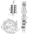
- FIG 3 the first embodiment of the invention is shown.
- the heat transfer plates (2) are provided with a smaller inlet channel (11) and reduced perimeter port (9) compared to that of conventional plates.
- the port (9) is sealed by a gasket (30) running around its perimeter in secondary sealing area (17) and enclosed in a gap (16) formed between the heat transfer plates (2) that constitute the first flow passage (13).
- the plates (2) do not abut around the port perimeter so that the interspace gap (16) around the port (9) and sealed by gasket (30) in-between the first flow passage (13) can be made semi rigid in nature so allowing the gasket (30) to be inserted into the gap (16) between the two plates even after the adjacent heat transfer plates (2) making up the first flow passage (13) have been permanently affixed to each other by welding in primary sealing area (24).
- successive first flow passages (13) each constituting a welded pair or cassette of plates are stacked one on top of another to produce the plate stack with each first flow passage (13) being sealed to the adjacent first flow passage (13) around the primary sealing area (24) by means of a gasket (19).
- the respective inlet passage (15) in this first embodiment can be formed by one or more holes (18) through one or both plates that constitute the first flow passage (13) in the area outside of the secondary sealing area (17) but inside the primary sealing area (24).
- the pressure drop producing means consists primarily of hole (18).
- the position, size and number of holes (18) can of course be varied to suit the heat transfer duty.
- This inlet passage (15) opens into a lateral distribution interspace (20) formed from a pressed form in one or both of the plates which constitute the first flow channel (13).
- the perimeter around this interspace (20) is in close abutment between both the plates (A and B) forming the first flow passage (13) except in the location of a pressed channel (21) that communicates on into the first flow passage (13).
- This pressed channel (21) forms a secondary pressure drop producing means which can be used to redirect flow laterally within the plane of the first flow passage (13).
- the flow entering the interspace (20) via the inlet passage (15) can be split into two or more streams of equal or unequal flow rates as desired to effect good lateral distribution within the first flow passage (13).
- Varying the size of channel (21) with respect to difference flow fingers (23) does little to influence the ratio of liquid to gas flow rates produced in lateral distribution but only the combined mixture feed rate in the direction of the distribution fingers (23).
- Liquid phase flow proceeds radially away from the point of impact along plate B and will largely continue until this radial liquid flow becomes parted by the entrance into two or more distribution fingers (23), formed by the perimeter of interspace (20) and surrounding the hole (18).
- the liquid phase entering through hole (18) can be redirected in any proportion desired and in any direction dictated by the flow fingers (23).
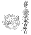
- the second embodiment of the invention is shown in which use is made of the secondary sealing gasket (30) to enclose and position a primary pressure drop producing means (31) in the form of a short length of small bore tubing which passes through the gasket to form the inlet passage (15).
- a primary pressure drop producing means (31) in the form of a short length of small bore tubing which passes through the gasket to form the inlet passage (15).
- the mixture flow rate, for any given pressure drop desired, through the inlet passage (15) into each first flow passage (13) from channel (11) can be altered by varying either the tube (31) diameter or tube length to suit the thermal duty.
- the proportion of liquid entering the distribution interspace (20) can be varied by changing the position of the entrance to the tube (31) within the inlet channel (11) with respect to the edge of the inlet port (9), i.e. dimension X can be varied.
- FIG 7 a section through the inlet port (9) is shown with the two phase mixture travelling from left to right into channel (11). If the two phase mixture were homogenous in nature, then the ratio between gas and liquid flow rates at any point in the channel (11) would be uniform and the flow rate through any pressure drop producing means would be dependant only on the geometry of said means and the pressure drop across the means.
- This second embodiment of the invention provides a means to accomplish this highly desired condition.
- the ratio of gas to liquid phase is equal to the inlet gas to liquid ratio as fed to pipe (6).
- This position x is dependant on the distance of any first flow passage (13) in the stack as measured from the inlet pipe (6) or the length down the inlet channel (11) from the cover plate (3). This position x corresponds to the dotted line shown in Figure 7.
- the entrance to tube (31) within the feed channel (11) must be positioned at this location and will change slightly for each successive first flow passage (13). Changes in length x for each first flow passage (13) may be made in a continuous manner from cover plate (3) to cover plate (4) as shown by the locus of position x (dotted line) or may be approximated in a step wise manner.
- the ability to easily adjust the pressure drop producing means by inserting a different gasket (30), tube (31) combination into any first flow passage (13) in the second embodiment of the invention means that an evaporator can be fine tuned for optimum distribution and thermal performance.
- the high velocity jet of two phase mixture emerges from the outlet of the tube (31) and enters the interspace (20) in a direction roughly parallel to the plane of the first flow passage (13) so does not impact plate B of the first flow passage (13) in a perpendicular manner.
- Liquid phase distribution in a lateral direction can not therefore be split into controlled proportions by virtue of the radial flow from a point of impact with plate B and instead use is made of a narrow gap expansion section (25) between the outlet of tube (31) and the entry into interspace (20).
- This expansion section (25) by virtue of its narrow gap “y” and expanding fan shape, spreads the jet emerging from the outlet of the tube (31) into a fan like shape, the velocity of the mixture being maintained by a narrowing plate to plate gap as the flow width is increasing prior to entry into the interspace (20). In this manner, a high shear rate is maintained and the liquid spread evenly across the entire flow width of expansion section (25).
- the entrance to the distribution fingers (23) formed by the perimeter of interspace (20) then parts this two phase flow into two or more directions. These distribution fingers (23) are used to direct the flow laterally into the first flow passage (13).
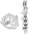
- the third embodiment of the invention shown in Figures 8 and 9 again makes use of the secondary sealing gasket (30) to enclose and position a pressure drop producing means (31) in the form of a short length of small bore tubing which passes through the gasket (30) to form the inlet passage (15).
- a pressure drop producing means (31) in the form of a short length of small bore tubing which passes through the gasket (30) to form the inlet passage (15).
- the outlet from the tube (31) does not directly enter an expansion section (25) but enters a redistribution or secondary inlet channel (26) formed by port (27).
- This secondary inlet channel (26) communicates with all first flow passages (13) in the stack but is prevented by a sealing gasket (33) from communication with the second flow passage.
- the sealing gasket (33) is fitted between each pair of plates that constitute a first flow passage (13).
- the secondary inlet channel (26) provides a redistribution stage to the process enabling any non-uniform feed rate that passes through any first pressure drop means (31) to be redistributed along channel (26) to one or more first flow passages (13) in the stack.
- the fourth embodiment of the invention shown in Figures 10 and 11 is identical to that of the third embodiment except that the sealing gasket (33) takes the form of a figure 8 and seals around both the inlet channel (11) and the secondary inlet channel (26) and is fitted with a secondary pressure drop producing means (35) such as a tube passing through the sealing means around the secondary inlet channel (26).
- the sealing gasket (33) takes the form of a figure 8 and seals around both the inlet channel (11) and the secondary inlet channel (26) and is fitted with a secondary pressure drop producing means (35) such as a tube passing through the sealing means around the secondary inlet channel (26).
- This tube provides communication to the interspace (34) which lies between the primary sealing gasket (19) and the secondary sealing gasket (33) above or below the interspace(20).
- This fourth embodiment thus combines the distribution benefits detailed in the first, second and third embodiments of the invention.
- the invention provides an arrangement in which a gasket is located in the gap between a pair of heat transfer plates and seals around the respective inlet ports of the plate pair.
- the arrangement is such that the gasket can be fitted in and removed from the gap even if the plates are bonded together to provide modular plate pairs.
- This has particular benefits when the pressure drop producing means is incorporated in the gasket itself, for example by a tube extending through the gasket, in allowing adjustments to be made by substituting different gasket/tube assemblies.
- the invention also consists in a plate heat exchanger formed by a stack of heat transfer plate pairs, sealing means between adjacent plate pairs to delimit first and second flow passages for first and second fluids, the first flow passages communicating with an inlet channel formed by through holes in the plates, and each plate pair having an internal gasket arranged between the plates around the through holes such that the gasket can be fitted and removed with the plate pair joined together.
Abstract
Description
Claims (16)
- A plate heat exchanger comprising a stack of heat transfer plates (2) which are provided with through inlet ports (9) forming an inlet channel (11) through the stack and, between the heat transfer plates (2), sealing means (19) which together with the heat transfer plates (2) in every other plate interspace delimit a first flow passage (13) for a first fluid and, in each of the remaining plate interspaces, delimit a second flow passage for a second fluid, wherein the inlet channel (11) communicates with each first flow passage (13) by way of at least one inlet passage (15) and is blocked from each second flow passage by sealing means (19) which is located in a primary sealing area (24) around each respective inlet port (9) characterised in that a gasket (30) is detachably located directly between a pair of permanently joined heat transfer plates (2) forming the first flow passage (13) and seals around the respective inlet ports (9) of the pair of permanently joined heat transfer plates (2), and the inlet passage (15) has pressure drop producing means formed by one or more holes (18) through one of the heat transfer plates (2) that define the first flow passage (13).
- A plate heat exchanger according to claim 1 characterised in that the hole(s) (18) open into an interspace (20) which is enclosed within the primary sealing area (24) and is formed by the two heat transfer plates (2) that make up the first flow passage (13).
- A plate heat exchanger according to claim 2 characterised in that the interspace (20) has a perimeter shape defined where the two heat transfer plates (2) touch or abut that produces, in the close proximity of the hole(s) (18), a junction between two or more distribution fingers (23) of which the other ends communicate into the first flow passage (13).
- A plate heat exchanger according to claim 3 characterised in that the distribution fingers (23) communicate into the first flow passage (13) through channels (21) that form a secondary pressure drop producing means.
- A plate heat exchanger comprising a stack of heat transfer plates (2) which are provided with through inlet ports (9) forming an inlet channel (11) through the stack and, between the heat transfer plates (2), sealing means (19) which together with the heat transfer plates (2) in every other plate interspace delimit a first flow passage (13) for a first fluid and, in each of the remaining plate interspaces, delimit a second flow passage for a second fluid, wherein the inlet channel (11) communicates with each first flow passage (13) by way of at least one inlet passage (15) and is blocked from each second flow passage by sealing means (19) which is located in a primary sealing area (24) around each respective inlet port (9) characterised in that a gasket (30) is detachably located directly between a pair of permanently joined heat transfer plates (2) forming the first flow passage (13) and seals around the respective inlet ports (9) of the pair of permanently joined heat transfer plates (2), and the inlet passage (15) has a pressure drop producing device (31) through the gasket (30).
- A plate heat exchanger according to claim 5 characterised in that the pressure drop producing device (31) comprises a narrow bore tube (31).
- A plate heat exchanger according to claim 6 characterised in that the overall length of the tube (31) can be varied with respect to the position of the first flow passage (13) within the overall stack of heat transfer plates (2).
- A plate heat exchanger according to claim 6 characterised in that the bore diameter of the tube (31) can be varied with respect to the position of the first flow passage (13) within the overall stack of heat transfer plates (2).
- A plate heat exchanger according to claim 6 characterised in that the position of an inlet end of the tube (31) extending into the inlet channel (11) can be varied with respect to the axis of the inlet channel (11) and is preferably varied with respect to the position of the first flow passage (13) within the stack of heat transfer plates (2).
- A plate heat exchanger according to claim 6 characterised in that an outlet end of the tube (31) communicates into an expansion section (25) which communicates with an interspace (20) which is enclosed within the primary sealing area (24) and is formed by the two plates (2) that make up the first flow passage (13), and the interspace (20) preferably has distribution fingers (23) which direct flow into the first flow passage (13).
- A plate heat exchanger according to claim 6 characterised in that an outlet end of the tube (31) communicates with a secondary inlet channel (26) formed by a secondary port (27) lying within the bounds enclosed by the primary sealing area (24) and the secondary inlet channel (26) provides communication into all first flow passages (13) within the stack.
- A plate heat exchanger according to claim 11 characterised in that the secondary inlet channel (26) communicates into an expansion section (25) which also communicates with an interspace (20) which is enclosed within the primary sealing area (24) and is formed by the two plates (2) that make up the first flow passage (13).
- A plate heat exchanger according to claim 11 or claim 12 characterised in that the secondary inlet channel (26) is prevented from communication with the second flow passage by a secondary sealing gasket (33) and the secondary sealing gasket has a secondary pressure drop producing device (35) to provide communication between the secondary inlet channel (26) and an interspace (34) within the stack.
- A plate heat exchanger according to claim 13 characterised in that the interspace (34) lies between the sealing means (19) and the secondary sealing gasket (33) and the interspace (34) communicates with the first flow passage (13) by means of one or more holes (18) in one or both plates (2) that constitute the first flow passage (13).
- A plate heat exchanger according to claim 10 or claim 12 characterised in that the expansion section (25) has a plate to plate gap (y), as measured within the first flow passage (13), much smaller than the mean plate to plate separation between the two plates (2) that delimit the first flow passage (13).
- A plate heat exchanger according to any one of the preceding claims characterised in that the gasket (30) is not fully enclosed by the heat transfer plates (2) in the direction leading back into the inlet channel (11).
Applications Claiming Priority (3)
| Application Number | Priority Date | Filing Date | Title |
|---|---|---|---|
| US368126 | 1982-04-14 | ||
| US09/368,126 US6478081B1 (en) | 1999-08-04 | 1999-08-04 | Plate heat exchanger |
| PCT/GB2000/002984 WO2001011301A1 (en) | 1999-08-04 | 2000-08-02 | Plate heat exchanger |
Publications (2)
| Publication Number | Publication Date |
|---|---|
| EP1203193A1 EP1203193A1 (en) | 2002-05-08 |
| EP1203193B1 true EP1203193B1 (en) | 2003-09-24 |
Family
ID=23449956
Family Applications (1)
| Application Number | Title | Priority Date | Filing Date |
|---|---|---|---|
| EP00949777A Expired - Lifetime EP1203193B1 (en) | 1999-08-04 | 2000-08-02 | Plate heat exchanger |
Country Status (8)
| Country | Link |
|---|---|
| US (1) | US6478081B1 (en) |
| EP (1) | EP1203193B1 (en) |
| JP (1) | JP4755793B2 (en) |
| AT (1) | ATE250745T1 (en) |
| AU (1) | AU6304800A (en) |
| DE (1) | DE60005529T2 (en) |
| DK (1) | DK1203193T3 (en) |
| WO (1) | WO2001011301A1 (en) |
Cited By (2)
| Publication number | Priority date | Publication date | Assignee | Title |
|---|---|---|---|---|
| WO2005066572A1 (en) * | 2004-01-09 | 2005-07-21 | Alfa Laval Corporate Ab | A plate heat exchanger |
| CN100447519C (en) * | 2005-06-30 | 2008-12-31 | 杭州钦宝制冷设备有限公司 | Plate type heat exchanger with multi-throttling device |
Families Citing this family (19)
| Publication number | Priority date | Publication date | Assignee | Title |
|---|---|---|---|---|
| SE516416C2 (en) * | 2000-05-19 | 2002-01-15 | Alfa Laval Ab | Plate package, heat transfer plate, plate heat exchanger and use of heat transfer plate |
| SE516537C2 (en) * | 2000-05-19 | 2002-01-29 | Alfa Laval Ab | Flat pack and plate heat exchanger |
| SE524783C2 (en) * | 2003-02-11 | 2004-10-05 | Alfa Laval Corp Ab | Plate package, plate heat exchanger and plate module |
| DE10317263B4 (en) * | 2003-04-14 | 2019-05-29 | Gea Wtt Gmbh | Plate heat exchanger with double-walled heat exchanger plates |
| DE10348803B4 (en) * | 2003-10-21 | 2024-03-14 | Modine Manufacturing Co. | Housing-less plate heat exchanger |
| SE531267C2 (en) * | 2004-10-21 | 2009-02-03 | Alfa Laval Corp Ab | Plate heat exchanger and plate module |
| SE528847C2 (en) * | 2005-01-28 | 2007-02-27 | Alfa Laval Corp Ab | Gasket assembly for plate heat exchanger |
| SE531241C2 (en) * | 2005-04-13 | 2009-01-27 | Alfa Laval Corp Ab | Plate heat exchanger with substantially uniform cylindrical inlet duct |
| KR100581843B1 (en) * | 2005-05-09 | 2006-05-22 | 대원열판(주) | Structure for combining heat plate with gasket of a plate type heat exchanger |
| SE530011C2 (en) * | 2006-06-05 | 2008-02-05 | Alfa Laval Corp Ab | Heat exchanger plate and plate heat exchanger |
| CN101589278B (en) * | 2006-10-13 | 2011-07-06 | 开利公司 | Multi-channel heat exchanger with multi-stage expansion device |
| SE533067C2 (en) * | 2008-10-03 | 2010-06-22 | Alfa Laval Corp Ab | plate heat exchangers |
| PT2267391T (en) * | 2009-06-26 | 2018-06-20 | Swep Int Ab | Asymmetric heat exchanger |
| EP2413045B1 (en) | 2010-07-30 | 2014-02-26 | Grundfos Management A/S | Heat exchange unit |
| EP2626661B1 (en) * | 2012-02-07 | 2018-02-28 | Danfoss A/S | stacked plate heat exchanger having a groove and a gasket |
| DK2639541T3 (en) * | 2012-03-14 | 2017-08-14 | Alfa Laval Corp Ab | HEAT TRANSMISSION PLATE |
| JP6970088B2 (en) | 2015-11-18 | 2021-11-24 | プロビビ インコーポレイテッド | Generation of aliphatic olefin derivatives via olefin metathesis |
| US10876794B2 (en) * | 2017-06-12 | 2020-12-29 | Ingersoll-Rand Industrial U.S., Inc. | Gasketed plate and shell heat exchanger |
| EP4303519A1 (en) | 2022-07-08 | 2024-01-10 | Stig Gregersen | A gas-liquid plate heat exchanger and method of assembling same |
Family Cites Families (12)
| Publication number | Priority date | Publication date | Assignee | Title |
|---|---|---|---|---|
| US2075236A (en) * | 1933-12-20 | 1937-03-30 | Aluminium Plant And Vessel Com | Heat exchange apparatus and element or plate therefor |
| US3735793A (en) * | 1971-05-04 | 1973-05-29 | Apv Co Ltd | Plate evaporators |
| DE2334798A1 (en) * | 1973-07-09 | 1975-01-30 | Ahlborn E Ag | LIQUID HEATERS |
| GB2084712B (en) * | 1980-09-29 | 1984-04-18 | Apv The Co Ltd | Improvements in/or relating to plate heat exchangers |
| JPS6226489A (en) * | 1985-07-24 | 1987-02-04 | Sakae Sangyo Kk | Panel type heat exchanger |
| SE464938B (en) * | 1989-11-02 | 1991-07-01 | Alfa Laval Desalt | PLATFORMERS WHEN THE SEALING ARRANGEMENT PROMOTES THE DISTRIBUTION OF THE VEETSKAN FOR THE PLATE SURFACE AND HEATER-EXHAUSTING STREAMS IN THE LOW PLATES |
| GB9119727D0 (en) * | 1991-09-16 | 1991-10-30 | Apv Baker Ltd | Plate heat exchanger |
| SE469669B (en) * | 1992-01-21 | 1993-08-16 | Alfa Laval Thermal Ab | DISTRIBUTION PATTERNS OF PLATFORM TRANSMITTERS |
| JPH05264193A (en) * | 1992-03-21 | 1993-10-12 | Hisaka Works Ltd | Plate type heat exchanger |
| SE502984C2 (en) | 1993-06-17 | 1996-03-04 | Alfa Laval Thermal Ab | Flat heat exchanger with specially designed door sections |
| US5435383A (en) * | 1994-02-01 | 1995-07-25 | Rajagopal; Ramesh | Plate heat exchanger assembly |
| IT1276990B1 (en) | 1995-10-24 | 1997-11-03 | Tetra Laval Holdings & Finance | PLATE HEAT EXCHANGER |
-
1999
- 1999-08-04 US US09/368,126 patent/US6478081B1/en not_active Expired - Lifetime
-
2000
- 2000-08-02 AU AU63048/00A patent/AU6304800A/en not_active Abandoned
- 2000-08-02 JP JP2001515912A patent/JP4755793B2/en not_active Expired - Fee Related
- 2000-08-02 DK DK00949777T patent/DK1203193T3/en active
- 2000-08-02 WO PCT/GB2000/002984 patent/WO2001011301A1/en active IP Right Grant
- 2000-08-02 AT AT00949777T patent/ATE250745T1/en not_active IP Right Cessation
- 2000-08-02 DE DE60005529T patent/DE60005529T2/en not_active Expired - Lifetime
- 2000-08-02 EP EP00949777A patent/EP1203193B1/en not_active Expired - Lifetime
Cited By (2)
| Publication number | Priority date | Publication date | Assignee | Title |
|---|---|---|---|---|
| WO2005066572A1 (en) * | 2004-01-09 | 2005-07-21 | Alfa Laval Corporate Ab | A plate heat exchanger |
| CN100447519C (en) * | 2005-06-30 | 2008-12-31 | 杭州钦宝制冷设备有限公司 | Plate type heat exchanger with multi-throttling device |
Also Published As
| Publication number | Publication date |
|---|---|
| DE60005529T2 (en) | 2004-04-29 |
| EP1203193A1 (en) | 2002-05-08 |
| JP2003506663A (en) | 2003-02-18 |
| JP4755793B2 (en) | 2011-08-24 |
| DE60005529D1 (en) | 2003-10-30 |
| WO2001011301A1 (en) | 2001-02-15 |
| ATE250745T1 (en) | 2003-10-15 |
| DK1203193T3 (en) | 2004-02-02 |
| AU6304800A (en) | 2001-03-05 |
| US6478081B1 (en) | 2002-11-12 |
Similar Documents
| Publication | Publication Date | Title |
|---|---|---|
| EP1203193B1 (en) | Plate heat exchanger | |
| KR101292362B1 (en) | Plate Heat Exchanger | |
| US5924484A (en) | Plate heat exchanger | |
| ITMI952192A1 (en) | PLATE HEAT EXCHANGER | |
| US6948559B2 (en) | Three-fluid evaporative heat exchanger | |
| EP2929273B1 (en) | Plate heat exchanger | |
| EP2219004B1 (en) | Multi-chamber heat exchanger header and method of making | |
| JP2007518053A (en) | Heat exchanger and its heat exchange module | |
| EP1022533B1 (en) | Heat exchanger | |
| WO2006043864A1 (en) | A plate heat exchanger and a plate module | |
| EP1702193A1 (en) | A plate heat exchanger | |
| JP2004340569A (en) | Plate-heat exchanger | |
| JPS6039960B2 (en) | Shell and plate heat exchanger | |
| JP3219380B2 (en) | Plate heat exchanger | |
| WO2001031278A1 (en) | Heat exchanger | |
| JP3500212B2 (en) | Stacked heat exchanger | |
| KR20020071899A (en) | Plate Heat Exchanger | |
| GB2418481A (en) | Plate heat exchanger having a corrugated portion joined to a separate header portion | |
| KR20000051820A (en) | Plate-Fin type heat exchanger |
Legal Events
| Date | Code | Title | Description |
|---|---|---|---|
| PUAI | Public reference made under article 153(3) epc to a published international application that has entered the european phase |
Free format text: ORIGINAL CODE: 0009012 |
|
| 17P | Request for examination filed |
Effective date: 20020226 |
|
| AK | Designated contracting states |
Kind code of ref document: A1 Designated state(s): AT BE CH CY DE DK ES FI FR GB GR IE IT LI LU MC NL PT SE |
|
| AX | Request for extension of the european patent |
Free format text: AL;LT;LV;MK;RO;SI |
|
| 17Q | First examination report despatched |
Effective date: 20020819 |
|
| GRAH | Despatch of communication of intention to grant a patent |
Free format text: ORIGINAL CODE: EPIDOS IGRA |
|
| GRAS | Grant fee paid |
Free format text: ORIGINAL CODE: EPIDOSNIGR3 |
|
| GRAA | (expected) grant |
Free format text: ORIGINAL CODE: 0009210 |
|
| AK | Designated contracting states |
Kind code of ref document: B1 Designated state(s): AT BE CH CY DE DK ES FI FR GB GR IE IT LI LU MC NL PT SE |
|
| PG25 | Lapsed in a contracting state [announced via postgrant information from national office to epo] |
Ref country code: LI Free format text: LAPSE BECAUSE OF FAILURE TO SUBMIT A TRANSLATION OF THE DESCRIPTION OR TO PAY THE FEE WITHIN THE PRESCRIBED TIME-LIMIT Effective date: 20030924 Ref country code: CH Free format text: LAPSE BECAUSE OF FAILURE TO SUBMIT A TRANSLATION OF THE DESCRIPTION OR TO PAY THE FEE WITHIN THE PRESCRIBED TIME-LIMIT Effective date: 20030924 Ref country code: FI Free format text: LAPSE BECAUSE OF FAILURE TO SUBMIT A TRANSLATION OF THE DESCRIPTION OR TO PAY THE FEE WITHIN THE PRESCRIBED TIME-LIMIT Effective date: 20030924 Ref country code: AT Free format text: LAPSE BECAUSE OF FAILURE TO SUBMIT A TRANSLATION OF THE DESCRIPTION OR TO PAY THE FEE WITHIN THE PRESCRIBED TIME-LIMIT Effective date: 20030924 Ref country code: FR Free format text: LAPSE BECAUSE OF FAILURE TO SUBMIT A TRANSLATION OF THE DESCRIPTION OR TO PAY THE FEE WITHIN THE PRESCRIBED TIME-LIMIT Effective date: 20030924 Ref country code: NL Free format text: LAPSE BECAUSE OF FAILURE TO SUBMIT A TRANSLATION OF THE DESCRIPTION OR TO PAY THE FEE WITHIN THE PRESCRIBED TIME-LIMIT Effective date: 20030924 Ref country code: CY Free format text: LAPSE BECAUSE OF FAILURE TO SUBMIT A TRANSLATION OF THE DESCRIPTION OR TO PAY THE FEE WITHIN THE PRESCRIBED TIME-LIMIT Effective date: 20030924 Ref country code: BE Free format text: LAPSE BECAUSE OF FAILURE TO SUBMIT A TRANSLATION OF THE DESCRIPTION OR TO PAY THE FEE WITHIN THE PRESCRIBED TIME-LIMIT Effective date: 20030924 Ref country code: IT Free format text: LAPSE BECAUSE OF FAILURE TO SUBMIT A TRANSLATION OF THE DESCRIPTION OR TO PAY THE FEE WITHIN THE PRE;WARNING: LAPSES OF ITALIAN PATENTS WITH EFFECTIVE DATE BEFORE 2007 MAY HAVE OCCURRED AT ANY TIME BEFORE 2007. THE CORRECT EFFECTIVE DATE MAY BE DIFFERENT FROM THE ONE RECORDED.SCRIBED TIME-LIMIT Effective date: 20030924 |
|
| REG | Reference to a national code |
Ref country code: GB Ref legal event code: FG4D |
|
| REG | Reference to a national code |
Ref country code: SE Ref legal event code: TRGR Ref country code: CH Ref legal event code: EP |
|
| REG | Reference to a national code |
Ref country code: IE Ref legal event code: FG4D |
|
| REF | Corresponds to: |
Ref document number: 60005529 Country of ref document: DE Date of ref document: 20031030 Kind code of ref document: P |
|
| PG25 | Lapsed in a contracting state [announced via postgrant information from national office to epo] |
Ref country code: GR Free format text: LAPSE BECAUSE OF FAILURE TO SUBMIT A TRANSLATION OF THE DESCRIPTION OR TO PAY THE FEE WITHIN THE PRESCRIBED TIME-LIMIT Effective date: 20031224 |
|
| PG25 | Lapsed in a contracting state [announced via postgrant information from national office to epo] |
Ref country code: ES Free format text: LAPSE BECAUSE OF FAILURE TO SUBMIT A TRANSLATION OF THE DESCRIPTION OR TO PAY THE FEE WITHIN THE PRESCRIBED TIME-LIMIT Effective date: 20040104 |
|
| REG | Reference to a national code |
Ref country code: DK Ref legal event code: T3 |
|
| NLV1 | Nl: lapsed or annulled due to failure to fulfill the requirements of art. 29p and 29m of the patents act | ||
| LTIE | Lt: invalidation of european patent or patent extension |
Effective date: 20030924 |
|
| REG | Reference to a national code |
Ref country code: CH Ref legal event code: PL |
|
| PLBE | No opposition filed within time limit |
Free format text: ORIGINAL CODE: 0009261 |
|
| STAA | Information on the status of an ep patent application or granted ep patent |
Free format text: STATUS: NO OPPOSITION FILED WITHIN TIME LIMIT |
|
| PG25 | Lapsed in a contracting state [announced via postgrant information from national office to epo] |
Ref country code: LU Free format text: LAPSE BECAUSE OF NON-PAYMENT OF DUE FEES Effective date: 20040802 Ref country code: GB Free format text: LAPSE BECAUSE OF NON-PAYMENT OF DUE FEES Effective date: 20040802 Ref country code: IE Free format text: LAPSE BECAUSE OF NON-PAYMENT OF DUE FEES Effective date: 20040802 |
|
| PG25 | Lapsed in a contracting state [announced via postgrant information from national office to epo] |
Ref country code: MC Free format text: LAPSE BECAUSE OF NON-PAYMENT OF DUE FEES Effective date: 20040831 |
|
| 26N | No opposition filed |
Effective date: 20040625 |
|
| EN | Fr: translation not filed | ||
| GBPC | Gb: european patent ceased through non-payment of renewal fee |
Effective date: 20040802 |
|
| REG | Reference to a national code |
Ref country code: IE Ref legal event code: MM4A |
|
| PG25 | Lapsed in a contracting state [announced via postgrant information from national office to epo] |
Ref country code: PT Free format text: LAPSE BECAUSE OF NON-PAYMENT OF DUE FEES Effective date: 20040224 |
|
| PGFP | Annual fee paid to national office [announced via postgrant information from national office to epo] |
Ref country code: DE Payment date: 20140827 Year of fee payment: 15 |
|
| PGFP | Annual fee paid to national office [announced via postgrant information from national office to epo] |
Ref country code: SE Payment date: 20140827 Year of fee payment: 15 |
|
| PGFP | Annual fee paid to national office [announced via postgrant information from national office to epo] |
Ref country code: DK Payment date: 20150825 Year of fee payment: 16 |
|
| REG | Reference to a national code |
Ref country code: DE Ref legal event code: R119 Ref document number: 60005529 Country of ref document: DE |
|
| REG | Reference to a national code |
Ref country code: SE Ref legal event code: EUG |
|
| REG | Reference to a national code |
Ref country code: DE Ref legal event code: R082 Ref document number: 60005529 Country of ref document: DE Representative=s name: WEICKMANN & WEICKMANN PATENTANWAELTE - RECHTSA, DE Ref country code: DE Ref legal event code: R082 Ref document number: 60005529 Country of ref document: DE Representative=s name: WEICKMANN & WEICKMANN PATENT- UND RECHTSANWAEL, DE |
|
| PG25 | Lapsed in a contracting state [announced via postgrant information from national office to epo] |
Ref country code: SE Free format text: LAPSE BECAUSE OF NON-PAYMENT OF DUE FEES Effective date: 20150803 |
|
| PG25 | Lapsed in a contracting state [announced via postgrant information from national office to epo] |
Ref country code: DE Free format text: LAPSE BECAUSE OF NON-PAYMENT OF DUE FEES Effective date: 20160301 |
|
| REG | Reference to a national code |
Ref country code: DK Ref legal event code: EBP Effective date: 20160831 |
|
| PG25 | Lapsed in a contracting state [announced via postgrant information from national office to epo] |
Ref country code: DK Free format text: LAPSE BECAUSE OF NON-PAYMENT OF DUE FEES Effective date: 20160831 |