EP1202766B1 - Seringue sans aiguille avec injecteur a elements emboites - Google Patents
Seringue sans aiguille avec injecteur a elements emboites Download PDFInfo
- Publication number
- EP1202766B1 EP1202766B1 EP00949593A EP00949593A EP1202766B1 EP 1202766 B1 EP1202766 B1 EP 1202766B1 EP 00949593 A EP00949593 A EP 00949593A EP 00949593 A EP00949593 A EP 00949593A EP 1202766 B1 EP1202766 B1 EP 1202766B1
- Authority
- EP
- European Patent Office
- Prior art keywords
- injector
- groove
- elements
- needleless syringe
- syringe according
- Prior art date
- Legal status (The legal status is an assumption and is not a legal conclusion. Google has not performed a legal analysis and makes no representation as to the accuracy of the status listed.)
- Expired - Lifetime
Links
Images


Classifications
-
- A—HUMAN NECESSITIES
- A61—MEDICAL OR VETERINARY SCIENCE; HYGIENE
- A61M—DEVICES FOR INTRODUCING MEDIA INTO, OR ONTO, THE BODY; DEVICES FOR TRANSDUCING BODY MEDIA OR FOR TAKING MEDIA FROM THE BODY; DEVICES FOR PRODUCING OR ENDING SLEEP OR STUPOR
- A61M5/00—Devices for bringing media into the body in a subcutaneous, intra-vascular or intramuscular way; Accessories therefor, e.g. filling or cleaning devices, arm rests
- A61M5/178—Syringes
- A61M5/30—Syringes for injection by jet action, without needle, e.g. for use with replaceable ampoules or carpules
-
- A—HUMAN NECESSITIES
- A61—MEDICAL OR VETERINARY SCIENCE; HYGIENE
- A61M—DEVICES FOR INTRODUCING MEDIA INTO, OR ONTO, THE BODY; DEVICES FOR TRANSDUCING BODY MEDIA OR FOR TAKING MEDIA FROM THE BODY; DEVICES FOR PRODUCING OR ENDING SLEEP OR STUPOR
- A61M5/00—Devices for bringing media into the body in a subcutaneous, intra-vascular or intramuscular way; Accessories therefor, e.g. filling or cleaning devices, arm rests
- A61M5/178—Syringes
- A61M5/30—Syringes for injection by jet action, without needle, e.g. for use with replaceable ampoules or carpules
- A61M5/3007—Syringes for injection by jet action, without needle, e.g. for use with replaceable ampoules or carpules with specially designed jet passages at the injector's distal end
-
- A—HUMAN NECESSITIES
- A61—MEDICAL OR VETERINARY SCIENCE; HYGIENE
- A61M—DEVICES FOR INTRODUCING MEDIA INTO, OR ONTO, THE BODY; DEVICES FOR TRANSDUCING BODY MEDIA OR FOR TAKING MEDIA FROM THE BODY; DEVICES FOR PRODUCING OR ENDING SLEEP OR STUPOR
- A61M5/00—Devices for bringing media into the body in a subcutaneous, intra-vascular or intramuscular way; Accessories therefor, e.g. filling or cleaning devices, arm rests
- A61M5/178—Syringes
- A61M5/31—Details
- A61M5/3129—Syringe barrels
- A61M5/3134—Syringe barrels characterised by constructional features of the distal end, i.e. end closest to the tip of the needle cannula
Definitions
- the present invention is in the field of needleless syringes used for injections Intradermal, subcutaneous and intramuscular liquid active ingredient for therapeutic use in medicine human or veterinary.
- US Patent 3,802,430 describes a syringe without needle in which the liquid to be injected is repressed by a piston repelled by gases produced by a pyrotechnic generator; this syringe has five parallel to the axis of the syringe and circular cross sections.
- the patent US 3,788,315 discloses a syringe in which the plunger liquid is pushed back by the relaxation of compressed gas or spring. This syringe comprises six ducts of circular cross sections and whose axes are slightly divergent from the axis of the syringe.
- the injector placed at the downstream part of the syringe, must not deform under the effect of the liquid pressure during injection: the injector must be relatively thick, and all the more so as the ducts are spread over a large area. The problem is going to be to conduct ducts in general very fine on large thicknesses.
- the performance of the injector lies in the possibility of controlling the distance of coherence jets exiting ducts or nozzles, for conditions predetermined use (nature of the liquid, pressure injection), by cross-section ducts appropriate.
- This relevant cross section has aim to create a field of turbulence in flow such that, at a short distance from the outlet of the injector, the jet remains coherent, that is to say that it is thin and fast enough to pierce and penetrate the skin of the subject to be treated, then the jet loses very quickly of its coherence: it explodes to diffuse better the active ingredient under the skin.
- the problem is simply realize, not just fine ducts on large thicknesses but especially ducts with appropriate cross sections.
- the present invention relates to a syringe without needle for intradermal, subcutaneous or intramuscular injection of a liquid active ingredient initially placed between, on the one hand an injector comprising at least an injection nozzle, said injector being placed at skin contact, where at a very short distance from the skin the subject to be treated and secondly a movable wall, under the effect of a propulsive system, ensuring the implementation pressure and expulsion of the active ingredient through the injector placed at the downstream end of the syringe, which is such that the injector is constituted by at least two elements whose surfaces in contact are directed to the skin, at least one of the surfaces in contact having at least one groove which constitutes a nozzle injection in the assembly of said elements.
- liquid active principle we will basically hear a more or less liquid viscous, or a mixture of liquids, or a gel.
- the active ingredient can be a solid solution in a solvent suitable for injection.
- the principle active may be a solid in powder form put in suspension, more or less concentrated, in a liquid appropriate.
- the granulometry of the solid active ingredient must be adapted as well as the shape of the conduit for avoid clogging of the ducts.
- a constituent element of the injector comprises a face being on the side of the active ingredient: it will be said upstream face, a face located on the side of the skin: it will be called downstream face and a lateral surface of which all or part is in contact with all or part of the lateral surface of at least one other element.
- a groove can be opposite the lateral surface an adjacent element; she can also be screwed to screw of another groove drawn on the lateral face of the other adjacent element; the grooves placed in screws to screws may have identical cross-sections or different.
- the contact surfaces of two elements adjacent, contact surfaces that are all or part lateral surfaces of said elements, are surfaces of revolution.
- the contact surfaces of two adjacent elements, surfaces of contact that are all or parts of the surfaces side of said elements, are flat surfaces.
- the transverse dimensions of a groove are very small vis-à-vis the length of the groove. We can be said as a first approximation that the groove positions around a curve drawn on a portion of lateral surface of a constituent element of the injector.
- this curve drawn on the lateral face is substantially rectilinear: the groove will be said rectilinear. This is for example the case of a longitudinal groove made on a surface she even flat, or cylindrical or conical.
- this curve drawn on the lateral face is not rectilinear or is a left curve contained in any plane, the groove will be called helical. This is for example the case of a groove helical made on a cylindrical surface or conical.
- this groove is formed by the convergence of at least two portions of grooves starting from the upstream side of the element and ending with a single groove portion to the downstream face of the element.
- the different portions of grooves are rectilinear or helical.
- the groove has a section cross-section substantially constant when groove from the upstream face to the downstream face of the element.
- Her cross-section is, preferably of shape simple geometric, this is for example a throat-shaped "V", "U”, or semicircle. These forms present a plane of symmetry that passes through an axis of symmetry of the element.
- the groove has a section transversal evolutionary.
- its section transverse varies or evolves by increasing or decreasing, in a regular or abrupt way, so that the nozzle has a succession of tubular parts and cavities, the proper arrangement of these different parts to control and control the consistency distance of the jet according to the conditions predetermined use: viscosity of the liquid to inject, injection pressure in particular.
- Such an evolutionary cross section is by example made simply from a groove of constant cross section, like the one previously described, on which at least one footprint that broadens and deepens locally the groove.
- the so-called footprints will create cavities along the injection nozzle that will be cross-section evolutionary, this provision making it possible to control the distance of coherence of the jet.
- the groove can be a succession footprints very close to each other constitute the progressive cross section groove.
- the injector comprises a support comprising less a dwelling in which is fitted an element that constitutes a monoblock core. Said core and support having grooves for making at least one nozzle injection.
- the injector comprises at least one core consisting of at least two elements or neighborhoods assembled by their flat faces to achieve at least a nozzle with an evolutive cross-section, the elements or neighborhoods of the different nuclei being nested in housing a support.
- the nesting is preferably a press fitting which ensures also the sealing at the contact surfaces.
- the one-piece or multi-core neighborhoods presents either a symmetry of revolution; the core has the shape of a cylinder or a truncated cone a n-order repetition symmetry: the kernel has the shape of a prism or pyramid trunk. Obviously the housing that receives the core has the same form, it has a conjugate form to make nesting.
- the injector comprises at least one core made up of at least two neighborhoods assembled by their flat faces to achieve at least one nozzle to evolutionary cross-section, the neighborhoods of different cores being secured by overmolding.
- Nest assemblies in which a sub set comprising a support or overmolding equipped with their cores are also part of the invention.
- the preferred nesting assembly is the one formed by the nesting of a core in a support comprising a only housing, this nesting serving as a nucleus for a other support to a single dwelling.
- a realization particularly simple is to nest a nucleus directly into the downstream end of the syringe arranged for this purpose.
- the assembly and the assembly will be done so that the downstream face is the one of smaller section: by this assembly the pressure of the liquid will tend to fit the elements and not to drive them out of their homes.
- the present invention also relates to an injector such injector is constituted by at least two elements whose contact surfaces are directed towards the skin, at least one of the contacting surfaces comprising at least one groove which constitutes an injection nozzle in the assembly of said elements.
- a syringe according to the invention solves the problems posed.
- the increase thickness does not present any difficulty with regard to the realization of fine ducts with sections transversal evolutionary or not on. some big thicknesses.
- the invention can be done in a simple way, to adapt to predetermined conditions of use, the control of the coherence distance of the jets leaving the nozzles.
- the injector comprises elements of simple shapes and easy to achieve, by direct molding of the elements of the injector or by machining grooves and impressions on blanks manufactured elsewhere. All of these operations fabrications and assembly lends itself to a advanced automation.
- the syringe according to the invention also has a undeniable advantage from the point of view of safety in case of abnormal use. For example if the syringe is directed to a face and triggered accidentally, the jets will have no other effects than to water said face of active ingredient, without any mechanical piercing effect, if the syringe is not in contact (or very close) with the face. This advantage is related to the control of the coherence distance of the jet.
- Figure 1 represents, in longitudinal section partial, a syringe according to the invention.
- FIG. 2 represents, in cross-section, the injector of said syringe.
- Figures 3 and 4 show, in perspective, types of cores usable in the injector of the syringe previously shown.
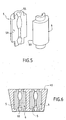
- FIG. 5 shows, in perspective, two elements of a core according to another embodiment of the invention.
- FIG. 6 represents, in longitudinal section, a syringe injector obtained by assembling elements of the type shown in Figure 5.
- FIG. 1 schematically shows a syringe without needle for injection of active principle liquid.
- a syringe is generally cylindrical and comprises a reservoir containing the active ingredient 7.
- This tank is closed at one end, which we have called downstream end 2, by an injector 1 comprising at least one conduit or an injection nozzle.
- This injector is usually supported on the skin of the subject to treat, or maintain at a very short distance, the skin is not shown in this drawing.
- This injector is the end of the tank, or is an insert 3, fixed on this end of the tank by means appropriate.
- the other end of the tank is closed by a displaceable wall, for example a piston 8 including means for sealing such than an O-ring.
- the syringe has a propulsion system 9 with a triggering device to move the piston and inject the liquid.
- a propulsion system 9 with a triggering device to move the piston and inject the liquid.
- a pyrotechnic generator of gas as described in US Patent 3,802,430 previously cited
- gas expansion or a compressed spring as described in the patent US 3 788 315. It is evident that the syringes according to the invention can be equipped with any of these types of propulsion system to move the piston.
- Injector 1 (see also Fig. 2) is fitted to force in the end 2 of the syringe.
- This injector has a substantially cylindrical support 4 with an outer lateral face 40 resting on the face inner side 20 of the tip of the syringe and an inner side face 40 'on which comes in contact the outer lateral face 30 of a core 3, monoblock in this example.
- the support 4 and the core 3 each have, on the upstream side, a shoulder which serves blocking and stalling of these elements 3 and 4 in assembly; this shoulder is in this example truncated. Grooves on the side walls exterior extend into the frustoconical shoulder.
- Figure 2 shows in cross section the downstream end 2 of the syringe previously described.
- the support 4 is fitted in the end 2 of the syringe, the contact faces being respectively the lateral faces 40 and 20 '.
- the support 4 is nested a core 3, the contact faces being respectively the lateral faces 40 'and 30.
- the lateral face 40 of the support 4 has four grooves, such as the groove 41, they are equidistributed and have substantially the shape of a semicircle, say grooves are opposite the lateral surface 20 of the downstream end 2 of the syringe.
- the side face 40 'of the support 4 also has four grooves, such as groove 41 ', similar to previous, also equidistributed, but shifted by 45 ° relative to the outer grooves.
- the face 30 of the core 3 has eight grooves, such than the groove 31, they are equidistributed and have a cross section in the shape of "V". Among these grooves, one out of two, is opposite a groove such as groove 41 ', the other grooves are opposite the inner side wall 40 'of the support.
- grooves on external side walls such as grooves 31 or 41, extend in the frustoconical shoulder of the core 3 and the support 4.
- the transverse dimensions of the grooves are as they correspond to circular orifices of equivalent diameter 0.05mm to 0.5mm.
- the height of a element of the injector is between about 3mm and about 10mm.
- the orifices of the grooves are distributed on concentric circles whose diameters are between 3mm and 30mm.
- Figure 3 shows a perspective view of a core 33. This core is mounted on a support of the type shown in the previous figures.
- the core 33 is essentially cylindrical circular, it has on the upstream side a shoulder frustoconical of which we see the upstream face 331.
- the surface side of the core has eight grooves 53 equidistributed, they are longitudinal and section semicircular; these grooves extend into the shoulder.
- On each groove are two footprints 63 cone-shaped that widen and deepen the groove locally.
- the kernel has, on the part circular, a diameter of 8mm and its total height (with shoulder) is 5.8mm; the grooves are from semi-cylindrical shape with a radius of 0.1mm, cones have an apex angle of 90 ° and a base circular 1mm diameter.
- Figure 4 shows in perspective another core 34.
- This nucleus is the combination of a frustoconical part upstream and a cylindrical part downstream, this combination of form realizes the self-locking of the core in its housing.
- the lateral surface 340 of the core comprises 8 groups of equidistributed grooves.
- the cross section of the grooves in the shape of a "U”.
- On the frustoconical portion of the lateral surface 340, from the upstream face 341 two portions of identical grooves converge to gather in a single groove, of the same cross section on the cylindrical portion of the lateral surface to open on the downstream face.
- the shear at the confluence of two flows will generate turbulence to control the coherence distance of the jet.
- Figure 5 shows in perspective a core consisting of several parts or example two parts 5 and 6 basically having the form of two half-cylinders clearly represented separated for the readability of the schema. These two half-cylinders 5 and 6 will be joined by their flat faces 50 and 60 (the latter is hidden for element 6). In this example, each flat face has in its middle, an evolutionary cross-section groove. Given its slightly different appearance from what has been previously described we will call it also footprint, but said footprint is a groove in evolutionary cross section according to the invention.
- FIG. 6 represents, in cross-section a injector 10 consisting of two cores comprising two parts 5,6 assembled in an overmolding 45; rooms 5.6, have at both ends a portion of diameter reduced who realize shoulders for centering elements in the overmolding.
- a conduit 55 with symmetry of revolution and evolutionary cross section comprising, in this example, from the upstream face to the downstream face, a truncated cone connecting to an oblong cavity, then a circular cylindrical portion connecting to a cavity formed of two unequal conical truncated cones by their broadest bases.
- the thickness of an element of the injector distance from the upstream face to the downstream face, is between about 3mm and about 10mm.
- the dimensions of the cross sections of the grooves or footprints evolve and are such that the area corresponds to that of a circular duct of diameter varies between approximately 50 ⁇ m and 1000 ⁇ m.
- the materials for making the syringe and the different parts of the nozzle will be chosen from compatible and approved materials for medical use; without pretending to be exhaustive we will quote for example plastic materials such as polycarbonate, polytetrafluoroethylenes; metals; stainless steel, or glass for medical use of type I or II.
Landscapes
- Health & Medical Sciences (AREA)
- Vascular Medicine (AREA)
- Engineering & Computer Science (AREA)
- Anesthesiology (AREA)
- Biomedical Technology (AREA)
- Heart & Thoracic Surgery (AREA)
- Hematology (AREA)
- Life Sciences & Earth Sciences (AREA)
- Animal Behavior & Ethology (AREA)
- General Health & Medical Sciences (AREA)
- Public Health (AREA)
- Veterinary Medicine (AREA)
- Infusion, Injection, And Reservoir Apparatuses (AREA)
Description
Ce noyau, à géométrie de révolution, est la combinaison d'une partie tronconique à l'amont et d'une partie cylindrique à l'aval, cette combinaison de forme réalise l'autoblocage du noyau dans son logement. La surface latérale 340 du noyau comporte 8 groupes de rainures équiréparties. La section transversale des rainures à la forme d'un « U ». Sur la partie tronconique de la surface latérale 340, depuis la face amont 341 deux portions de rainures identiques convergent pour se rassembler en une seule rainure, de même section transversale sur la partie cylindrique de la surface latérale pour déboucher sur la face aval. Dans cet exemple le cisaillement à la confluence de deux écoulements va générer la turbulence pour contrôler la distance de cohérence du jet.
Claims (12)
- Seringue sans aiguille pour l'injection d'un principe actif (7) initialement placé entre, d'une part un injecteur (1,10) comportant au moins une buse d'injection, ledit injecteur étant placé à l'extrémité aval (2) de la seringue, et d'autre part une paroi déplaçable (8) sous l'effet d'un système propulsif (9) assurant la mise en pression et l'expulsion du principe actif au travers de l'injecteur, caractérisée en ce que, l'injecteur (1,10) est constitué par l'assemblage d'au moins deux éléments (3,4,5,6,33,34) ; chaque élément ayant une face aval, une face amont et une surface latérale les reliant, les surfaces en contact (30, 40, 40', 50, 60, 330, 340) desdits éléments dans l'assemblage étant tout ou partie des surfaces latérales desdits éléments ; au moins une des surfaces en contact comportant au moins une rainure (31,41,41',53,54,55) qui constitue une buse d'injection dans l'assemblage des dits éléments.
- Seringue sans aiguille selon la revendication 1 caractérisée en ce que les surfaces en contact (30,40,40') sont des surfaces de révolution.
- Seringue sans aiguille selon la revendication 1 caractérisée en ce que les surfaces de contact (50,60) sont des surfaces planes.
- Seringue sans aiguille selon l'une des revendications 1,2 ou 3 caractérisée en ce que la rainure (31,41,41') est rectiligne.
- Seringue sans aiguille selon l'une des revendications 1 ou 2 caractérisée en ce que la rainure est hélicoïdale.
- Seringue sans aiguille selon l'une des revendications 1,2 ou 3 caractérisée en ce qu'une rainure (54) est formée par la convergence d'au moins deux rainures, débutant à partir de la face amont, se terminant par une seule rainure vers la face aval de l'élément (34).
- Seringue selon l'une des revendications 4,5 ou 6 caractérisée en ce que la rainure (31,41,41')a une section transversale constante.
- Seringue selon l'une des revendications 4,5 ou 6 caractérisée en ce que la rainure (53,54,55) a une section transversale évolutive.
- Seringue sans aiguille selon l'une des revendications 1,2,3 ou 8 caractérisée en ce que l'injecteur (1) comprend un support (4) comportant un logement dans lequel est emboíté un noyau monobloc (3,33,34).
- Seringue sans aiguille selon l'une des revendications 1,3 ou 8 caractérisée en ce que l'injecteur, comprend au moins un noyau constitué d'au moins deux quartiers assemblés par leurs faces planes pour réaliser au moins un noyau avec une buse de section transversale évolutive, les quartiers des différents noyaux étant emboítés dans des logements d'un support.
- Seringue sans aiguille selon l'une des revendications 1,2,3 ou 8 caractérisée en ce que l'injecteur (10) comprend au moins un noyau constitué d'au moins deux quartiers (5,6,) assemblés par leurs faces planes (50,60) pour réaliser au moins un noyau avec une buse (55) à section transversale évolutive, les quartiers (5,6,) des différents noyaux étant solidarisés par un surmoulage (45).
- Injecteur (1,10), pour seringue sans aiguille, caractérisé en ce que le dit injecteur est constitué par au moins deux éléments (3,4,5,6,30,33,34) ; chaque élément ayant une face aval parallèle à la face aval de l'injecteur, une face amont et une surface latérale les reliant, les surfaces en contact (30, 40, 40', 50, 60, 330, 340) desdits éléments dans l'assemblage étant tout ou partie des surfaces latérales desdits éléments ; au moins une des surfaces en contact comportant au moins une rainure (31,41,41',53,54,55) qui constitue une buse d'injection dans l'assemblage des dits éléments.
Applications Claiming Priority (3)
| Application Number | Priority Date | Filing Date | Title |
|---|---|---|---|
| FR9909252 | 1999-07-16 | ||
| FR9909252A FR2796288B1 (fr) | 1999-07-16 | 1999-07-16 | Seringue sans aiguille avec injecteur a elements emboites |
| PCT/FR2000/001851 WO2001005454A1 (fr) | 1999-07-16 | 2000-06-30 | Seringue sans aiguille avec injecteur a elements emboites |
Publications (2)
| Publication Number | Publication Date |
|---|---|
| EP1202766A1 EP1202766A1 (fr) | 2002-05-08 |
| EP1202766B1 true EP1202766B1 (fr) | 2004-09-15 |
Family
ID=9548184
Family Applications (1)
| Application Number | Title | Priority Date | Filing Date |
|---|---|---|---|
| EP00949593A Expired - Lifetime EP1202766B1 (fr) | 1999-07-16 | 2000-06-30 | Seringue sans aiguille avec injecteur a elements emboites |
Country Status (17)
| Country | Link |
|---|---|
| US (1) | US6981961B1 (fr) |
| EP (1) | EP1202766B1 (fr) |
| JP (2) | JP2003504162A (fr) |
| CN (1) | CN1195557C (fr) |
| AT (1) | ATE275994T1 (fr) |
| AU (1) | AU760877B2 (fr) |
| BR (1) | BR0012509B1 (fr) |
| CA (1) | CA2379246C (fr) |
| DE (1) | DE60013846T2 (fr) |
| ES (1) | ES2225184T3 (fr) |
| FR (1) | FR2796288B1 (fr) |
| HU (1) | HU226034B1 (fr) |
| IL (2) | IL147268A0 (fr) |
| MX (1) | MXPA02000348A (fr) |
| PL (1) | PL199237B1 (fr) |
| RU (1) | RU2221596C2 (fr) |
| WO (1) | WO2001005454A1 (fr) |
Families Citing this family (14)
| Publication number | Priority date | Publication date | Assignee | Title |
|---|---|---|---|---|
| US20030163111A1 (en) * | 2002-02-26 | 2003-08-28 | Daellenbach Keith K. | End effector for needle-free injection system |
| SE0202063D0 (sv) * | 2002-07-03 | 2002-07-03 | Pharmacia Ab | Jet injector and method for its operation and production |
| GB0320573D0 (en) * | 2003-09-03 | 2003-10-01 | Intersurgical Ltd | Improvements relating to medical apparatus |
| WO2005023346A1 (fr) * | 2003-09-03 | 2005-03-17 | Intersurgical Limited | Ameliorations apportees a un appareil medical |
| US8591457B2 (en) * | 2005-08-10 | 2013-11-26 | Alza Corporation | Method for making a needle-free jet injection drug delivery device |
| US7942845B2 (en) * | 2006-09-19 | 2011-05-17 | Bioject, Inc. | Needle-free injector and process for providing serial injections |
| US7547293B2 (en) * | 2006-10-06 | 2009-06-16 | Bioject, Inc. | Triggering mechanism for needle-free injector |
| US8870821B2 (en) * | 2006-10-13 | 2014-10-28 | Michael D. Laufer | Device for tissue injection |
| WO2008103997A2 (fr) * | 2007-02-23 | 2008-08-28 | Bioject Inc. | Dispositifs d'injection sans aiguille et systèmes d'administration de médicament pour ceux-ci |
| US8617099B2 (en) | 2007-11-26 | 2013-12-31 | Bioject Inc. | Injection device plunger auto-disable |
| CN101987218B (zh) * | 2009-07-30 | 2013-07-10 | 陈建龙 | 传输装置 |
| JP5844541B2 (ja) * | 2011-04-20 | 2016-01-20 | 株式会社ダイセル | 無針注射器 |
| FR3057169B1 (fr) | 2016-10-11 | 2022-04-01 | Crossject | Buse d’injection pour dispositif d’injection sans aiguille |
| KR102274614B1 (ko) * | 2019-08-26 | 2021-07-07 | 제이에스케이바이오메드(주) | 멀티노즐이 구비된 바늘 없는 주사기 및 이의 제조방법 |
Family Cites Families (13)
| Publication number | Priority date | Publication date | Assignee | Title |
|---|---|---|---|---|
| FR1378829A (fr) * | 1963-03-01 | 1964-11-20 | Appareil pour injecter un liquide sans l'emploi d'une aiguille, notamment dans un corps vivant | |
| US3788315A (en) * | 1971-04-20 | 1974-01-29 | S Laurens | Disposable cutaneous transjector |
| US4068801A (en) | 1976-04-19 | 1978-01-17 | Alson's Corporation | Pulsating jet spray head |
| FR2638360A1 (fr) * | 1988-11-03 | 1990-05-04 | Tino Dalto | Injecteur d'insuline automatique sans aiguille, portable avec plusieurs tetes d'injection interchangeables a multitrous |
| DE3901691A1 (de) | 1988-11-21 | 1990-07-26 | Holzer Walter | Verfahren und hilfsmittel zur nadellosen injektion |
| GB9118204D0 (en) * | 1991-08-23 | 1991-10-09 | Weston Terence E | Needle-less injector |
| TW404844B (en) * | 1993-04-08 | 2000-09-11 | Oxford Biosciences Ltd | Needleless syringe |
| JPH06312141A (ja) | 1993-04-28 | 1994-11-08 | Sakamoto Kogyo Kk | 金属製ハニカム担体の製造方法 |
| USRE38145E1 (en) * | 1994-05-25 | 2003-06-17 | Lawrence A. Lynn | Luer-receiving medical valve |
| US5779675A (en) * | 1995-08-25 | 1998-07-14 | Medrad, Inc. | Front load pressure jacket system with syringe holder |
| DE19607922C2 (de) * | 1996-03-01 | 1998-01-29 | Grund Karl Ernst Prof | Vorrichtung zum endoskopischen Injizieren mindestens einer Flüssigkeit |
| JPH11170533A (ja) | 1997-12-16 | 1999-06-29 | Ricoh Co Ltd | 液体噴射記録ヘッド |
| FR2796289B1 (fr) * | 1999-07-16 | 2001-08-10 | Cross Site Technologies | Seringue sans aiguille avec injecteur a elements superposes |
-
1999
- 1999-07-16 FR FR9909252A patent/FR2796288B1/fr not_active Expired - Lifetime
-
2000
- 2000-06-30 BR BRPI0012509-1A patent/BR0012509B1/pt not_active IP Right Cessation
- 2000-06-30 ES ES00949593T patent/ES2225184T3/es not_active Expired - Lifetime
- 2000-06-30 AT AT00949593T patent/ATE275994T1/de not_active IP Right Cessation
- 2000-06-30 PL PL352481A patent/PL199237B1/pl unknown
- 2000-06-30 CN CNB008103887A patent/CN1195557C/zh not_active Expired - Lifetime
- 2000-06-30 MX MXPA02000348A patent/MXPA02000348A/es active IP Right Grant
- 2000-06-30 DE DE60013846T patent/DE60013846T2/de not_active Expired - Lifetime
- 2000-06-30 JP JP2001510539A patent/JP2003504162A/ja active Pending
- 2000-06-30 HU HU0202386A patent/HU226034B1/hu unknown
- 2000-06-30 WO PCT/FR2000/001851 patent/WO2001005454A1/fr not_active Ceased
- 2000-06-30 EP EP00949593A patent/EP1202766B1/fr not_active Expired - Lifetime
- 2000-06-30 CA CA002379246A patent/CA2379246C/fr not_active Expired - Lifetime
- 2000-06-30 US US10/018,133 patent/US6981961B1/en not_active Expired - Lifetime
- 2000-06-30 IL IL14726800A patent/IL147268A0/xx unknown
- 2000-06-30 RU RU2002103864/14A patent/RU2221596C2/ru active
- 2000-06-30 AU AU62901/00A patent/AU760877B2/en not_active Expired
-
2001
- 2001-12-24 IL IL147268A patent/IL147268A/en unknown
-
2005
- 2005-05-06 JP JP2005135207A patent/JP2005261962A/ja active Pending
Also Published As
| Publication number | Publication date |
|---|---|
| HUP0202386A2 (en) | 2002-12-28 |
| ES2225184T3 (es) | 2005-03-16 |
| BR0012509B1 (pt) | 2010-08-24 |
| IL147268A (en) | 2009-05-04 |
| AU760877B2 (en) | 2003-05-22 |
| WO2001005454A1 (fr) | 2001-01-25 |
| DE60013846T2 (de) | 2005-09-22 |
| EP1202766A1 (fr) | 2002-05-08 |
| JP2003504162A (ja) | 2003-02-04 |
| ATE275994T1 (de) | 2004-10-15 |
| FR2796288B1 (fr) | 2001-08-10 |
| FR2796288A1 (fr) | 2001-01-19 |
| CA2379246C (fr) | 2006-09-12 |
| HU226034B1 (en) | 2008-03-28 |
| AU6290100A (en) | 2001-02-05 |
| JP2005261962A (ja) | 2005-09-29 |
| PL199237B1 (pl) | 2008-08-29 |
| CN1361703A (zh) | 2002-07-31 |
| CN1195557C (zh) | 2005-04-06 |
| US6981961B1 (en) | 2006-01-03 |
| CA2379246A1 (fr) | 2001-01-25 |
| BR0012509A (pt) | 2002-04-02 |
| PL352481A1 (en) | 2003-08-25 |
| MXPA02000348A (es) | 2002-07-02 |
| DE60013846D1 (de) | 2004-10-21 |
| RU2221596C2 (ru) | 2004-01-20 |
| IL147268A0 (en) | 2002-08-14 |
Similar Documents
| Publication | Publication Date | Title |
|---|---|---|
| EP1202763B1 (fr) | Seringue sans aiguille avec injecteur a elements superposes | |
| CA2379246C (fr) | Seringue sans aiguille avec injecteur a elements emboites | |
| EP1708768B1 (fr) | Seringue sans aiguille avec un injecteur receptacle amortissant | |
| CA2344214C (fr) | Seringues pour l'administration de formulations pateuses ou semi-solides | |
| CA2398552C (fr) | Seringue sans aiguille pour l'injection d'un liquide contenu dans une ampoule pre-remplie | |
| EP1613375B1 (fr) | Seringue sans aiguille avec un injecteur-receptacle | |
| EP1289582A1 (fr) | Seringue sans aiguille avec membrane d'isolation d'un injecteur multiconduit | |
| EP1296731B1 (fr) | Seringue sans aiguille munie d'un reservoir modulable | |
| EP2063936A1 (fr) | Dispositif d'injection sans aiguille muni d'un reservoir securise | |
| CA2658108C (fr) | Dispositif d'injection sans aiguille a double stoppeur a profils de pression abaisses | |
| EP3416708B1 (fr) | Dispositif d'injection sans aiguille a membrane coulissante | |
| EP3426327B1 (fr) | Dispositif d'injection sans aiguille équipé d'une buse d'injection perfectionnée | |
| WO2025109282A1 (fr) | Dispositif de distribution de produit fluide | |
| FR2711532A1 (fr) | Corps de seringue . |
Legal Events
| Date | Code | Title | Description |
|---|---|---|---|
| PUAI | Public reference made under article 153(3) epc to a published international application that has entered the european phase |
Free format text: ORIGINAL CODE: 0009012 |
|
| 17P | Request for examination filed |
Effective date: 20020218 |
|
| AK | Designated contracting states |
Kind code of ref document: A1 Designated state(s): AT BE CH CY DE DK ES FI FR GB GR IE IT LI LU MC NL PT SE |
|
| AX | Request for extension of the european patent |
Free format text: AL;LT;LV;MK;RO;SI |
|
| RAP1 | Party data changed (applicant data changed or rights of an application transferred) |
Owner name: CROSSJET |
|
| GRAP | Despatch of communication of intention to grant a patent |
Free format text: ORIGINAL CODE: EPIDOSNIGR1 |
|
| GRAS | Grant fee paid |
Free format text: ORIGINAL CODE: EPIDOSNIGR3 |
|
| GRAA | (expected) grant |
Free format text: ORIGINAL CODE: 0009210 |
|
| AK | Designated contracting states |
Kind code of ref document: B1 Designated state(s): AT BE CH CY DE DK ES FI FR GB GR IE IT LI LU MC NL PT SE |
|
| PG25 | Lapsed in a contracting state [announced via postgrant information from national office to epo] |
Ref country code: NL Free format text: LAPSE BECAUSE OF FAILURE TO SUBMIT A TRANSLATION OF THE DESCRIPTION OR TO PAY THE FEE WITHIN THE PRESCRIBED TIME-LIMIT Effective date: 20040915 Ref country code: FI Free format text: LAPSE BECAUSE OF FAILURE TO SUBMIT A TRANSLATION OF THE DESCRIPTION OR TO PAY THE FEE WITHIN THE PRESCRIBED TIME-LIMIT Effective date: 20040915 Ref country code: IE Free format text: LAPSE BECAUSE OF FAILURE TO SUBMIT A TRANSLATION OF THE DESCRIPTION OR TO PAY THE FEE WITHIN THE PRESCRIBED TIME-LIMIT Effective date: 20040915 Ref country code: AT Free format text: LAPSE BECAUSE OF FAILURE TO SUBMIT A TRANSLATION OF THE DESCRIPTION OR TO PAY THE FEE WITHIN THE PRESCRIBED TIME-LIMIT Effective date: 20040915 |
|
| REG | Reference to a national code |
Ref country code: GB Ref legal event code: FG4D Free format text: NOT ENGLISH Ref country code: CH Ref legal event code: EP |
|
| GBT | Gb: translation of ep patent filed (gb section 77(6)(a)/1977) |
Effective date: 20040917 |
|
| REG | Reference to a national code |
Ref country code: IE Ref legal event code: FG4D Free format text: FRENCH |
|
| REF | Corresponds to: |
Ref document number: 60013846 Country of ref document: DE Date of ref document: 20041021 Kind code of ref document: P |
|
| REG | Reference to a national code |
Ref country code: CH Ref legal event code: NV Representative=s name: MICHELI & CIE INGENIEURS-CONSEILS |
|
| PG25 | Lapsed in a contracting state [announced via postgrant information from national office to epo] |
Ref country code: DK Free format text: LAPSE BECAUSE OF FAILURE TO SUBMIT A TRANSLATION OF THE DESCRIPTION OR TO PAY THE FEE WITHIN THE PRESCRIBED TIME-LIMIT Effective date: 20041215 Ref country code: GR Free format text: LAPSE BECAUSE OF FAILURE TO SUBMIT A TRANSLATION OF THE DESCRIPTION OR TO PAY THE FEE WITHIN THE PRESCRIBED TIME-LIMIT Effective date: 20041215 |
|
| REG | Reference to a national code |
Ref country code: SE Ref legal event code: TRGR |
|
| LTIE | Lt: invalidation of european patent or patent extension |
Effective date: 20040915 |
|
| REG | Reference to a national code |
Ref country code: ES Ref legal event code: FG2A Ref document number: 2225184 Country of ref document: ES Kind code of ref document: T3 |
|
| NLV1 | Nl: lapsed or annulled due to failure to fulfill the requirements of art. 29p and 29m of the patents act | ||
| REG | Reference to a national code |
Ref country code: IE Ref legal event code: FD4D |
|
| PG25 | Lapsed in a contracting state [announced via postgrant information from national office to epo] |
Ref country code: LU Free format text: LAPSE BECAUSE OF NON-PAYMENT OF DUE FEES Effective date: 20050630 Ref country code: MC Free format text: LAPSE BECAUSE OF NON-PAYMENT OF DUE FEES Effective date: 20050630 Ref country code: CY Free format text: LAPSE BECAUSE OF FAILURE TO SUBMIT A TRANSLATION OF THE DESCRIPTION OR TO PAY THE FEE WITHIN THE PRESCRIBED TIME-LIMIT Effective date: 20050630 |
|
| PLBE | No opposition filed within time limit |
Free format text: ORIGINAL CODE: 0009261 |
|
| STAA | Information on the status of an ep patent application or granted ep patent |
Free format text: STATUS: NO OPPOSITION FILED WITHIN TIME LIMIT |
|
| 26N | No opposition filed |
Effective date: 20050616 |
|
| PG25 | Lapsed in a contracting state [announced via postgrant information from national office to epo] |
Ref country code: PT Free format text: LAPSE BECAUSE OF NON-PAYMENT OF DUE FEES Effective date: 20050215 |
|
| REG | Reference to a national code |
Ref country code: FR Ref legal event code: GC Effective date: 20120917 |
|
| REG | Reference to a national code |
Ref country code: FR Ref legal event code: RG Effective date: 20121212 Ref country code: FR Ref legal event code: AU Effective date: 20121212 |
|
| REG | Reference to a national code |
Ref country code: FR Ref legal event code: PLFP Year of fee payment: 17 |
|
| REG | Reference to a national code |
Ref country code: FR Ref legal event code: PLFP Year of fee payment: 18 |
|
| REG | Reference to a national code |
Ref country code: FR Ref legal event code: PLFP Year of fee payment: 19 |
|
| PGFP | Annual fee paid to national office [announced via postgrant information from national office to epo] |
Ref country code: SE Payment date: 20190626 Year of fee payment: 20 Ref country code: FR Payment date: 20190628 Year of fee payment: 20 |
|
| PGFP | Annual fee paid to national office [announced via postgrant information from national office to epo] |
Ref country code: CH Payment date: 20190628 Year of fee payment: 20 |
|
| PGFP | Annual fee paid to national office [announced via postgrant information from national office to epo] |
Ref country code: ES Payment date: 20190809 Year of fee payment: 20 Ref country code: GB Payment date: 20190628 Year of fee payment: 20 Ref country code: IT Payment date: 20190628 Year of fee payment: 20 Ref country code: DE Payment date: 20190628 Year of fee payment: 20 |
|
| PGFP | Annual fee paid to national office [announced via postgrant information from national office to epo] |
Ref country code: BE Payment date: 20190628 Year of fee payment: 20 |
|
| REG | Reference to a national code |
Ref country code: DE Ref legal event code: R071 Ref document number: 60013846 Country of ref document: DE |
|
| REG | Reference to a national code |
Ref country code: CH Ref legal event code: PL |
|
| REG | Reference to a national code |
Ref country code: GB Ref legal event code: PE20 Expiry date: 20200629 |
|
| REG | Reference to a national code |
Ref country code: SE Ref legal event code: EUG |
|
| REG | Reference to a national code |
Ref country code: BE Ref legal event code: MK Effective date: 20200630 |
|
| PG25 | Lapsed in a contracting state [announced via postgrant information from national office to epo] |
Ref country code: GB Free format text: LAPSE BECAUSE OF EXPIRATION OF PROTECTION Effective date: 20200629 |
|
| REG | Reference to a national code |
Ref country code: ES Ref legal event code: FD2A Effective date: 20201028 |
|
| PG25 | Lapsed in a contracting state [announced via postgrant information from national office to epo] |
Ref country code: ES Free format text: LAPSE BECAUSE OF EXPIRATION OF PROTECTION Effective date: 20200701 |