EP1202760B1 - Programmable injector control - Google Patents
Programmable injector control Download PDFInfo
- Publication number
- EP1202760B1 EP1202760B1 EP00952314A EP00952314A EP1202760B1 EP 1202760 B1 EP1202760 B1 EP 1202760B1 EP 00952314 A EP00952314 A EP 00952314A EP 00952314 A EP00952314 A EP 00952314A EP 1202760 B1 EP1202760 B1 EP 1202760B1
- Authority
- EP
- European Patent Office
- Prior art keywords
- phase
- injection
- medium
- contrast medium
- phases
- Prior art date
- Legal status (The legal status is an assumption and is not a legal conclusion. Google has not performed a legal analysis and makes no representation as to the accuracy of the status listed.)
- Expired - Lifetime
Links
- 239000002872 contrast media Substances 0.000 claims description 76
- 238000011010 flushing procedure Methods 0.000 claims description 64
- 238000002347 injection Methods 0.000 claims description 58
- 239000007924 injection Substances 0.000 claims description 58
- 239000012530 fluid Substances 0.000 claims description 19
- 238000000034 method Methods 0.000 claims description 15
- 230000007246 mechanism Effects 0.000 claims description 7
- 238000001802 infusion Methods 0.000 description 49
- 238000003384 imaging method Methods 0.000 description 18
- 238000002595 magnetic resonance imaging Methods 0.000 description 9
- 238000002591 computed tomography Methods 0.000 description 8
- 230000000694 effects Effects 0.000 description 8
- 238000004891 communication Methods 0.000 description 7
- 229940039231 contrast media Drugs 0.000 description 7
- 230000008569 process Effects 0.000 description 7
- 210000003462 vein Anatomy 0.000 description 7
- 230000003213 activating effect Effects 0.000 description 6
- 238000005286 illumination Methods 0.000 description 5
- 238000013479 data entry Methods 0.000 description 4
- 238000002604 ultrasonography Methods 0.000 description 4
- 230000004913 activation Effects 0.000 description 3
- 239000003086 colorant Substances 0.000 description 3
- 239000003085 diluting agent Substances 0.000 description 3
- 230000006870 function Effects 0.000 description 3
- 230000003287 optical effect Effects 0.000 description 3
- 238000002360 preparation method Methods 0.000 description 3
- 230000002792 vascular Effects 0.000 description 3
- FAPWRFPIFSIZLT-UHFFFAOYSA-M Sodium chloride Chemical compound [Na+].[Cl-] FAPWRFPIFSIZLT-UHFFFAOYSA-M 0.000 description 2
- 238000002583 angiography Methods 0.000 description 2
- 230000008901 benefit Effects 0.000 description 2
- 239000011248 coating agent Substances 0.000 description 2
- 238000000576 coating method Methods 0.000 description 2
- 230000000977 initiatory effect Effects 0.000 description 2
- 239000000463 material Substances 0.000 description 2
- 229910001369 Brass Inorganic materials 0.000 description 1
- RYGMFSIKBFXOCR-UHFFFAOYSA-N Copper Chemical compound [Cu] RYGMFSIKBFXOCR-UHFFFAOYSA-N 0.000 description 1
- 230000009471 action Effects 0.000 description 1
- 239000010951 brass Substances 0.000 description 1
- 238000004364 calculation method Methods 0.000 description 1
- 239000002131 composite material Substances 0.000 description 1
- 238000013170 computed tomography imaging Methods 0.000 description 1
- 239000004020 conductor Substances 0.000 description 1
- 230000001276 controlling effect Effects 0.000 description 1
- 229910052802 copper Inorganic materials 0.000 description 1
- 239000010949 copper Substances 0.000 description 1
- 230000003247 decreasing effect Effects 0.000 description 1
- 238000009795 derivation Methods 0.000 description 1
- 238000011161 development Methods 0.000 description 1
- 239000000032 diagnostic agent Substances 0.000 description 1
- 239000003814 drug Substances 0.000 description 1
- 238000005516 engineering process Methods 0.000 description 1
- 239000011521 glass Substances 0.000 description 1
- PCHJSUWPFVWCPO-UHFFFAOYSA-N gold Chemical compound [Au] PCHJSUWPFVWCPO-UHFFFAOYSA-N 0.000 description 1
- 239000010931 gold Substances 0.000 description 1
- 229910052737 gold Inorganic materials 0.000 description 1
- 238000002955 isolation Methods 0.000 description 1
- 210000003734 kidney Anatomy 0.000 description 1
- 238000012886 linear function Methods 0.000 description 1
- 238000011068 loading method Methods 0.000 description 1
- 238000012423 maintenance Methods 0.000 description 1
- 239000002184 metal Substances 0.000 description 1
- 229910052751 metal Inorganic materials 0.000 description 1
- 238000002156 mixing Methods 0.000 description 1
- 230000002093 peripheral effect Effects 0.000 description 1
- 230000002572 peristaltic effect Effects 0.000 description 1
- 238000003825 pressing Methods 0.000 description 1
- 230000001105 regulatory effect Effects 0.000 description 1
- 230000003068 static effect Effects 0.000 description 1
- 229940124597 therapeutic agent Drugs 0.000 description 1
- 230000007704 transition Effects 0.000 description 1
- 230000000007 visual effect Effects 0.000 description 1
- 239000002699 waste material Substances 0.000 description 1
Images







Classifications
-
- A—HUMAN NECESSITIES
- A61—MEDICAL OR VETERINARY SCIENCE; HYGIENE
- A61M—DEVICES FOR INTRODUCING MEDIA INTO, OR ONTO, THE BODY; DEVICES FOR TRANSDUCING BODY MEDIA OR FOR TAKING MEDIA FROM THE BODY; DEVICES FOR PRODUCING OR ENDING SLEEP OR STUPOR
- A61M5/00—Devices for bringing media into the body in a subcutaneous, intra-vascular or intramuscular way; Accessories therefor, e.g. filling or cleaning devices, arm-rests
- A61M5/14—Infusion devices, e.g. infusing by gravity; Blood infusion; Accessories therefor
- A61M5/142—Pressure infusion, e.g. using pumps
- A61M5/145—Pressure infusion, e.g. using pumps using pressurised reservoirs, e.g. pressurised by means of pistons
- A61M5/1452—Pressure infusion, e.g. using pumps using pressurised reservoirs, e.g. pressurised by means of pistons pressurised by means of pistons
-
- A—HUMAN NECESSITIES
- A61—MEDICAL OR VETERINARY SCIENCE; HYGIENE
- A61M—DEVICES FOR INTRODUCING MEDIA INTO, OR ONTO, THE BODY; DEVICES FOR TRANSDUCING BODY MEDIA OR FOR TAKING MEDIA FROM THE BODY; DEVICES FOR PRODUCING OR ENDING SLEEP OR STUPOR
- A61M5/00—Devices for bringing media into the body in a subcutaneous, intra-vascular or intramuscular way; Accessories therefor, e.g. filling or cleaning devices, arm-rests
- A61M5/14—Infusion devices, e.g. infusing by gravity; Blood infusion; Accessories therefor
- A61M5/142—Pressure infusion, e.g. using pumps
- A61M5/145—Pressure infusion, e.g. using pumps using pressurised reservoirs, e.g. pressurised by means of pistons
- A61M5/1452—Pressure infusion, e.g. using pumps using pressurised reservoirs, e.g. pressurised by means of pistons pressurised by means of pistons
- A61M5/14546—Front-loading type injectors
-
- A—HUMAN NECESSITIES
- A61—MEDICAL OR VETERINARY SCIENCE; HYGIENE
- A61M—DEVICES FOR INTRODUCING MEDIA INTO, OR ONTO, THE BODY; DEVICES FOR TRANSDUCING BODY MEDIA OR FOR TAKING MEDIA FROM THE BODY; DEVICES FOR PRODUCING OR ENDING SLEEP OR STUPOR
- A61M5/00—Devices for bringing media into the body in a subcutaneous, intra-vascular or intramuscular way; Accessories therefor, e.g. filling or cleaning devices, arm-rests
- A61M5/14—Infusion devices, e.g. infusing by gravity; Blood infusion; Accessories therefor
- A61M5/168—Means for controlling media flow to the body or for metering media to the body, e.g. drip meters, counters ; Monitoring media flow to the body
- A61M5/16804—Flow controllers
- A61M5/16827—Flow controllers controlling delivery of multiple fluids, e.g. sequencing, mixing or via separate flow-paths
-
- A—HUMAN NECESSITIES
- A61—MEDICAL OR VETERINARY SCIENCE; HYGIENE
- A61M—DEVICES FOR INTRODUCING MEDIA INTO, OR ONTO, THE BODY; DEVICES FOR TRANSDUCING BODY MEDIA OR FOR TAKING MEDIA FROM THE BODY; DEVICES FOR PRODUCING OR ENDING SLEEP OR STUPOR
- A61M5/00—Devices for bringing media into the body in a subcutaneous, intra-vascular or intramuscular way; Accessories therefor, e.g. filling or cleaning devices, arm-rests
- A61M5/14—Infusion devices, e.g. infusing by gravity; Blood infusion; Accessories therefor
- A61M5/168—Means for controlling media flow to the body or for metering media to the body, e.g. drip meters, counters ; Monitoring media flow to the body
- A61M5/172—Means for controlling media flow to the body or for metering media to the body, e.g. drip meters, counters ; Monitoring media flow to the body electrical or electronic
-
- A—HUMAN NECESSITIES
- A61—MEDICAL OR VETERINARY SCIENCE; HYGIENE
- A61M—DEVICES FOR INTRODUCING MEDIA INTO, OR ONTO, THE BODY; DEVICES FOR TRANSDUCING BODY MEDIA OR FOR TAKING MEDIA FROM THE BODY; DEVICES FOR PRODUCING OR ENDING SLEEP OR STUPOR
- A61M5/00—Devices for bringing media into the body in a subcutaneous, intra-vascular or intramuscular way; Accessories therefor, e.g. filling or cleaning devices, arm-rests
- A61M5/007—Devices for bringing media into the body in a subcutaneous, intra-vascular or intramuscular way; Accessories therefor, e.g. filling or cleaning devices, arm-rests for contrast media
Definitions
- the present invention generally relates to powered injectors and syringes for use therewith, and more particularly, to apparatus for automatically controlling the same.
- U.S. Patent No. 4,006,736, discloses an injector and syringe for injecting fluid into the vascular system of a human being or an animal.
- injectors comprise drive members such as pistons that connect to a syringe plunger.
- 4,677,980 discloses an angiographic injector and syringe wherein the drive member of the injector can be connected to, or disconnected from, the syringe plunger at any point along the travel path of the plunger via a releasable mechanism.
- a front-loading syringe and injector system is also disclosed in U.S. Patent No. 5,383,858.
- U.S. Patent No. 5,494,036 discloses a patient infusion system adapted for use in MRI.
- the infusion system is designed to be substantially non-reactive with the magnetic field generated by the magnetic resonance imaging system for producing diagnostic images.
- Medrad has also developed a control arrangement ("SPECTRIS") for an MRI infusion system that uses two syringes, namely, one for the introduction of contrast medium into a patient and the other for a flushing medium.
- SPECTRIS a control arrangement
- the "SPECTRIS" control arrangement will thus not only account for the residual contrast medium left in the tubing, and aim to use it in an infusion procedure, but will utilize a much cheaper flushing medium, such as a saline solution, in order to serve the purpose of pushing the residual contrast medium through the tubing and even through the patent's body (so as to "push” and deliver contrast medium to a region of interest in the body).
- flushing media such as maintaining a flow through the patient's veins for a predetermined period of time in order that the veins will be better prepared to subsequently receive a new infusion of contrast medium.
- Nemoto and Co., Ltd., of Tokyo, Japan has also developed a control system for an MR injector.
- this appears to be even less flexible than the "SPECTRIS" system in that only protocols consisting of no more than one contrast medium infusion and no more than one flushing medium infusion appear to be perrnitted.
- US-A-5 806 519 discloses a fluid injection apparatus comprising two drive mechanisms, two fluid containers operably associated with the drive mechanisms, one fluid container containing contrast medium and the other fluid container containing a diluent, and a control device operably associated with the drive mechanisms.
- the control device is operable to selectively program a plurality of phases of an injection procedure, each of the phases comprising one of at least a contrast medium phase and a diluent phase.
- a static mixer is provided for mixing the contrast medium and the diluent, allowing for various contrast concentrations during said phases.
- EP-A-0 192 786 discloses an angiographic injector device for injecting contrast media into the vascular system of a patient, said device comprising means for holding a reservoir containing contrast media and including a discharge port through which the media is discharged, said means being a syringe.
- At least one presently preferred embodiment of the present invention broadly contemplates a fluid injection arrangement, in the context of patient imaging systems, in which phases of contrast medium injection and flushing medium injection can be freely and selectably ordered so as to make available to the operator and patient a vast array of possible protocols that has hitherto been essentially unattainable.
- the present invention also broadly contemplates the use of a "hold" phase, involving an indefinite pause between phases of a protocol, in connection with such imaging systems.
- a "pause" phase in which a pause of fixed duration is pre-programmed into the protocols of MRI injector systems.
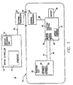
- FIGS 1 and 2 generally illustrate a conventional MRI injector system arrangement, such as is disclosed in U.S. Patent No. 5,494,036 to Uber et al.
- a magnetic resonance injector system is shown generally at 10.
- the MRI system includes a system controller 12 which incorporates a computer 14 and a battery charging unit 16.
- the system controller 12 is located externally of the imaging room 17, the imaging room being shielded from electromagnetic interference by a shield 18.
- Isolation can be achieved by completely enclosing the room with copper sheet material or some other suitable, conductive layer such as wire mesh.
- Communication line 20 connects the system controller 12 with an external infrared/optical communications transceiver 22.
- the shielded imaging room 17 also incorporates a patient viewing window 24 in the shield 18 which allows an operator to view the imaging room.
- the window 24 can be formed by sandwiching a wire mesh material (not shown) between sheets of glass or coating the window with a thin coating of conductive material such as gold (not shown) to maintain the continuity of the electromagnetic shield 18.
- An infrared/optical communications transceiver 26 is positioned internally of the imaging room 17 at the viewing window 24 opposite the external communications transceiver 22 such that the internal and external communications transceivers communicate with each other through the viewing window with no breach of the electromagnetic shield.
- a communications link 28 located within the shielded area connects the internal infrared/optical transceiver with an injection control unit 30.
- the injection control unit 30 is powered advantageously by rechargeable battery 32.
- the injection control unit 30 is powered advantageously by rechargeable battery 32.
- the injection control unit 30 also incorporates control circuitry which controls electric motors 35, 36 which are also located within the injection control unit.
- the injection control unit is contained within an electromagnetic shield 37 to prevent interference with the magnetic field used to generate the magnetic resonance image.
- the injection head unit should preferably be located in close proximity to the patient in order to decrease the distance that the contrast media fluid must travel from the contrast media injectors.
- the injection head unit 38 includes contrast media injection syringe and piston units 40, 42.
- the syringes 40, 42 are in operation communication with the electric motors in the injection control unit by flexible mechanical drive shafts 44, 46, respectively.
- the drive shafts are preferably made from a nonferrous metal such as hard brass.
- FIGS 3-6 Shown schematically in Figures 3-6 are various incarnations of a touch screen arrangement 200 that could be employed in accordance with at least one presently preferred embodiment of the present invention.
- a touch screen arrangement could be utilized in conjunction with a system controller 12 and computer 14 such as that described and illustrated hereinabove with respect to Figures 1 and 2.
- Display fields 210, 220 could also be touch fields used for desired purpose. For example, soft or hard key entry could be used, as well as trackball arrangements, mouse arrangements, or a cursor control touch pad (remote from the screen).
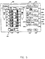
- touch screen arrangement 200 may permit for the display of a display field 210 corresponding to the available quantity of contrast medium, a variable column 212 of touch fields for facilitating the entry of control parameters relating to contrast medium, a variable column 214 of touch fields relating to flowrate, a variable column 216 of touch fields relating to volume, a variable column 218 of touch fields for facilitating the entry of control parameters relating to flushing medium and a display field 220 corresponding to the available quantity of flushing medium.
- Display fields 210, 220 could also be touch fields used for a desired purpose.
- contrast medium refers to essentially any suitable type of medium, as used in the medical arts, that is injected into a patient and, in the context of an imaging process (such as MR, angiography, ultrasound or CT), facilitates in highlighting selected areas of the patient's body while he/she is being scanned.
- imaging process such as MR, angiography, ultrasound or CT
- contrast medium also refers to other diagnostic or therapeutic agents for injection into patients.
- flush medium refers to essentially any suitable type of medium, such as a saline solution, that can be used to flush contrast medium from the tubing of an infusion system and that is well-suited for flowing through the patient's body so as to serve a useful supplementary purpose, such as keeping his/her veins open in preparation for another infusion of contrast medium.
- the touch screen arrangement 200 is preferably configured for permitting the operator to freely and flexibly incorporate phases of contact medium infusion and phases of flushing medium infusion with respect to one another in a manner that has hitherto apparently not been contemplated nor realized. (A definition of “phases” may be found in the "Background” section of this disclosure). Further, the present invention also contemplates “hold” and “pause” phases as discussed herebelow.
- Figure 3 illustrates one conceivable protocol that may be entered in accordance with an embodiment of the present invention.
- displays 210 and 220 show that 50 ml of contrast medium are available, as are 83 ml of flushing medium.
- the operator has selected the provision of two phases of contrast medium followed by one phase of flushing medium.
- the first phase of contrast medium infusion will have been set by activating the touch field 1 in column 212, followed by activating the corresponding entry fields in columns 214 and 216 and entering in them, respectively, the desired flowrate and desired volume to be administered to the patient.
- the entry of data can be accomplished by touching on a touch field (214 or 216), which could prompt the appearance of a key pad on the screen that would allow the entry of specific values in the fields 214, 216.
- a second phase of contrast medium infusion has also been set in similar manner, but this time by activating touch field 2 in column 212, followed by activating the corresponding entry fields in columns 214 and 216 and again entering in them, respectively, the desired flowrate and volume.
- the operator has selected a flushing medium infusion phase, this time by activating touch field 3 in column 218 and then entering the desired flow rate and volume parameters in the corresponding fields in columns 214 and 216.
- the result is a three-phase protocol that will result in the administration of: (1) a first phase of contrast medium infusion (10 ml) at 2.0 ml/s; (2) a second phase of contrast medium infusion (20 ml) at 1.0 ml/s; and (3) a phase of flushing medium infusion (25 ml) at 1.0 ml/s.
- Such a protocol might be desirable, for example, when it is desired that a patient first receive a first, quick infusion of contrast medium of smaller volume (i.e., a bolus of contrast medium) so as to accentuate (for imaging purposes) a small, particularized part of the body where such an infusion may be desirable (e.g., the kidneys), followed by a second, slower infusion of contrast medium of larger volume (e.g., a trickle or drip of contrast medium) that would be of use in a larger part of the body where a faster flowrate might not be needed (e.g., peripheral vascular regions of the legs).
- the flushing phase then, could subsequently be utilized for purposes such as those described heretofore.
- touch screen arrangement 200 may be so configured as to display only those data entry fields in columns 214, 216 that have been specifically activated by the operator (via activation of corresponding touch fields in columns 212, 218), so that there will be no data fields visible in columns 214, 216 corresponding to phases that are not to be used for a given protocol.
- Figure 3 shows that no data fields are visible in columns 214, 216 in correspondence with a fourth phase, since only three phases are being employed. Further, there will only preferably be one touch field in columns 212 and 218 visible beyond the number of phases that has already been chosen by the operator.
- the incrementally emerging data fields in columns 214 and 216 may assume different shades, in correspondence with the type of phase being employed.
- the data entry fields assume a darker shade in correspondence with a contrast medium infusion phase, while they assume a lighter shade in correspondence with a flushing medium infusion phase.
- the numbered touch fields in columns 212 and 218 may each preferably assume a corresponding shade in accordance with their being individually activated.
- fields 1 and 2 in column 212 are shaded in correspondence with their having been activated in the process of setting up two contrast medium infusion phases (following from their proximity to display field 210, which corresponds to contrast medium), while field 3 in column 218 is shaded in correspondence with its having been activated in the process of setting up a flushing medium infusion phase.
- neither of the fields 4 in columns 212, 218 are shaded since neither has been activated to set up a phase of any sort.
- duration display field 224 and a total volume display field 226. These preferably will serve as, respectively, a clock of elapsed time that starts from zero and spans the duration of the totality of the phases that have been entered and an indicator of the total volume of fluid (destined for the patient) that has been expended over the totality of the phases.
- duration display field 24 also preferably shows the projected total duration before injection starts
- volume display field 226 also preferably shows, at that time, the total projected volume to be expended.
- Figures 4-6 serve to further illustrate the versatility and flexibility afforded in accordance with at least one presently preferred embodiment of the present invention.
- Reference numerals in those figures relate to similar components referenced by similar numerals in Figure 3.
- the operator has chosen a first phase of contrast medium infusion, followed by a first phase of flushing medium infusion, followed by a second phase of contrast medium infusion, finally followed by a second phase of flushing medium infusion.
- Figure 5 illustrates a different protocol, but this time involving six phases. Particularly, the six phases illustrated are two separate contrast medium phases, followed by a flushing medium phase, followed again by two distinct contrast medium phases, finally followed by a flushing medium phase.
- Figure 6 illustrates a protocol involving a distinct "hold” phase in accordance with an embodiment of the present invention.
- the operator has selected a contrast medium phase followed by a flushing medium phase.
- a "hold” phase indicated at 244, in which, for an indefinite period of time (possibly capped automatically for safety reasons), the regulated administration of fluids may cease.
- the "hold” phase may be activated on touch screen arrangement 200 by pressing on icon 222, which would then produce a “hold” display field 244 that spans both columns 214, 216.
- the "hold” phase is then followed by a second contrast medium phase and a second flushing medium phase.
- the value of including a "hold” phase is that it permits some time for the operator to render supplementary judgements, following the administration of the phase(s) before the "hold", that could be of value when administering the phase(s) that occur(s) after the "hold".
- the operator may wish to first infuse a short bolus of contrast medium not for imaging purposes but for the purpose of determining the length of time (by any suitable means) that the bolus requires in order to reach a given target area in the patient's body. Once a flushing phase is completed, the "hold” may then take effect.
- the imaging scanner (not shown here) could be programmed to delay its imaging action for a period of time that corresponds to the "delay” that the "short bolus" required in order to reach the target area of the body.
- the scan delay i.e., the length of time that the scanner could "wait” before imaging the target area of the body
- the scan delay can be entered into a display field 228 by means of a touch field 228a suited for that purpose.
- the resulting bolus will be permitted to pass through the patient's system for a length of time corresponding to the "scan delay" before the scanner, conceivably prompted automatically via the scan delay clock in field 228 or perhaps manually by the operator (for example, upon hearing an audible signal), itself is activated as to image the target area of the patient.
- the scanner will be active for only such a length of time as is clearly necessary for imaging the target area, thus providing a highly desirable cost savings.
- a KVO ("keep vein open") display field 230 may show the status of "KVO", that is, whether there is a circulation of flushing medium (either continuously or in small intermittent bursts) in the patient's system for the purpose of maintaining a flow of some type in his/her veins and perhaps to show a countdown of the time remaining in such a state.
- the duration of "KVO" could preferably be capped, in correspondence with the actual quantity of flushing medium available (minus the flushing medium required for any subsequent flushing medium phase), automatically by the control system.
- the "arm injector" display field 232 and associated touch fields 232a and 232b serve the purpose of arming the injector and initiating the start of injection.
- the "display screen" display field 234 and associated touch fields 234a and 234b serve the purpose of accessing any configuration (set-up) information such as language (e.g ., English, German, French, Japanese, etc.) or KVO parameters or for reset ( e.g . zeroing) of the screen.
- the "history" display field 236 may serve the purpose of recalling past injection information that has been stored, while the "help” field 238 may serve the purpose of providing assistance to the operator in a manner similar to the "help" arrangements found on a typical computer or computer software system.
- the "protocol" display field 239 and associated touch fields 240, 242 may serve the purposes of the identification, storage and recall of user-defined (saved) injection programs or (factory) pre-loaded programs.
- the present invention in accordance with at least one presently preferred embodiment, has been described hereinabove primarily in connection with an MR injector system, it is to be understood that other applications are possible.
- CT, angiographic and ultrasound injectors to date have generally utilized only a single syringe, containing contrast medium, for administering solely contrast medium to a patient
- the present invention broadly contemplates the use of two syringes in such environments - one for contrast medium and the other for flushing medium.
- the present invention in accordance with at least one presently preferred embodiment, could be utilized in such a context in that the operator could administer a protocol involving essentially any desired order of contrast medium and flushing medium phases.
- a “pause” arrangement is also contemplated in accordance with at least one presently preferred embodiment of the present invention.
- a “pause” phase would essentially be similar to a “hold” phase in that it would represent a user-selected and programmed period of time in which no programmed injection of contrast medium or flushing medium is taking place. However, it would differ from a “hold” phase in the respect that it could essentially be a preprogrammed “hold” of limited duration that ends with an automatic transition to the next infusion phase (if any) in the protocol, whereas a “hold” phase would be of indefinite duration, with the protocol only to be reactivated by a manual prompt from the operator.
- "pause” phases have been known in conjunction with CT imaging arrangements, they are apparently not known in conjunction with MR imaging arrangements.
- an entire protocol can be stored and recalled for future use.
- the injector can reserve the flushing medium that is needed for an entire protocol and can alert the operator, before an injection commences, as to insufficient fluid volume.
- the protocol can shut off flow in a "KVO" state automatically in order to preserve any necessary flushing medium for a subsequent pre-programmed flushing phase.
- phase any type of phases, especially contrast medium and flushing medium phases, have essentially been described hereinabove as being linear in nature (i.e ., having a fixed flowrate over the duration of the phase), it should be understood that the present invention also broadly contemplates the programming and execution of phases that are not linear in nature.
- a contrast medium or flushing medium phase could represent a non-linear function, in which the flowrate could possibly be variable over the duration of the phase and could be programmed in by means of an equation, lookup table or other suitable arrangement.
- KVO it is even conceivable that short “bursts" of flushing medium could be emitted at a variable rate instead of a fixed rate.
- syringes have been specifically contemplated hereinabove for use in injection protocols, as a means for storing and administering contrasting medium or flushing medium, it is to be understood that other arrangements for this purpose are conceivable within the scope of the present invention, such as, for example, the use of peristaltic pumps.
- FIG. 7 schematically illustrates a scheme of illumination in association with a pair of syringes 440, 442.
- Syringes 440, 442 may, for the purposes of illustration, substantially correspond to syringes or injectors for containing contrast medium and flushing medium, respectively, substantially as described heretofore.
- Each syringe 440, 442 may have a corresponding illumination element 440a, 442a, respectively.
- the illumination elements 440a, 442a may be configured as to provide an indication of a status or condition associated with each syringe 440, 442, so as to allow for the visual assessment of such a status or condition from a distance.
- the illumination elements 440a, 442a could be configured for issuing light of different colors (e.g. green light for contrast medium and blue light for flushing medium) to permit one to easily distinguish between the two syringes.
- Figures 8-20 relate to modified touch screens in accordance with at least one presently preferred embodiment of the present invention.
- touch screen arrangement 500 may permit for the display of a display field 510 corresponding to the available quantity of contrast medium and a variable column 512 of touch fields for indicating the status of one or more phases that may be employed. Included also are a variable column 514 of touch fields relating to flowrate, a variable column 516 of touch fields relating to volume, and a display field 520 corresponding to the available quantity of flushing medium. Display fields 510, 520 could also be touch fields. Iconography 520a, adapted to appear and disappear within touch field 520, could indicate whether a "KVO" state is in effect.
- Figure 8 illustrates an "initiation screen" prior to entering a protocol.
- displays 510 and 520 show that 20 ml of contrast medium are available, as are 100 ml of flushing medium, while, in the protocol columns 514, 516, no flow rate has yet been established and a token volume of 1.0 ml of contrast medium is shown.
- a first phase of contrast medium infusion can be set by activating the uppermost touch field in column 512, and thence the corresponding entry fields in columns 514 and 516, followed by entering in the latter two entry fields, respectively, the desired flowrate and desired volume to be administered to the patient.
- the entry of data can be accomplished when, upon touching on a touch field (514 or 516), a key pad 560 appears on the screen that allows the entry of specific values in the fields 514, 516.
- Field 562 may be configured to convey to the operator a range of parameters that may be used in a given field in column 514 or 516. For this purpose, it is conceivable to draw attention to the field in question by highlighting it with a distinct color. As shown in Figure 8, for example, the topmost field in column 514 is highlighted in black.
- Figure 9 illustrates the entry of a protocol involving a contrast phase, a flushing phase and, in addition, a hold phase.
- the three phases that result are: (1) a phase of contrast medium infusion (15 ml) at 2.0 ml/s; (2) a phase of flushing medium infusion (20 ml) at 2.0 ml/s; and (3) a hold phase similar to that described heretofore.
- Figure 9 also illustrates an optional "keypad” 584 that permits a choice, for a given phase, of any of: a contrast phase, a flush phase, a hold or a pause. (The concept of "pause” has also been discussed heretofore.) "Delete” and “cancel” touch fields permit, respectively, erasing the previous entry or removing keypad 584 altogether.
- duration display field 564 and a total volume display field 566. These preferably will serve as, respectively, a clock of elapsed time that starts from zero and spans the duration of the totality of the phases that have been entered and an indicator of the total volume of fluid (destined for the patient) that has been expended over the totality of the phases.
- duration display field 564 also preferably shows the projected total duration before injection starts
- volume display field 566 also preferably shows, at that time, the total projected volume to be expended.
- Display field 566 may also preferably be configured to illustrate the total volume (of both contrast and flushing medium) already delivered.
- Figures 8 and 9 illustrate that three icons 568, 570, 572 may be employed.
- Icon 568 in the shape of a battery, indicates battery level. The number of horizontal bars within icon 568 indicate the useful life of the battery that remains.
- Icon 570 embodied as a check mark, can serve the function of an indicator for the status of the "check for air" function.
- Icon 572 on the other hand, embodied as opposing arrows, can confirm whether a digital interface with a scanner is intact.
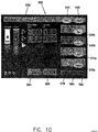
- Figure 10 illustrates another protocol. Entitled “renals”, the protocol set here involves an exemplary contrast phase and flush phase, as shown, for imaging the renals of a patient. Injection has not yet taken place.
- an "injection delay” can be entered into a display field 528 by means of a touch field 528a suited for that purpose.
- the "injection delay” corresponds to a period of time that elapses before the first phase of injection takes place.
- a KVO display field 530 may show the status of "KVO", particularly, a countdown of the time that remains in such a state.
- the duration of "KVO” could preferably be capped. Again, the rate, volume and frequency of delivery in "KVO" is fixed ahead of time but it could also be variably programmed by the operator, by any suitable means.
- the "arm injector" display field 574 and associated touch field 574a could serve the purpose of arming the injector in a manner to be described further below.
- the "history" display field 576 with associated touch field 576a may serve the purpose of recalling past injection information that has been stored.
- the "protocol" display field 539 and associated touch fields 540, 542 may serve the purposes of the identification, storage and recall of user-defined (saved) injection programs or (factory) pre-loaded programs.
- a "reset" touch field 578 could serve to return the touch screen 500 to an initial state, i.e., erase the parameters already entered and permit the operator to begin anew with entering a new protocol.
- a "setup" touch field 580 enables the user to access the setup screen, which allows the user to configure various details of the injection, e.g. language, programmable KVO and other configuration type setup features.
- a "help" touch field 582 could function similarly to the "help" touch field 238 discussed previously.
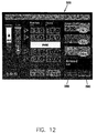
- Figures 11-20 illustrate different aspects of another protocol.
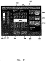
- the protocol has been given a name ("Dr. Smith's Study"), as shown in field 539. It should thus be appreciated that specific protocols may be selectively stored and recalled, in order to ensure that an operator does not need to constantly re-enter parameters for the same protocol if a protocol is to be repeated on several different occasions.
- a five-phase protocol has been called up, involving a contrast phase (1.0 ml at 1.0 ml/s), a flush phase (15.0 ml at 1.0 ml/s), a hold phase, a second contrast phase (10.0 ml at 3.0 ml/s) and a second flush phase (20.0 ml at 3.0 ml/s).
- "arming" the injection apparatus can be accomplished with the "arm injector" fields 574/574a discussed previously.
- touch field 574a may initially state “Arm” (see Figure 10)
- touching that touch field will preferably prompt the appearance of display field 586 and touch fields 588, 590, as shown.
- Touch fields 588, 590, respectively, permit the operator to indicate whether a single injection or a multiple injection, which is a repeat injection of the same protocol, are to be used.
- Display field 586 will preferably indicate which of the two aforementioned options (i.e., "single” or "multi") is in effect. Whereas Figure 11 shows that “single” has been chosen, Figure 12 (otherwise essentially the same view as Figure 11) shows that "multi" has been chosen.
- Figure 13 illustrates the appearance of a "query" button in column 512, thus permitting the operator to subsequently enter a new phase.
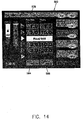
- Figure 14 is essentially the same view as Figure 13, but shows that a "pause” phase 592 has replaced the "hold” phase.
- a "pause” phase could represent a discrete, finite period of interruption that is predetermined.
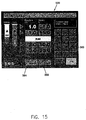
- Figure 15 is essentially the same view as Figure 13, but shows a mode similar to that illustrated by Figure 8, that is, an "entry” mode in which a given "protocol” field (in this case, the uppermost "flow rate” field in column 514) is highlighted as being “ready” for the entry of a new value.
- a display field 562 here indicating parameter limits.
- Figure 16 is essentially the same view as Figure 13 but conveys a state in which KVO is paused and an injection delay is taking place, prior to the start of the five protocol phases.
- the "protocol" fields in columns 514 and 516, including “hold” field 544 may be highlighted, perhaps with muted colors, and a display field 594 may appear to indicate that an injection delay is indeed taking place. Because the entire injection apparatus is now in an "active" mode, field 574a may now display a suitably highlighted “stop button” (perhaps in red with white lettering) that would permit the operator to abort the procedure before the first contrast phase begins.
- the operator may be apprised of the actual stage of the procedure being undertaking by suitably highlighting the "injection delay” field 528 as shown and indicating the time left in the injection delay.
- the "protocol" fields in columns 514 and 516, as well as hold field 544 may be in somewhat muted colors
- the "injection delay” field 528 may now be somewhat more bold in appearance, perhaps with a dark border as shown and with dark lettering on a bright background in the field itself
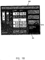
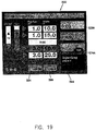
- Figures 17, 18 and 19 illustrate the possible status of touch screen 500 at various stages of the injection protocol being employed.
- a similar highlighting principle is utilized for such stages as for the "injection delay" stage as just described, that is, a field or fields relating to the actual stage or phase being undertaken is/are preferably highlighted in a manner that clearly indicates to the operator what is taking place.
- Figure 17 illustrates the possible status of touch screen 500 during the hold phase.
- the "hold" field 544 is highlighted with a dark border and dark lettering on a bright background.
- the phases already undertaken, on the other hand, are depicted in muted tones, while those which have not yet been undertaken preferably bear the "base” tones such as those depicted in Figure 13.
- Display field 594 preferably indicates that the hold phase is in effect.
- the syringe-shaped display fields 510, 520 preferably indicate visually the depletion of their respective reservoirs, both numerically and (via changing the relative shading within each field) graphically.
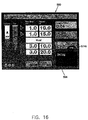
- Figure 18 illustrates that the second phase (in this case, a flushing phase) is in effect, via highlighting the appropriate fields in columns 512, 514 and 516, as well as the syringe-shaped display field 520. Also indicated, via field 594, is the fact that a temporary hold has been imposed within the actual phase itself. An operator may choose to do this, for instance, if a patient is experiencing discomfort and, e.g., needs to reposition the tubes, etc., that are delivering the flushing medium.
- a temporary hold has been imposed within the actual phase itself. An operator may choose to do this, for instance, if a patient is experiencing discomfort and, e.g., needs to reposition the tubes, etc., that are delivering the flushing medium.
- Figure 19 illustrates that the third phase (in this case, a contrast phase) is about to be in effect and that a scan delay (defined previously) is in effect.
- field 528 indicates a scan delay via the type of highlighting described previously.
- Figure 20 illustrates what may occur once the entire protocol is completed.
- a summary pop-up screen 596 may appear that provides various types of information on the phases of the protocol and of various parameters relating to it.
- a further touch field may be provided within the pop-up screen to permit the operator to complete the entire process by stopping "KVO".
- infusion and “injection”, and their grammatical derivations, are to be construed as being interchangeable and are meant to refer to essentially any of a wide range of arrangements for introducing fluid into a patient.
Landscapes
- Health & Medical Sciences (AREA)
- Vascular Medicine (AREA)
- Engineering & Computer Science (AREA)
- Anesthesiology (AREA)
- Biomedical Technology (AREA)
- Heart & Thoracic Surgery (AREA)
- Hematology (AREA)
- Life Sciences & Earth Sciences (AREA)
- Animal Behavior & Ethology (AREA)
- General Health & Medical Sciences (AREA)
- Public Health (AREA)
- Veterinary Medicine (AREA)
- Infusion, Injection, And Reservoir Apparatuses (AREA)
Description
- The present invention generally relates to powered injectors and syringes for use therewith, and more particularly, to apparatus for automatically controlling the same.
- A number of injector-actuated syringes and powered injectors for use in medical procedures such as angiography, computed tomography, ultrasound and NMRIMRI have been developed. U.S. Patent No. 4,006,736, for example, discloses an injector and syringe for injecting fluid into the vascular system of a human being or an animal. Typically, such injectors comprise drive members such as pistons that connect to a syringe plunger. For example, U.S. Patent No. 4,677,980, discloses an angiographic injector and syringe wherein the drive member of the injector can be connected to, or disconnected from, the syringe plunger at any point along the travel path of the plunger via a releasable mechanism. A front-loading syringe and injector system is also disclosed in U.S. Patent No. 5,383,858.
- U.S. Patent No. 5,494,036 discloses a patient infusion system adapted for use in MRI. The infusion system is designed to be substantially non-reactive with the magnetic field generated by the magnetic resonance imaging system for producing diagnostic images.
- Medrad has also developed a control arrangement ("SPECTRIS") for an MRI infusion system that uses two syringes, namely, one for the introduction of contrast medium into a patient and the other for a flushing medium. As is known conventionally, it is often desirable to flush from the tubing of an infusion system a residual quantity of contrast medium that remains there after a given infusion procedure, as contrast medium tends to be expensive and its efficient use, without waste, is often seen as a top priority. The "SPECTRIS" control arrangement will thus not only account for the residual contrast medium left in the tubing, and aim to use it in an infusion procedure, but will utilize a much cheaper flushing medium, such as a saline solution, in order to serve the purpose of pushing the residual contrast medium through the tubing and even through the patent's body (so as to "push" and deliver contrast medium to a region of interest in the body). Other advantageous purposes have also been recognized in connection with such flushing media, such as maintaining a flow through the patient's veins for a predetermined period of time in order that the veins will be better prepared to subsequently receive a new infusion of contrast medium.
- The "SPECTRIS" control arrangement is a pre-programmable arrangement for establishing a precise protocol for the infusion of contrast medium followed by flushing medium. At the time that the "SPECTRIS" system was established, needs in the industry were generally such that only some very simple protocols were desired. Thus, the "SPECTRIS" system addressed such needs by permitting protocols in which one or two "phases" of contrast medium took place followed by zero, one or two "phases" of flushing medium infusion. "Phase" refers to the application of a given quantity of a given medium at, for example, a fixed flowrate for a fixed period of time. Thus, up to two phases each of contrast medium and flushing medium, for example, were permitted by the "SPECTRIS" system, in order to provide a patient with different modes of infusion one after the other to serve particular purposes.
- Of late, however, some disadvantages have been noted in connection with the "SPECTRIS" control system and other related systems. Not the least of these is the lack of flexibility in developing and administering infusion protocols to a patient, as the "SPECTRIS" system would allow no more than two distinct phases for each medium, and no single phase of flushing medium infusion could take place between two different phases of contrast medium infusion.
- A further disadvantage has been recognized in that the aforementioned phases will typically be administered one after the other without the opportunity for an intermediate pause or hold between phases. This would appear to limit the convenience and utility of the system in question in many respects.
- Nemoto and Co., Ltd., of Tokyo, Japan has also developed a control system for an MR injector. However, this appears to be even less flexible than the "SPECTRIS" system in that only protocols consisting of no more than one contrast medium infusion and no more than one flushing medium infusion appear to be perrnitted.
- In the realm of CT (computed tomography) injection technology, Medrad has developed the "ENVISION" control system. As flushing media have generally not been hitherto employed in CT injector systems, the "ENVISION" system, much as any conventional CT injector control system, contemplates only the use of a single syringe for patient infusion, and solely for use with contrast medium. The "ENVISION" system permits protocols that employ up to eight different phases of contrast medium infusion, wherein each phase may employ a different infusion flowrate,infusion quantity and/or infusion duration. Pre-programmed pauses between infusion phases are also conceivable within such a context.
- US-A-5 806 519 discloses a fluid injection apparatus comprising two drive mechanisms, two fluid containers operably associated with the drive mechanisms, one fluid container containing contrast medium and the other fluid container containing a diluent, and a control device operably associated with the drive mechanisms. The control device is operable to selectively program a plurality of phases of an injection procedure, each of the phases comprising one of at least a contrast medium phase and a diluent phase. Furthermore, a static mixer is provided for mixing the contrast medium and the diluent, allowing for various contrast concentrations during said phases.
- EP-A-0 192 786 discloses an angiographic injector device for injecting contrast media into the vascular system of a patient, said device comprising means for holding a reservoir containing contrast media and including a discharge port through which the media is discharged, said means being a syringe.
- Evolving needs have thus been recognized in connection with providing an injection control system that is much more readily adaptable to a wider range of contexts.
- Generally, at least one presently preferred embodiment of the present invention broadly contemplates a fluid injection arrangement, in the context of patient imaging systems, in which phases of contrast medium injection and flushing medium injection can be freely and selectably ordered so as to make available to the operator and patient a vast array of possible protocols that has hitherto been essentially unattainable.
- The present invention also broadly contemplates the use of a "hold" phase, involving an indefinite pause between phases of a protocol, in connection with such imaging systems.
- Also broadly contemplated herein is the use of a "pause" phase in which a pause of fixed duration is pre-programmed into the protocols of MRI injector systems.
- The present invention and its presently preferred embodiments will be better understood by way of reference to the detailed disclosure herebelow and to the accompanying drawings, wherein:
- Figure 1 is a schematic depiction of a conventional magnetic resonance imaging (MRI) injector system arrangement;
- Figure 2 is a pictosranhic depiction of a conventional MRI injector system arrangement;
- Figures 3-6 are various depictions of a control screen arrangement for use with different protocols;
- Figure 7 is a schematic depiction of syringes with illumination elements;
- Figures 8 and 9 are depictions of a control screen arrangement for use with another protocol;
- Figure 10 is a depiction of a control screen arrangement for use with a further protocol; and
- Figures 11-20 are depictions of control screen arrangements for use with yet another protocol.
- Figures 1 and 2 generally illustrate a conventional MRI injector system arrangement, such as is disclosed in U.S. Patent No. 5,494,036 to Uber et al. A magnetic resonance injector system is shown generally at 10. The MRI system includes a
system controller 12 which incorporates acomputer 14 and abattery charging unit 16. Thesystem controller 12 is located externally of the imaging room 17, the imaging room being shielded from electromagnetic interference by ashield 18. - Isolation can be achieved by completely enclosing the room with copper sheet material or some other suitable, conductive layer such as wire mesh.
Communication line 20, connects thesystem controller 12 with an external infrared/optical communications transceiver 22. The shielded imaging room 17 also incorporates apatient viewing window 24 in theshield 18 which allows an operator to view the imaging room. Thewindow 24 can be formed by sandwiching a wire mesh material (not shown) between sheets of glass or coating the window with a thin coating of conductive material such as gold (not shown) to maintain the continuity of theelectromagnetic shield 18. - An infrared/
optical communications transceiver 26 is positioned internally of the imaging room 17 at theviewing window 24 opposite the external communications transceiver 22 such that the internal and external communications transceivers communicate with each other through the viewing window with no breach of the electromagnetic shield. Acommunications link 28 located within the shielded area connects the internal infrared/optical transceiver with aninjection control unit 30. Theinjection control unit 30 is powered advantageously byrechargeable battery 32. Theinjection control unit 30 is powered advantageously byrechargeable battery 32. Theinjection control unit 30 also incorporates control circuitry which controlselectric motors electromagnetic shield 37 to prevent interference with the magnetic field used to generate the magnetic resonance image. - The injection head unit should preferably be located in close proximity to the patient in order to decrease the distance that the contrast media fluid must travel from the contrast media injectors. The
injection head unit 38 includes contrast media injection syringe andpiston units syringes mechanical drive shafts - The disclosure now turns to an embodiment of the present invention, as illustrated in Figures 3-6, that could conceivably be employed in connection with a MRI injector system such as that shown in Figures 1 and 2 or with any other of a wide range of MR, CT, angiographic or ultrasound injector systems. These possible uses of at least one embodiment of the present invention are elucidated in greater detail herebelow.
- Shown schematically in Figures 3-6 are various incarnations of a
touch screen arrangement 200 that could be employed in accordance with at least one presently preferred embodiment of the present invention. As a non-restrictive example, such a touch screen arrangement could be utilized in conjunction with asystem controller 12 andcomputer 14 such as that described and illustrated hereinabove with respect to Figures 1 and 2. While a touch screen arrangement is contemplated in connection with Figures 3-6, it is to be understood that other types of data entry arrangements are conceivable that would achieve an equivalent purpose. Display fields 210, 220 could also be touch fields used for desired purpose. For example, soft or hard key entry could be used, as well as trackball arrangements, mouse arrangements, or a cursor control touch pad (remote from the screen). - As shown in Figure 3,
touch screen arrangement 200 may permit for the display of adisplay field 210 corresponding to the available quantity of contrast medium, a variable column 212 of touch fields for facilitating the entry of control parameters relating to contrast medium, avariable column 214 of touch fields relating to flowrate, avariable column 216 of touch fields relating to volume, avariable column 218 of touch fields for facilitating the entry of control parameters relating to flushing medium and adisplay field 220 corresponding to the available quantity of flushing medium. Display fields 210, 220 could also be touch fields used for a desired purpose. - The term "contrast medium", as employed herein, refers to essentially any suitable type of medium, as used in the medical arts, that is injected into a patient and, in the context of an imaging process (such as MR, angiography, ultrasound or CT), facilitates in highlighting selected areas of the patient's body while he/she is being scanned. In addition, the term "contrast medium", as employed herein, also refers to other diagnostic or therapeutic agents for injection into patients. The term "flushing medium", as employed herein, refers to essentially any suitable type of medium, such as a saline solution, that can be used to flush contrast medium from the tubing of an infusion system and that is well-suited for flowing through the patient's body so as to serve a useful supplementary purpose, such as keeping his/her veins open in preparation for another infusion of contrast medium.
- As will be appreciated throughout this disclosure, the
touch screen arrangement 200 is preferably configured for permitting the operator to freely and flexibly incorporate phases of contact medium infusion and phases of flushing medium infusion with respect to one another in a manner that has hitherto apparently not been contemplated nor realized. (A definition of "phases" may be found in the "Background" section of this disclosure). Further, the present invention also contemplates "hold" and "pause" phases as discussed herebelow. - Accordingly, Figure 3 illustrates one conceivable protocol that may be entered in accordance with an embodiment of the present invention. As shown, displays 210 and 220 show that 50 ml of contrast medium are available, as are 83 ml of flushing medium. Also, the operator has selected the provision of two phases of contrast medium followed by one phase of flushing medium.
- Preferably, the first phase of contrast medium infusion will have been set by activating the touch field 1 in column 212, followed by activating the corresponding entry fields in
columns fields - As shown, a second phase of contrast medium infusion has also been set in similar manner, but this time by activating
touch field 2 in column 212, followed by activating the corresponding entry fields incolumns - For the third phase, as shown in Figure 3, the operator has selected a flushing medium infusion phase, this time by activating
touch field 3 incolumn 218 and then entering the desired flow rate and volume parameters in the corresponding fields incolumns - The result is a three-phase protocol that will result in the administration of: (1) a first phase of contrast medium infusion (10 ml) at 2.0 ml/s; (2) a second phase of contrast medium infusion (20 ml) at 1.0 ml/s; and (3) a phase of flushing medium infusion (25 ml) at 1.0 ml/s. Such a protocol might be desirable, for example, when it is desired that a patient first receive a first, quick infusion of contrast medium of smaller volume (i.e., a bolus of contrast medium) so as to accentuate (for imaging purposes) a small, particularized part of the body where such an infusion may be desirable (e.g., the kidneys), followed by a second, slower infusion of contrast medium of larger volume (e.g., a trickle or drip of contrast medium) that would be of use in a larger part of the body where a faster flowrate might not be needed (e.g., peripheral vascular regions of the legs). The flushing phase, then, could subsequently be utilized for purposes such as those described heretofore.
- In a preferred embodiment of the present invention,
touch screen arrangement 200 may be so configured as to display only those data entry fields incolumns columns columns columns 212 and 218 visible beyond the number of phases that has already been chosen by the operator. Thus, as shown in Figure 3, three phases have been entered and thetouch fields 4 incolumns 212 and 218 are visible in preparation for possible activation of a fourth phase by the operator. In the meantime, a suitable icon 222 (preferably having use in connection with a "hold" phase, as described later) may be provided in place of the absent data entry fields incolumns - As shown, the incrementally emerging data fields in
columns columns 212 and 218 may each preferably assume a corresponding shade in accordance with their being individually activated. Thus, fields 1 and 2 in column 212 are shaded in correspondence with their having been activated in the process of setting up two contrast medium infusion phases (following from their proximity to displayfield 210, which corresponds to contrast medium), whilefield 3 incolumn 218 is shaded in correspondence with its having been activated in the process of setting up a flushing medium infusion phase. In contrast, neither of thefields 4 incolumns 212, 218 are shaded since neither has been activated to set up a phase of any sort. - The concept of incrementally emerging data fields in
columns - Also illustrated in Figure 3, inter alia, are a
duration display field 224 and a totalvolume display field 226. These preferably will serve as, respectively, a clock of elapsed time that starts from zero and spans the duration of the totality of the phases that have been entered and an indicator of the total volume of fluid (destined for the patient) that has been expended over the totality of the phases. As shown in Figure 3,duration display field 24 also preferably shows the projected total duration before injection starts, andvolume display field 226 also preferably shows, at that time, the total projected volume to be expended. - Figures 4-6 serve to further illustrate the versatility and flexibility afforded in accordance with at least one presently preferred embodiment of the present invention. Reference numerals in those figures relate to similar components referenced by similar numerals in Figure 3.
- In the protocol shown in Figure 4, the operator has chosen a first phase of contrast medium infusion, followed by a first phase of flushing medium infusion, followed by a second phase of contrast medium infusion, finally followed by a second phase of flushing medium infusion.
- Figure 5 illustrates a different protocol, but this time involving six phases. Particularly, the six phases illustrated are two separate contrast medium phases, followed by a flushing medium phase, followed again by two distinct contrast medium phases, finally followed by a flushing medium phase.
- Finally, Figure 6 illustrates a protocol involving a distinct "hold" phase in accordance with an embodiment of the present invention. As shown here, the operator has selected a contrast medium phase followed by a flushing medium phase. However, the operator has also now selected a "hold" phase, indicated at 244, in which, for an indefinite period of time (possibly capped automatically for safety reasons), the regulated administration of fluids may cease. The "hold" phase may be activated on
touch screen arrangement 200 by pressing onicon 222, which would then produce a "hold"display field 244 that spans bothcolumns - The value of including a "hold" phase is that it permits some time for the operator to render supplementary judgements, following the administration of the phase(s) before the "hold", that could be of value when administering the phase(s) that occur(s) after the "hold". As an example, and as can be appreciated from the protocol shown in Figure 6, the operator may wish to first infuse a short bolus of contrast medium not for imaging purposes but for the purpose of determining the length of time (by any suitable means) that the bolus requires in order to reach a given target area in the patient's body. Once a flushing phase is completed, the "hold" may then take effect. During the "hold", the imaging scanner (not shown here) could be programmed to delay its imaging action for a period of time that corresponds to the "delay" that the "short bolus" required in order to reach the target area of the body. In turn, the scan delay (i.e., the length of time that the scanner could "wait" before imaging the target area of the body) can be entered into a
display field 228 by means of atouch field 228a suited for that purpose. In this manner, when the time comes to administer the second contrast medium phase, the resulting bolus will be permitted to pass through the patient's system for a length of time corresponding to the "scan delay" before the scanner, conceivably prompted automatically via the scan delay clock infield 228 or perhaps manually by the operator (for example, upon hearing an audible signal), itself is activated as to image the target area of the patient. In this manner, the scanner will be active for only such a length of time as is clearly necessary for imaging the target area, thus providing a highly desirable cost savings. - Other touch fields and display fields may be provided within
touch screen arrangement 200. As shown in Figures 3-6, a KVO ("keep vein open")display field 230 may show the status of "KVO", that is, whether there is a circulation of flushing medium (either continuously or in small intermittent bursts) in the patient's system for the purpose of maintaining a flow of some type in his/her veins and perhaps to show a countdown of the time remaining in such a state. The duration of "KVO" could preferably be capped, in correspondence with the actual quantity of flushing medium available (minus the flushing medium required for any subsequent flushing medium phase), automatically by the control system. Thus, automatic shutoff could take place when the reservoir of available flushing medium has decreased to a point at which, with further depletion, there would not be a sufficient amount of flushing medium for a subsequent flushing medium phase or phases. It will be appreciated that "KVO" is not so much a flushing phase per se but instead is a "maintenance" phase in which the patient's veins are maintained in a relatively open state in preparation for the subsequent administration of contrast medium, or possibly even for other reasons. "KVO" could thus well take place during a "hold" phase so that, for example, the patient's veins could remain relatively open and free while the aforementioned intermediate calculations, etc., are taking place. Normally, the rate, volume and frequency of delivery in "KVO" is fixed ahead of time but it could also be variably programmed by the operator, by any suitable means. - The "arm injector"
display field 232 and associatedtouch fields - On the other hand, the "display screen"
display field 234 and associatedtouch fields - The "history"
display field 236 may serve the purpose of recalling past injection information that has been stored, while the "help"field 238 may serve the purpose of providing assistance to the operator in a manner similar to the "help" arrangements found on a typical computer or computer software system. - Firially, the "protocol"
display field 239 and associated touch fields 240, 242 may serve the purposes of the identification, storage and recall of user-defined (saved) injection programs or (factory) pre-loaded programs. - Although the present invention, in accordance with at least one presently preferred embodiment, has been described hereinabove primarily in connection with an MR injector system, it is to be understood that other applications are possible. For example, while it is known that CT, angiographic and ultrasound injectors to date have generally utilized only a single syringe, containing contrast medium, for administering solely contrast medium to a patient, the present invention broadly contemplates the use of two syringes in such environments - one for contrast medium and the other for flushing medium. Thus, it is contemplated that the present invention, in accordance with at least one presently preferred embodiment, could be utilized in such a context in that the operator could administer a protocol involving essentially any desired order of contrast medium and flushing medium phases.
- A "pause" arrangement is also contemplated in accordance with at least one presently preferred embodiment of the present invention. A "pause" phase would essentially be similar to a "hold" phase in that it would represent a user-selected and programmed period of time in which no programmed injection of contrast medium or flushing medium is taking place. However, it would differ from a "hold" phase in the respect that it could essentially be a preprogrammed "hold" of limited duration that ends with an automatic transition to the next infusion phase (if any) in the protocol, whereas a "hold" phase would be of indefinite duration, with the protocol only to be reactivated by a manual prompt from the operator. Although "pause" phases have been known in conjunction with CT imaging arrangements, they are apparently not known in conjunction with MR imaging arrangements.
- It should be appreciated that the arrangements described hereinabove afford a degree of flexibility and versatility in programming an injection protocol than apparently has been hitherto realized. One distinct advantage inherent in such arrangements is their adaptability to foreseeable changes in the injection arts that may occur in the future, such as the development of new contrast media or increases in the efficiency of imaging scanners. For instance, it is conceivable that a different type of contrast medium might necessitate its injection into a patient via a much different protocol than might now normally be used with existing contrast media. Increases in imaging speed might also result in the need for vastly different types of protocols than are available on conventional equipment at present.
- It will be appreciated that the flexibility and versatility achieved in accordance with at least one presently preferred embodiment of the present invention, with the use of an automatic arrangement, far outstrips any flexibility and versatility that might be gained through certain uses of existing injection arrangements. For example, although it is conceivable to employ two or more "SPECTRIS" systems for the purpose of executing a composite protocol, made up of separate protocols from the different systems, that might reflect a higher degree of versatility (e.g., by enabling the execution of a second contrast medium phase after a flushing medium phase), it will be appreciated that such an arrangement would be cumbersome, difficult to manage, and possibly inaccurate, in that one or more operators would need to ensure that one phase on one system starts immediately after another phase on another system. Manual injection is, of course, also possible, even to such an extent that different injections, representing distinctly different contrast medium and flushing medium phases, could be executed one after the other by one or more medical personnel. Again, though, such an arrangement would appear to prone to the potential of great inaccuracy, not only in terms of the timing of the successive injections but also in terms of the flowrates being used and the difficulty in keeping them constant over the duration of each phase (if indeed constant flowrates are desired).
- Several other advantages would appear to be attainable in accordance with at least one presently preferred embodiment of the present invention. For example, an entire protocol can be stored and recalled for future use. The injector can reserve the flushing medium that is needed for an entire protocol and can alert the operator, before an injection commences, as to insufficient fluid volume. Moreover, in a multi-phased protocol that includes flushing and has an intermediate "hold" phase, the protocol can shut off flow in a "KVO" state automatically in order to preserve any necessary flushing medium for a subsequent pre-programmed flushing phase.
- Although a maximum of six phases for one protocol has been described hereabove, it will be appreciated that the present invention broadly contemplates that no maximum on the number of phases in a protocol necessarily need be imposed.
- Although all types of phases, especially contrast medium and flushing medium phases, have essentially been described hereinabove as being linear in nature (i.e., having a fixed flowrate over the duration of the phase), it should be understood that the present invention also broadly contemplates the programming and execution of phases that are not linear in nature. For example, it is conceivable that a contrast medium or flushing medium phase (and possibly even a "KVO" phase) could represent a non-linear function, in which the flowrate could possibly be variable over the duration of the phase and could be programmed in by means of an equation, lookup table or other suitable arrangement. In the case of "KVO", it is even conceivable that short "bursts" of flushing medium could be emitted at a variable rate instead of a fixed rate.
- Although syringes have been specifically contemplated hereinabove for use in injection protocols, as a means for storing and administering contrasting medium or flushing medium, it is to be understood that other arrangements for this purpose are conceivable within the scope of the present invention, such as, for example, the use of peristaltic pumps.
- As discussed herebelow, some additional refinements are broadly contemplated in accordance with at least one presently preferred embodiment of the present invention.
- Figure 7 schematically illustrates a scheme of illumination in association with a pair of
syringes Syringes - Each
syringe syringe - Figures 8-20 relate to modified touch screens in accordance with at least one presently preferred embodiment of the present invention.
- While several components associated with the touch screens illustrated in Figures 8-20 are similar to those illustrated in Figures 3-6, other new or modified components are also contemplated, as discussed herebelow.
- As shown in Figure 8,
touch screen arrangement 500 may permit for the display of a display field 510 corresponding to the available quantity of contrast medium and a variable column 512 of touch fields for indicating the status of one or more phases that may be employed. Included also are a variable column 514 of touch fields relating to flowrate, a variable column 516 of touch fields relating to volume, and a display field 520 corresponding to the available quantity of flushing medium. Display fields 510, 520 could also be touch fields. Iconography 520a, adapted to appear and disappear within touch field 520, could indicate whether a "KVO" state is in effect. - Essentially, Figure 8 illustrates an "initiation screen" prior to entering a protocol. As shown, displays 510 and 520 show that 20 ml of contrast medium are available, as are 100 ml of flushing medium, while, in the protocol columns 514, 516, no flow rate has yet been established and a token volume of 1.0 ml of contrast medium is shown.
- Preferably, a first phase of contrast medium infusion can be set by activating the uppermost touch field in column 512, and thence the corresponding entry fields in columns 514 and 516, followed by entering in the latter two entry fields, respectively, the desired flowrate and desired volume to be administered to the patient. The entry of data can be accomplished when, upon touching on a touch field (514 or 516), a
key pad 560 appears on the screen that allows the entry of specific values in the fields 514, 516. -
Field 562 may be configured to convey to the operator a range of parameters that may be used in a given field in column 514 or 516. For this purpose, it is conceivable to draw attention to the field in question by highlighting it with a distinct color. As shown in Figure 8, for example, the topmost field in column 514 is highlighted in black. - Figure 9 illustrates the entry of a protocol involving a contrast phase, a flushing phase and, in addition, a hold phase. Thus, the three phases that result are: (1) a phase of contrast medium infusion (15 ml) at 2.0 ml/s; (2) a phase of flushing medium infusion (20 ml) at 2.0 ml/s; and (3) a hold phase similar to that described heretofore.
- Figure 9 also illustrates an optional "keypad" 584 that permits a choice, for a given phase, of any of: a contrast phase, a flush phase, a hold or a pause. (The concept of "pause" has also been discussed heretofore.) "Delete" and "cancel" touch fields permit, respectively, erasing the previous entry or removing keypad 584 altogether.
- Also illustrated in Figures 8 and 9, inter alia, are a
duration display field 564 and a totalvolume display field 566. These preferably will serve as, respectively, a clock of elapsed time that starts from zero and spans the duration of the totality of the phases that have been entered and an indicator of the total volume of fluid (destined for the patient) that has been expended over the totality of the phases. As shown in Figures 8 and 9,duration display field 564 also preferably shows the projected total duration before injection starts, andvolume display field 566 also preferably shows, at that time, the total projected volume to be expended.Display field 566 may also preferably be configured to illustrate the total volume (of both contrast and flushing medium) already delivered. - Figures 8 and 9 illustrate that three
icons Icon 568, in the shape of a battery, indicates battery level. The number of horizontal bars withinicon 568 indicate the useful life of the battery that remains.Icon 570, embodied as a check mark, can serve the function of an indicator for the status of the "check for air" function.Icon 572, on the other hand, embodied as opposing arrows, can confirm whether a digital interface with a scanner is intact. - Figure 10 illustrates another protocol. Entitled "renals", the protocol set here involves an exemplary contrast phase and flush phase, as shown, for imaging the renals of a patient. Injection has not yet taken place.
- As shown in Figure 10, other touch fields and display fields may be provided within
touch screen arrangement 500. For instance, an "injection delay" can be entered into adisplay field 528 by means of a touch field 528a suited for that purpose. The "injection delay" corresponds to a period of time that elapses before the first phase of injection takes place. - A KVO display field 530 may show the status of "KVO", particularly, a countdown of the time that remains in such a state. As discussed previously, the duration of "KVO" could preferably be capped. Again, the rate, volume and frequency of delivery in "KVO" is fixed ahead of time but it could also be variably programmed by the operator, by any suitable means.
- The "arm injector" display field 574 and associated touch field 574a could serve the purpose of arming the injector in a manner to be described further below.
- The "history" display field 576 with associated touch field 576a may serve the purpose of recalling past injection information that has been stored.
- The "protocol"
display field 539 and associated touch fields 540, 542 may serve the purposes of the identification, storage and recall of user-defined (saved) injection programs or (factory) pre-loaded programs. - A "reset"
touch field 578 could serve to return thetouch screen 500 to an initial state, i.e., erase the parameters already entered and permit the operator to begin anew with entering a new protocol. - A "setup"
touch field 580 enables the user to access the setup screen, which allows the user to configure various details of the injection, e.g. language, programmable KVO and other configuration type setup features. - A "help"
touch field 582 could function similarly to the "help"touch field 238 discussed previously. - Figures 11-20 illustrate different aspects of another protocol. In this instance, the protocol has been given a name ("Dr. Smith's Study"), as shown in
field 539. It should thus be appreciated that specific protocols may be selectively stored and recalled, in order to ensure that an operator does not need to constantly re-enter parameters for the same protocol if a protocol is to be repeated on several different occasions. - As shown in Figure 11, a five-phase protocol has been called up, involving a contrast phase (1.0 ml at 1.0 ml/s), a flush phase (15.0 ml at 1.0 ml/s), a hold phase, a second contrast phase (10.0 ml at 3.0 ml/s) and a second flush phase (20.0 ml at 3.0 ml/s).
- Preferably, "arming" the injection apparatus can be accomplished with the "arm injector" fields 574/574a discussed previously. Whereas touch field 574a may initially state "Arm" (see Figure 10), touching that touch field will preferably prompt the appearance of display field 586 and
touch fields - Display field 586 will preferably indicate which of the two aforementioned options (i.e., "single" or "multi") is in effect. Whereas Figure 11 shows that "single" has been chosen, Figure 12 (otherwise essentially the same view as Figure 11) shows that "multi" has been chosen.
- Figure 13 illustrates the appearance of a "query" button in column 512, thus permitting the operator to subsequently enter a new phase.
- Figure 14 is essentially the same view as Figure 13, but shows that a "pause" phase 592 has replaced the "hold" phase. As discussed previously, a "pause" phase could represent a discrete, finite period of interruption that is predetermined.
- Figure 15 is essentially the same view as Figure 13, but shows a mode similar to that illustrated by Figure 8, that is, an "entry" mode in which a given "protocol" field (in this case, the uppermost "flow rate" field in column 514) is highlighted as being "ready" for the entry of a new value. Thus, there is also a
display field 562 here indicating parameter limits. - Figure 16 is essentially the same view as Figure 13 but conveys a state in which KVO is paused and an injection delay is taking place, prior to the start of the five protocol phases. To indicate this effect, the "protocol" fields in columns 514 and 516, including "hold" field 544, may be highlighted, perhaps with muted colors, and a
display field 594 may appear to indicate that an injection delay is indeed taking place. Because the entire injection apparatus is now in an "active" mode, field 574a may now display a suitably highlighted "stop button" (perhaps in red with white lettering) that would permit the operator to abort the procedure before the first contrast phase begins. On the other hand, the operator may be apprised of the actual stage of the procedure being undertaking by suitably highlighting the "injection delay"field 528 as shown and indicating the time left in the injection delay. Whereas the "protocol" fields in columns 514 and 516, as well as hold field 544, may be in somewhat muted colors, the "injection delay"field 528 may now be somewhat more bold in appearance, perhaps with a dark border as shown and with dark lettering on a bright background in the field itself - Figures 17, 18 and 19 illustrate the possible status of
touch screen 500 at various stages of the injection protocol being employed. Preferably, a similar highlighting principle is utilized for such stages as for the "injection delay" stage as just described, that is, a field or fields relating to the actual stage or phase being undertaken is/are preferably highlighted in a manner that clearly indicates to the operator what is taking place. - Thus, Figure 17 illustrates the possible status of
touch screen 500 during the hold phase. In this case, the "hold" field 544 is highlighted with a dark border and dark lettering on a bright background. The phases already undertaken, on the other hand, are depicted in muted tones, while those which have not yet been undertaken preferably bear the "base" tones such as those depicted in Figure 13.Display field 594 preferably indicates that the hold phase is in effect. Also, as shown, the syringe-shaped display fields 510, 520 preferably indicate visually the depletion of their respective reservoirs, both numerically and (via changing the relative shading within each field) graphically. - Figure 18 illustrates that the second phase (in this case, a flushing phase) is in effect, via highlighting the appropriate fields in columns 512, 514 and 516, as well as the syringe-shaped display field 520. Also indicated, via
field 594, is the fact that a temporary hold has been imposed within the actual phase itself. An operator may choose to do this, for instance, if a patient is experiencing discomfort and, e.g., needs to reposition the tubes, etc., that are delivering the flushing medium. - Figure 19 illustrates that the third phase (in this case, a contrast phase) is about to be in effect and that a scan delay (defined previously) is in effect. Thus,
field 528 indicates a scan delay via the type of highlighting described previously. - Finally, Figure 20 illustrates what may occur once the entire protocol is completed. Preferably, a summary pop-up
screen 596 may appear that provides various types of information on the phases of the protocol and of various parameters relating to it. A further touch field may be provided within the pop-up screen to permit the operator to complete the entire process by stopping "KVO". - In the context of the present disclosure, the terms "infusion" and "injection", and their grammatical derivations, are to be construed as being interchangeable and are meant to refer to essentially any of a wide range of arrangements for introducing fluid into a patient.
- If not otherwise stated herein, it may be assumed that all components and/or processes described heretofore may, if appropriate, be considered to be interchangeable with similar components and/or processes disclosed elsewhere in the specification, unless an express indication is made to the contrary.
- If not otherwise stated herein, any and all patents, patent publications, articles and other printed publications discussed or mentioned herein are hereby incorporated by reference as if set forth in their entirety herein.
- It should be appreciated that the apparatus and method of the present invention may be configured and conducted as appropriate for any context at hand. The embodiments described above are to be considered in all respects only as illustrative and not restrictive. The scope of the invention is defined by the following claims rather than the foregoing description.
Claims (9)
- A fluid injection apparatus comprising:at least one drive mechanism (44, 46);at least two fluid containers (40, 42) operably associated with the at least one drive mechanism (44, 46), one fluid container containing a contrast medium and the other fluid container containing a flushing medium; anda control device (12) operably associated with the at least one drive mechanism (44, 46) and operable to selectively program a plurality of phases of an injection procedure,characterised in that a first phase comprises one of a contrast medium phase and a flushing medium phase, a second phase comprises one of a contrast medium phase and a flushing medium phase and a third phase comprises a pre-programmed hold phase or a pre-programmed pause phase, the pre-programmed hold phase (240) or the pre-programmed pause phase being programmed to occur between the first and second phases,wherein the hold phase or the pause phase allows an operator to modify one ore more injection parameters of a subsequent phase.
- The apparatus of Claim 1 wherein the hold phase is of indefinite duration.
- The apparatus of Claim 1 or 2 wherein KVO occurs during the hold phase.
- The apparatus of Claim 1 wherein the pause phase is programmable for a fixed duration of time.
- The apparatus of Claim 1 or 4 wherein the second phase automatically commences after the end of the pause phase.
- The apparatus of any one of Claims 1 to 5 wherein at least one of the two fluid containers (40, 42) comprises a syringe.
- The apparatus of any one of Claims 1 to 6 wherein a first phase comprises a flushing medium phase and a second phase comprises a contrast medium phase.
- The apparatus of any one of Claims 1 to 7 wherein each of the contrast medium and flushing medium phases is defined by at least two injection parameters selected from fluid flow rate (214), fluid volume (216) and injection duration (224).
- The apparatus of any one of Claims 1 to 8 wherein the control device (12) is operable to selectively program a KVO phase.
Applications Claiming Priority (3)
| Application Number | Priority Date | Filing Date | Title |
|---|---|---|---|
| US365278 | 1989-06-12 | ||
| US09/365,278 US6339718B1 (en) | 1999-07-30 | 1999-07-30 | Programmable injector control |
| PCT/US2000/020770 WO2001008730A1 (en) | 1999-07-30 | 2000-07-28 | Programmable injector control |
Publications (2)
| Publication Number | Publication Date |
|---|---|
| EP1202760A1 EP1202760A1 (en) | 2002-05-08 |
| EP1202760B1 true EP1202760B1 (en) | 2006-02-15 |
Family
ID=23438206
Family Applications (1)
| Application Number | Title | Priority Date | Filing Date |
|---|---|---|---|
| EP00952314A Expired - Lifetime EP1202760B1 (en) | 1999-07-30 | 2000-07-28 | Programmable injector control |
Country Status (5)
| Country | Link |
|---|---|
| US (6) | US6339718B1 (en) |
| EP (1) | EP1202760B1 (en) |
| JP (1) | JP4299482B2 (en) |
| DE (1) | DE60026036T2 (en) |
| WO (1) | WO2001008730A1 (en) |
Families Citing this family (252)
| Publication number | Priority date | Publication date | Assignee | Title |
|---|---|---|---|---|
| US6099502A (en) * | 1995-04-20 | 2000-08-08 | Acist Medical Systems, Inc. | Dual port syringe |
| US20030028145A1 (en) * | 1995-04-20 | 2003-02-06 | Duchon Douglas J. | Angiographic injector system with multiple processor redundancy |
| US7267666B1 (en) * | 1995-04-20 | 2007-09-11 | Acist Medical Systems, Inc. | Angiographic injector system with multiple processor redundancy |
| US6656157B1 (en) * | 1995-04-20 | 2003-12-02 | Acist Medical Systems, Inc. | Infinitely refillable syringe |
| US8082018B2 (en) * | 1995-04-20 | 2011-12-20 | Acist Medical Systems, Inc. | System and method for multiple injection procedures on heart vessels |
| DE69831596T2 (en) * | 1997-11-07 | 2006-06-22 | ACIST Medical Systems, Inc., Eden Prairie | ANGIOGRAPHY SYRINGE WITH MULTILEDREDUNDANT PROCESSORS |
| DE19859811C2 (en) * | 1998-12-23 | 2001-05-10 | Hilekes Guido | Contrast agent injection system |
| AU4185600A (en) * | 1999-04-01 | 2000-10-23 | Acist Medical Systems, Inc. | An integrated medical information management and medical device control system and method |
| US6339718B1 (en) | 1999-07-30 | 2002-01-15 | Medrad, Inc. | Programmable injector control |
| US20030216643A1 (en) * | 1999-07-30 | 2003-11-20 | Zatezalo Douglas M. | Programmable injector control |
| AU6632600A (en) * | 1999-08-20 | 2001-03-19 | Acist Medical Systems, Inc. | Apparatus and method of detecting fluid |
| US6669679B1 (en) | 2000-01-07 | 2003-12-30 | Acist Medical Systems, Inc. | Anti-recoil catheter |
| US6626862B1 (en) * | 2000-04-04 | 2003-09-30 | Acist Medical Systems, Inc. | Fluid management and component detection system |
| US6673048B1 (en) | 2000-05-24 | 2004-01-06 | Acist Medical Systems, Inc. | Pressure sleeve assembly |
| US6558352B1 (en) * | 2000-05-30 | 2003-05-06 | Verilogik, Inc. | System and method for variable dosage medicine delivery |
| DE10030620A1 (en) * | 2000-06-28 | 2002-01-17 | Karlsruhe Forschzent | Device for injecting medical preparations under CT / MRI control |
| AUPQ867900A0 (en) * | 2000-07-10 | 2000-08-03 | Medrad, Inc. | Medical injector system |
| EP1897574B1 (en) * | 2000-07-20 | 2012-09-05 | ACIST Medical Systems, Inc. | Syringe plunger locking mechanism |
| WO2005119025A2 (en) | 2004-06-01 | 2005-12-15 | Spectrum Dynamics Llc | Radioactive-emission-measurement optimization to specific body structures |
| US8565860B2 (en) * | 2000-08-21 | 2013-10-22 | Biosensors International Group, Ltd. | Radioactive emission detector equipped with a position tracking system |
| US8489176B1 (en) | 2000-08-21 | 2013-07-16 | Spectrum Dynamics Llc | Radioactive emission detector equipped with a position tracking system and utilization thereof with medical systems and in medical procedures |
| US8909325B2 (en) * | 2000-08-21 | 2014-12-09 | Biosensors International Group, Ltd. | Radioactive emission detector equipped with a position tracking system and utilization thereof with medical systems and in medical procedures |
| US7094216B2 (en) | 2000-10-18 | 2006-08-22 | Medrad, Inc. | Injection system having a pressure isolation mechanism and/or a handheld controller |
| WO2002064195A2 (en) * | 2001-02-14 | 2002-08-22 | Acist Medical Systems, Inc. | Catheter fluid control system |
| US7566320B2 (en) * | 2001-02-14 | 2009-07-28 | Acist Medical Systems, Inc. | Fluid injector system |
| WO2002065114A2 (en) * | 2001-02-15 | 2002-08-22 | Acist Medical Systems, Inc. | Systems and methods for detection and measurement of elements in a medium |
| US6817986B2 (en) * | 2001-04-13 | 2004-11-16 | Avant Medical Corp. | Jet injector with data logging system for use in compliance and dose monitoring programs |
| US7308300B2 (en) * | 2001-05-30 | 2007-12-11 | Acist Medical Systems, Inc. | Medical injection system |
| US7389788B2 (en) * | 2001-12-07 | 2008-06-24 | Acist Medical Systems, Inc. | Low pressure measurement devices in high pressure environments |
| US6880808B2 (en) | 2002-05-03 | 2005-04-19 | Acist Medical Systems, Inc. | Gamma-stable high pressure stopcock |
| US7553294B2 (en) * | 2002-05-30 | 2009-06-30 | Medrad, Inc. | Syringe plunger sensing mechanism for a medical injector |
| US7018361B2 (en) * | 2002-06-14 | 2006-03-28 | Baxter International Inc. | Infusion pump |
| US7553295B2 (en) | 2002-06-17 | 2009-06-30 | Iradimed Corporation | Liquid infusion apparatus |
| US7404809B2 (en) | 2004-10-12 | 2008-07-29 | Iradimed Corporation | Non-magnetic medical infusion device |
| US7267661B2 (en) * | 2002-06-17 | 2007-09-11 | Iradimed Corporation | Non-magnetic medical infusion device |
| AU2011205122B2 (en) * | 2002-08-02 | 2013-10-31 | Liebel-Flarsheim Company | Injector |
| US6929619B2 (en) * | 2002-08-02 | 2005-08-16 | Liebel-Flarshiem Company | Injector |
| US7224143B2 (en) * | 2002-11-27 | 2007-05-29 | Medrad, Inc. | Continuous battery charger system |
| JP4731795B2 (en) | 2003-02-18 | 2011-07-27 | 株式会社根本杏林堂 | Chemical injection device |
| JP2006522658A (en) * | 2003-04-08 | 2006-10-05 | メドラッド インコーポレーテッド | Fluid transport system, fluid transport device, and method for transporting hazardous fluid |
| CN100536943C (en) | 2003-07-18 | 2009-09-09 | 株式会社根本杏林堂 | Liquid injector displaying input injection conditions as images |
| JP4473543B2 (en) * | 2003-09-05 | 2010-06-02 | 株式会社東芝 | Ultrasonic diagnostic equipment |
| US9123077B2 (en) | 2003-10-07 | 2015-09-01 | Hospira, Inc. | Medication management system |
| US8065161B2 (en) | 2003-11-13 | 2011-11-22 | Hospira, Inc. | System for maintaining drug information and communicating with medication delivery devices |
| USD1031029S1 (en) | 2003-11-25 | 2024-06-11 | Bayer Healthcare Llc | Syringe plunger |
| US7666169B2 (en) | 2003-11-25 | 2010-02-23 | Medrad, Inc. | Syringe and syringe plungers for use with medical injectors |
| WO2005054999A2 (en) * | 2003-11-26 | 2005-06-16 | E-Z-Em, Inc. | Device, method, and computer program product for dispensing media as part of a medical procedure |
| US9470801B2 (en) * | 2004-01-13 | 2016-10-18 | Spectrum Dynamics Llc | Gating with anatomically varying durations |
| US8571881B2 (en) * | 2004-11-09 | 2013-10-29 | Spectrum Dynamics, Llc | Radiopharmaceutical dispensing, administration, and imaging |
| US10964075B2 (en) | 2004-01-13 | 2021-03-30 | Spectrum Dynamics Llc | Gating with anatomically varying durations |
| US9040016B2 (en) * | 2004-01-13 | 2015-05-26 | Biosensors International Group, Ltd. | Diagnostic kit and methods for radioimaging myocardial perfusion |
| WO2005067383A2 (en) * | 2004-01-13 | 2005-07-28 | Spectrum Dynamics Llc | Multi-dimensional image reconstruction |
| US8586932B2 (en) | 2004-11-09 | 2013-11-19 | Spectrum Dynamics Llc | System and method for radioactive emission measurement |
| JP5148881B2 (en) * | 2004-02-11 | 2013-02-20 | アシスト・メディカル・システムズ,インコーポレイテッド | Method system and apparatus for operating medical injectors and diagnostic imaging apparatus |
| US7491191B2 (en) * | 2004-02-13 | 2009-02-17 | Liebel-Flarsheim Company | Keep vein open method and injector with keep vein open function |
| US9627097B2 (en) * | 2004-03-02 | 2017-04-18 | General Electric Company | Systems, methods and apparatus for infusion of radiopharmaceuticals |
| US8452380B2 (en) * | 2004-04-22 | 2013-05-28 | Acist Medical Systems, Inc. | Interface device and protocol |
| EP1750792B1 (en) * | 2004-05-04 | 2013-04-10 | Acist Medical Systems, Inc. | Method and system for implementing a graphical user interface for a multi-fluid injection device |
| US20060079842A1 (en) * | 2004-10-13 | 2006-04-13 | Liebel-Flarsheim Company | Powerhead control in a power injection system |
| US8900187B2 (en) * | 2004-10-13 | 2014-12-02 | Mallinckrodt Llc | Powerhead control in a power injection system |
| US7507221B2 (en) | 2004-10-13 | 2009-03-24 | Mallinckrodt Inc. | Powerhead of a power injection system |
| US20080004507A1 (en) * | 2004-10-27 | 2008-01-03 | E-Z-Em, Inc. | Data collection device, system, method, and computer program product for collecting data related to the dispensing of contrast media |
| HUE044401T2 (en) * | 2004-10-27 | 2019-10-28 | Acist Medical Sys Inc | Data collection device, system, method, and computer program product for collecting data related to the dispensing of contrast media |
| US8615405B2 (en) * | 2004-11-09 | 2013-12-24 | Biosensors International Group, Ltd. | Imaging system customization using data from radiopharmaceutical-associated data carrier |
| US8423125B2 (en) | 2004-11-09 | 2013-04-16 | Spectrum Dynamics Llc | Radioimaging |
| US8606349B2 (en) | 2004-11-09 | 2013-12-10 | Biosensors International Group, Ltd. | Radioimaging using low dose isotope |
| US9316743B2 (en) | 2004-11-09 | 2016-04-19 | Biosensors International Group, Ltd. | System and method for radioactive emission measurement |
| US10136865B2 (en) | 2004-11-09 | 2018-11-27 | Spectrum Dynamics Medical Limited | Radioimaging using low dose isotope |
| US9943274B2 (en) | 2004-11-09 | 2018-04-17 | Spectrum Dynamics Medical Limited | Radioimaging using low dose isotope |
| JP2008520287A (en) | 2004-11-16 | 2008-06-19 | メドラッド インコーポレーテッド | System and method for determining patient transfer function for drug infusion and modeling patient response |
| WO2008059489A2 (en) | 2006-11-13 | 2008-05-22 | Spectrum Dynamics Llc | Radioimaging applications of and novel formulations of teboroxime |
| HUE034171T2 (en) | 2004-11-24 | 2018-02-28 | Bayer Healthcare Llc | Devices, systems and methods for fluid delivery |
| US20060211989A1 (en) | 2005-03-04 | 2006-09-21 | Rhinehart Edward J | Fluid delivery systems, devices and methods for delivery of fluids |
| US9011377B2 (en) | 2008-11-05 | 2015-04-21 | Bayer Medical Care Inc. | Fluid mixing control device for a multi-fluid delivery system |
| US7766883B2 (en) | 2007-10-30 | 2010-08-03 | Medrad, Inc. | System and method for proportional mixing and continuous delivery of fluids |
| US9433730B2 (en) | 2013-03-14 | 2016-09-06 | Bayer Healthcare Llc | Fluid mixing control device for a multi-fluid delivery system |
| JP4901243B2 (en) * | 2005-03-30 | 2012-03-21 | 株式会社東芝 | Contrast medium injection management apparatus, diagnostic imaging apparatus, and contrast medium injection apparatus |
| BRPI0622094A2 (en) * | 2005-04-06 | 2011-07-12 | Mallinckrodt Inc | systems and methods for managing medical fluid information and containers |
| US8837793B2 (en) | 2005-07-19 | 2014-09-16 | Biosensors International Group, Ltd. | Reconstruction stabilizer and active vision |
| EP1908011B1 (en) * | 2005-07-19 | 2013-09-04 | Spectrum Dynamics LLC | Reconstruction stabilizer and active vision |
| CN101277648B (en) * | 2005-10-05 | 2010-12-15 | 皇家飞利浦电子股份有限公司 | Method and device for predicting enhancement in angiography |
| KR101437341B1 (en) | 2005-11-21 | 2014-09-05 | 어시스트 메디칼 시스템즈, 인크. | Medical fluid injection system |
| WO2007076463A2 (en) * | 2005-12-27 | 2007-07-05 | Acist Medical Systems, Inc. | Balloon inflation device |
| US8926569B2 (en) | 2006-03-15 | 2015-01-06 | Bayer Medical Care Inc. | Plunger covers and plungers for use in syringes and methods of fabricating plunger covers and plungers for use in syringes |
| US20090234226A1 (en) * | 2006-04-04 | 2009-09-17 | Nemoto Kyorindo Co., Ltd. | Chemical liquid injector |
| JP2007275303A (en) * | 2006-04-06 | 2007-10-25 | Nemoto Kyorindo:Kk | Medicine liquid injection system |
| US8894974B2 (en) * | 2006-05-11 | 2014-11-25 | Spectrum Dynamics Llc | Radiopharmaceuticals for diagnosis and therapy |
| US7674244B2 (en) | 2006-05-23 | 2010-03-09 | Medrad, Inc. | Devices, systems and methods for detecting increase fluid levels in tissue |
| US9233176B2 (en) | 2006-06-06 | 2016-01-12 | Bayer Healthcare Llc | Systems and method of delivering fluids to a patient of varying concentration |
| US8139948B2 (en) * | 2006-06-12 | 2012-03-20 | Acist Medical Systems, Inc. | Process and system for providing electrical energy to a shielded medical imaging suite |
| US7601966B2 (en) * | 2006-06-28 | 2009-10-13 | Spectrum Dynamics Llc | Imaging techniques for reducing blind spots |
| CN101534713A (en) * | 2006-07-17 | 2009-09-16 | 梅德拉股份有限公司 | Integrated medical imaging systems |
| US20080061474A1 (en) * | 2006-09-11 | 2008-03-13 | Graham Packaging Company, Lp | Thermally stabilized adhesion promoting material for use in multilayer articles |
| US20080091466A1 (en) | 2006-10-16 | 2008-04-17 | Hospira, Inc. | System and method for comparing and utilizing activity information and configuration information from multiple device management systems |
| WO2008075362A2 (en) | 2006-12-20 | 2008-06-26 | Spectrum Dynamics Llc | A method, a system, and an apparatus for using and processing multidimensional data |
| US20080167900A1 (en) * | 2006-12-29 | 2008-07-10 | Medrad, Inc. | Biometric characterization of agents and patient safety in biological injection or administration |
| WO2008085421A2 (en) | 2006-12-29 | 2008-07-17 | Medrad, Inc. | Patient-based parameter generation systems for medical injection procedures |
| US9056164B2 (en) | 2007-01-01 | 2015-06-16 | Bayer Medical Care Inc. | Radiopharmaceutical administration methods, fluid delivery systems and components thereof |
| JP5454897B2 (en) * | 2007-02-26 | 2014-03-26 | ケアフュージョン 303、インコーポレイテッド | Automatic relay pump system |
| US8231578B2 (en) * | 2007-02-28 | 2012-07-31 | Hospira, Inc. | System and method for sequencing channels in a multi-channel infusion pump |
| USD1002840S1 (en) | 2007-03-14 | 2023-10-24 | Bayer Healthcare Llc | Syringe plunger |
| USD847985S1 (en) | 2007-03-14 | 2019-05-07 | Bayer Healthcare Llc | Syringe plunger cover |
| USD942005S1 (en) | 2007-03-14 | 2022-01-25 | Bayer Healthcare Llc | Orange syringe plunger cover |
| WO2008126417A1 (en) * | 2007-04-11 | 2008-10-23 | Nemoto Kyorindo Co., Ltd. | Medicine infusing device, fluoroscopic imaging system, and computer program |
| DE102007025399A1 (en) * | 2007-05-31 | 2008-12-11 | Siemens Ag | Medical technical diagnostic system |
| US8105282B2 (en) | 2007-07-13 | 2012-01-31 | Iradimed Corporation | System and method for communication with an infusion device |
| JP5437240B2 (en) | 2007-07-17 | 2014-03-12 | メドラッド インコーポレーテッド | Apparatus, system and method for determining parameters of cardiopulmonary function evaluation and fluid delivery procedures |
| JP4606449B2 (en) * | 2007-10-09 | 2011-01-05 | 株式会社根本杏林堂 | Automatic injection equipment |
| US8521253B2 (en) * | 2007-10-29 | 2013-08-27 | Spectrum Dynamics Llc | Prostate imaging |
| WO2009067212A1 (en) | 2007-11-19 | 2009-05-28 | Mallinckrodt Inc. | Power injector having patency check with pressure monitoring |
| EP2316507B1 (en) * | 2007-11-19 | 2013-04-24 | Mallinckrodt LLC | Power injector with status messaging |
| US9026370B2 (en) | 2007-12-18 | 2015-05-05 | Hospira, Inc. | User interface improvements for medical devices |
| US8317752B2 (en) * | 2007-12-18 | 2012-11-27 | Hospira, Inc. | Touch screen system and navigation and programming methods for an infusion pump |
| JP5596567B2 (en) * | 2008-02-28 | 2014-09-24 | コーニンクレッカ フィリップス エヌ ヴェ | Automated non-magnetic medical monitor using a piezoelectric ceramic diaphragm device |
| US8608484B2 (en) | 2008-03-04 | 2013-12-17 | Medrad, Inc. | Dynamic anthropomorphic cardiovascular phantom |
| US8315449B2 (en) | 2008-06-24 | 2012-11-20 | Medrad, Inc. | Identification of regions of interest and extraction of time value curves in imaging procedures |
| AU2009272992B2 (en) * | 2008-07-15 | 2012-12-20 | Shl Medical Ag | Medicament delivery device |
| EP2318966A2 (en) * | 2008-08-26 | 2011-05-11 | Mallinckrodt Inc. | Power injector with keep vein open functionality |
| US7833829B2 (en) * | 2008-10-28 | 2010-11-16 | Honeywell International Inc. | MEMS devices and methods of assembling micro electromechanical systems (MEMS) |
| US9421330B2 (en) | 2008-11-03 | 2016-08-23 | Bayer Healthcare Llc | Mitigation of contrast-induced nephropathy |
| EP2353118A1 (en) * | 2008-11-28 | 2011-08-10 | Mallinckrodt Inc. | Workflow driven user interface for medical fluid delivery systems |
| US8271106B2 (en) | 2009-04-17 | 2012-09-18 | Hospira, Inc. | System and method for configuring a rule set for medical event management and responses |
| US8338788B2 (en) | 2009-07-29 | 2012-12-25 | Spectrum Dynamics Llc | Method and system of optimized volumetric imaging |
| US9539081B2 (en) | 2009-12-02 | 2017-01-10 | Surefire Medical, Inc. | Method of operating a microvalve protection device |
| US9031639B2 (en) * | 2010-04-27 | 2015-05-12 | Nemoto Kyorindo Co., Ltd. | Chemical liquid injector and CT apparatus |
| CN102939120B (en) | 2010-06-04 | 2016-12-07 | 拜耳医药保健有限责任公司 | Systems and methods for planning and monitoring the use of multiple doses of radiopharmaceuticals on radiopharmaceutical syringes |
| JP6025718B2 (en) | 2010-06-24 | 2016-11-16 | ベイヤー メディカル ケア インク. | A model for drug propagation and parameter generation for infusion protocols |
| CN103703468A (en) * | 2011-05-09 | 2014-04-02 | 马林克罗特有限公司 | Contrast media injection data management system |
| WO2013028497A1 (en) | 2011-08-19 | 2013-02-28 | Hospira, Inc. | Systems and methods for a graphical interface including a graphical representation of medical data |
| HK1199851A1 (en) | 2011-09-21 | 2015-07-24 | Bayer Healthcare Llc | Continuous multi-fluid pump device, drive and actuating system and method |
| WO2013059615A1 (en) | 2011-10-21 | 2013-04-25 | Hospira, Inc. | Medical device update system |
| US10022498B2 (en) | 2011-12-16 | 2018-07-17 | Icu Medical, Inc. | System for monitoring and delivering medication to a patient and method of using the same to minimize the risks associated with automated therapy |
| EP2830687B1 (en) | 2012-03-30 | 2019-07-24 | ICU Medical, Inc. | Air detection system and method for detecting air in a pump of an infusion system |
| EP2846853B1 (en) | 2012-05-08 | 2018-04-11 | Liebel-Flarsheim Company LLC | Contrast media injection data management |
| EP2850418B1 (en) | 2012-05-14 | 2019-02-20 | Bayer Healthcare LLC | Systems and methods for determination of pharmaceutical fluid injection protocols based on x-ray tube voltage |
| CA3089257C (en) | 2012-07-31 | 2023-07-25 | Icu Medical, Inc. | Patient care system for critical medications |
| US9174003B2 (en) | 2012-09-28 | 2015-11-03 | Bayer Medical Care Inc. | Quick release plunger |
| WO2014138446A1 (en) | 2013-03-06 | 2014-09-12 | Hospira,Inc. | Medical device communication method |
| US9555379B2 (en) | 2013-03-13 | 2017-01-31 | Bayer Healthcare Llc | Fluid path set with turbulent mixing chamber, backflow compensator |
| CA2913421C (en) | 2013-05-24 | 2022-02-15 | Hospira, Inc. | Multi-sensor infusion system for detecting air or an occlusion in the infusion system |
| AU2014274122A1 (en) | 2013-05-29 | 2016-01-21 | Icu Medical, Inc. | Infusion system and method of use which prevents over-saturation of an analog-to-digital converter |
| ES2838450T3 (en) | 2013-05-29 | 2021-07-02 | Icu Medical Inc | Infusion set that uses one or more sensors and additional information to make an air determination relative to the infusion set |
| WO2014201358A2 (en) | 2013-06-14 | 2014-12-18 | Bayer Medical Care Inc. | Portable fluid delivery system |
| JP6327632B2 (en) * | 2013-08-06 | 2018-05-23 | 株式会社根本杏林堂 | Chemical injection device |
| EP3039596A4 (en) | 2013-08-30 | 2017-04-12 | Hospira, Inc. | System and method of monitoring and managing a remote infusion regimen |
| US9662436B2 (en) | 2013-09-20 | 2017-05-30 | Icu Medical, Inc. | Fail-safe drug infusion therapy system |
| US10311972B2 (en) | 2013-11-11 | 2019-06-04 | Icu Medical, Inc. | Medical device system performance index |
| TR201908852T4 (en) | 2013-11-19 | 2019-07-22 | Icu Medical Inc | Infusion pump automation system and method. |
| MX390270B (en) | 2014-01-10 | 2025-03-20 | Bayer Healthcare Llc | CONNECTOR FOR SINGLE-USE DISPOSABLE ASSEMBLY. |
| EP3110474B1 (en) | 2014-02-28 | 2019-12-18 | ICU Medical, Inc. | Infusion system and method which utilizes dual wavelength optical air-in-line detection |
| CN106102806B (en) | 2014-03-19 | 2019-12-17 | 拜耳医药保健有限公司 | System for engaging a syringe to a syringe |
| US9968740B2 (en) | 2014-03-25 | 2018-05-15 | Surefire Medical, Inc. | Closed tip dynamic microvalve protection device |
| EP3138032B1 (en) | 2014-04-30 | 2024-07-24 | ICU Medical, Inc. | Patient care system with conditional alarm forwarding |
| JP2017517302A (en) | 2014-05-29 | 2017-06-29 | ホスピーラ インコーポレイテッド | Infusion system and pump with configurable closed loop delivery rate catchup |
| US9724470B2 (en) | 2014-06-16 | 2017-08-08 | Icu Medical, Inc. | System for monitoring and delivering medication to a patient and method of using the same to minimize the risks associated with automated therapy |
| US9539383B2 (en) | 2014-09-15 | 2017-01-10 | Hospira, Inc. | System and method that matches delayed infusion auto-programs with manually entered infusion programs and analyzes differences therein |
| US11344668B2 (en) | 2014-12-19 | 2022-05-31 | Icu Medical, Inc. | Infusion system with concurrent TPN/insulin infusion |
| RU2714926C2 (en) | 2015-01-09 | 2020-02-21 | БАЙЕР ХелсКер ЛЛСи | Multiple fluid delivery system with multi-use disposable set and features thereof |
| US10850024B2 (en) | 2015-03-02 | 2020-12-01 | Icu Medical, Inc. | Infusion system, device, and method having advanced infusion features |
| US20160287839A1 (en) | 2015-03-31 | 2016-10-06 | Surefire Medical, Inc. | Apparatus and Method for Infusing an Immunotherapy Agent to a Solid Tumor for Treatment |
| CA2988094A1 (en) | 2015-05-26 | 2016-12-01 | Icu Medical, Inc. | Infusion pump system and method with multiple drug library editor source capability |
| US9480797B1 (en) | 2015-10-28 | 2016-11-01 | Bayer Healthcare Llc | System and method for syringe plunger engagement with an injector |
| US10898638B2 (en) | 2016-03-03 | 2021-01-26 | Bayer Healthcare Llc | System and method for improved fluid delivery in multi-fluid injector systems |
| JP2017158790A (en) * | 2016-03-09 | 2017-09-14 | ニプロ株式会社 | Injection device, control method thereof, and program |
| US20170258982A1 (en) | 2016-03-10 | 2017-09-14 | Bayer Healthcare Llc | System and methods for pre-injection pressure prediction in injection procedures |
| US9757071B1 (en) | 2016-04-29 | 2017-09-12 | Bayer Healthcare Llc | System and method for suppressing noise from electrocardiographic (ECG) signals |
| EP3454922B1 (en) | 2016-05-13 | 2022-04-06 | ICU Medical, Inc. | Infusion pump system with common line auto flush |
| AU2017277804B2 (en) | 2016-06-10 | 2022-05-26 | Icu Medical, Inc. | Acoustic flow sensor for continuous medication flow measurements and feedback control of infusion |
| EP3871707B1 (en) | 2016-06-15 | 2026-03-25 | Bayer Healthcare LLC | Syringe for a multi-use disposable system |
| DE102016211902A1 (en) * | 2016-06-30 | 2018-01-04 | Siemens Healthcare Gmbh | Method and system for contrast-based medical imaging |
| NZ750032A (en) | 2016-07-14 | 2020-05-29 | Icu Medical Inc | Multi-communication path selection and security system for a medical device |
| US11400263B1 (en) | 2016-09-19 | 2022-08-02 | Trisalus Life Sciences, Inc. | System and method for selective pressure-controlled therapeutic delivery |
| US10780250B1 (en) | 2016-09-19 | 2020-09-22 | Surefire Medical, Inc. | System and method for selective pressure-controlled therapeutic delivery |
| US12263326B2 (en) | 2016-11-14 | 2025-04-01 | Bayer Healthcare Llc | Methods and systems for verifying the contents of a syringe used for medical fluid delivery |
| WO2018098130A1 (en) | 2016-11-22 | 2018-05-31 | Bayer Healthcare Llc | System and method for delivering a fluid with a consistent total volumetric flowrate |
| EP3513212A1 (en) | 2016-11-22 | 2019-07-24 | Bayer Healthcare LLC | Synthetic magnetic resonance imaging and magnetic resonance fingerprinting with a contrast agent, and determination of a contrast agent injection protocol |
| AU2018205704B2 (en) | 2017-01-06 | 2023-08-24 | Bayer Healthcare Llc | Syringe plunger with dynamic seal |
| US10588636B2 (en) | 2017-03-20 | 2020-03-17 | Surefire Medical, Inc. | Dynamic reconfigurable microvalve protection device |
| US11565035B2 (en) | 2017-06-16 | 2023-01-31 | Bayer Healthcare Llc | Systems and methods for split bolus protocol generation |
| US11430558B2 (en) | 2017-07-07 | 2022-08-30 | Bayer Healthcare Llc | System, method, and computer program product for peer exchange of data between injection systems |
| CN109395203A (en) * | 2017-08-18 | 2019-03-01 | 南京感控通化工产品经营部 | A kind of project management method of high pressure injector |
| CA3068658A1 (en) | 2017-08-18 | 2019-02-21 | Bayer Healthcare Llc | System, method, and computer program product for predictive maintenance |
| US11478581B2 (en) | 2017-08-31 | 2022-10-25 | Bayer Healthcare Llc | Fluid injector system volume compensation system and method |
| EP3675931B1 (en) | 2017-08-31 | 2021-08-11 | Bayer Healthcare LLC | Injector pressure calibration system and method |
| JP7372153B2 (en) * | 2017-08-31 | 2023-10-31 | バイエル・ヘルスケア・エルエルシー | Systems and methods with transition steps in multi-step injection protocols |
| CA3068739A1 (en) | 2017-08-31 | 2019-03-07 | Bayer Healthcare Llc | Fluid path impedance assessment for improving fluid delivery performance |
| EP3675929B1 (en) | 2017-08-31 | 2026-05-13 | Bayer Healthcare LLC | Method for dynamic pressure control in a fluid injector system |
| US11786652B2 (en) | 2017-08-31 | 2023-10-17 | Bayer Healthcare Llc | System and method for drive member position and fluid injector system mechanical calibration |
| US11268506B2 (en) | 2017-12-22 | 2022-03-08 | Iradimed Corporation | Fluid pumps for use in MRI environment |
| US10089055B1 (en) | 2017-12-27 | 2018-10-02 | Icu Medical, Inc. | Synchronized display of screen content on networked devices |
| US20190298983A1 (en) * | 2018-01-15 | 2019-10-03 | Surefire Medical, Inc. | Injection Port for Therapeutic Delivery |
| CN111770771B (en) | 2018-02-27 | 2023-06-13 | 拜耳医药保健有限公司 | Syringe plunger engagement mechanism |
| JP7705244B2 (en) * | 2018-04-10 | 2025-07-09 | バイエル・ヘルスケア・エルエルシー | Systems and methods for testing vascular access using a powered fluid injector system - Patents.com |
| JP2018108498A (en) * | 2018-04-11 | 2018-07-12 | 株式会社根本杏林堂 | Chemical injection device |
| CN116966369A (en) | 2018-04-19 | 2023-10-31 | 拜耳医药保健有限公司 | System and method for air detection in a fluid injector |
| US10861592B2 (en) | 2018-07-17 | 2020-12-08 | Icu Medical, Inc. | Reducing infusion pump network congestion by staggering updates |
| AU2019306490B2 (en) | 2018-07-17 | 2024-11-21 | Icu Medical, Inc. | Updating infusion pump drug libraries and operational software in a networked environment |
| NZ772135A (en) | 2018-07-17 | 2022-11-25 | Icu Medical Inc | Systems and methods for facilitating clinical messaging in a network environment |
| US10964428B2 (en) | 2018-07-17 | 2021-03-30 | Icu Medical, Inc. | Merging messages into cache and generating user interface using the cache |
| US10692595B2 (en) | 2018-07-26 | 2020-06-23 | Icu Medical, Inc. | Drug library dynamic version management |
| AU2019309766B2 (en) | 2018-07-26 | 2024-06-13 | Icu Medical, Inc. | Drug library management system |
| US11850398B2 (en) | 2018-08-01 | 2023-12-26 | Trisalus Life Sciences, Inc. | Systems and methods for pressure-facilitated therapeutic agent delivery |
| CN112823031B (en) | 2018-08-28 | 2023-08-15 | 拜耳医药保健有限责任公司 | Fluid injector system, method and computer program product for preventing fluid backflow |
| CA3111209A1 (en) | 2018-08-28 | 2020-03-05 | Bayer Healthcare Llc | Fluid injector system with improved ratio performance |
| US11338117B2 (en) | 2018-10-08 | 2022-05-24 | Trisalus Life Sciences, Inc. | Implantable dual pathway therapeutic agent delivery port |
| US12357759B2 (en) | 2018-10-09 | 2025-07-15 | Espire-Medical, LLC | Medical injector, syringe, and connector |
| WO2020185758A1 (en) | 2019-03-12 | 2020-09-17 | Bayer Healthcare Llc | Systems and methods for assessing a likelihood of cteph and identifying characteristics indicative thereof |
| CA3133301C (en) * | 2019-03-22 | 2024-01-23 | Zevex, Inc. | Method to deliver remaining liquid in an enteral or other infusion device |
| WO2020227403A1 (en) | 2019-05-08 | 2020-11-12 | Icu Medical, Inc. | Threshold signature based medical device management |
| WO2020247370A1 (en) | 2019-06-04 | 2020-12-10 | Bayer Healthcare Llc | Systems and methods for delivering a test bolus for medical imaging |
| US12433597B2 (en) | 2019-06-04 | 2025-10-07 | Trisalus Life Sciences, Inc. | Atraumatic occlusive system with compartment for measurement of vascular pressure change |
| JP7542060B2 (en) | 2019-09-18 | 2024-08-29 | バイエル、アクチエンゲゼルシャフト | Predicting MRI images using a predictive model trained by supervised learning |
| WO2021052850A1 (en) | 2019-09-18 | 2021-03-25 | Bayer Aktiengesellschaft | Generation of mri images of the liver |
| CA3154689A1 (en) | 2019-09-18 | 2021-03-25 | Bayer Aktiengesellschaft | System, method, and computer program product for predicting, anticipating, and/or assessing tissue characteristics |
| US11278671B2 (en) | 2019-12-04 | 2022-03-22 | Icu Medical, Inc. | Infusion pump with safety sequence keypad |
| WO2021168076A1 (en) | 2020-02-21 | 2021-08-26 | Bayer Healthcare Llc | Fluid path connectors for medical fluid delivery |
| MX2022010694A (en) | 2020-02-28 | 2022-09-26 | Bayer Healthcare Llc | Fluid mixing set. |
| US12427247B2 (en) | 2020-03-16 | 2025-09-30 | Bayer Healthcare Llc | Stopcock apparatus for angiography injector fluid paths |
| EP4128261A1 (en) | 2020-04-03 | 2023-02-08 | Bayer Aktiengesellschaft | Generation of radiological images |
| US11590057B2 (en) | 2020-04-03 | 2023-02-28 | Icu Medical, Inc. | Systems, methods, and components for transferring medical fluids |
| CN115485783A (en) | 2020-04-30 | 2022-12-16 | 拜耳医药保健有限责任公司 | Systems, devices, and methods for protecting the health of a patient for fluid injection |
| JP2020124598A (en) * | 2020-05-15 | 2020-08-20 | 株式会社根本杏林堂 | Chemical injection device |
| EP4154494A1 (en) | 2020-05-19 | 2023-03-29 | Bayer HealthCare, LLC | System, method, and computer program product for providing quick response (qr) codes for injection systems |
| CN115836355A (en) | 2020-06-02 | 2023-03-21 | 拜耳医药保健有限责任公司 | Systems, methods and computer program products for controlling a fluid injection system based on hydraulic resistance |
| EP4168065A1 (en) | 2020-06-18 | 2023-04-26 | Bayer HealthCare, LLC | System and method for syringe plunger engagement with an injector |
| CN115697435B (en) | 2020-06-18 | 2026-03-03 | 拜耳医药保健有限责任公司 | On-line bubble suspension device for angiographic injector fluid path |
| EP4175621A4 (en) | 2020-07-02 | 2024-07-17 | ICU Medical, Inc. | GEODEPENDENT RECONFIGURATION OF INFUSION PUMP SETTINGS |
| JP7783247B2 (en) | 2020-07-14 | 2025-12-09 | バイエル・ヘルスケア・エルエルシー | Systems, methods, and computer program products for providing a gateway for connecting fluid delivery systems and external systems |
| WO2022020184A1 (en) | 2020-07-21 | 2022-01-27 | Icu Medical, Inc. | Fluid transfer devices and methods of use |
| HRP20250659T1 (en) | 2020-08-11 | 2025-08-01 | Bayer Healthcare Llc | ANGIOGRAPHY SYRINGE FEATURES |
| AU2021337529A1 (en) | 2020-09-05 | 2023-05-18 | Icu Medical, Inc. | Identity-based secure medical device communications |
| CN116528924A (en) | 2020-10-06 | 2023-08-01 | 拜耳医药保健有限责任公司 | Systems, methods, and computer program products for providing access to a fluid injection system |
| CN116547022A (en) | 2020-12-01 | 2023-08-04 | 拜耳医药保健有限责任公司 | Cassette for holding fluid path components of a fluid injector system |
| US11135360B1 (en) | 2020-12-07 | 2021-10-05 | Icu Medical, Inc. | Concurrent infusion with common line auto flush |
| JP7839174B2 (en) | 2021-01-29 | 2026-04-01 | バイエル・ヘルスケア・エルエルシー | System, method, and non-temporary computer-readable medium for protocol conversion |
| JP7670866B2 (en) | 2021-06-17 | 2025-04-30 | バイエル・ヘルスケア・エルエルシー | Systems and methods for detecting fluid type in tubing for a fluid injector device - Patents.com |
| US12599716B2 (en) | 2021-10-12 | 2026-04-14 | Icu Medical, Inc. | Intravenous infusion pump with cassette insertion and pump control user interface |
| USD1091564S1 (en) | 2021-10-13 | 2025-09-02 | Icu Medical, Inc. | Display screen or portion thereof with graphical user interface for a medical device |
| AU2022407460A1 (en) | 2021-12-10 | 2024-06-27 | Icu Medical, Inc. | Medical fluid compounding systems with coordinated flow control |
| US20250239366A1 (en) | 2022-03-15 | 2025-07-24 | Bayer Healthcare Llc | System, method, and computer program product for managing automated healthcare data applications using artificial intelligence |
| US20250285751A1 (en) | 2022-04-29 | 2025-09-11 | Bayer Healthcare Llc | Systems, Method, And Computer Program Product For Implementing A Remote Console For Use In Diagnostic Imaging Procedures |
| WO2023212188A1 (en) | 2022-04-29 | 2023-11-02 | Bayer Healthcare Llc | System, method, and computer program product for associating injector and imager protocols |
| AU2023263999A1 (en) | 2022-05-04 | 2024-10-31 | Bayer Healthcare Llc | System, method, and computer program product for guided workflow features for operating a fluid injector system |
| KR20250065852A (en) | 2022-09-08 | 2025-05-13 | 바이엘 헬쓰케어 엘엘씨 | Systems and methods for generating protocols implementing contrast agent and radiation dose management techniques |
| AU2024230478A1 (en) | 2023-03-01 | 2025-08-07 | Bayer Healthcare Llc | System, method, and computer program product for automated diagnostic imaging procedures |
| JP2026507175A (en) | 2023-03-01 | 2026-02-27 | バイエル・ヘルスケア・エルエルシー | Systems, methods, and computer program products for medical device event management |
| KR20250163915A (en) | 2023-03-13 | 2025-11-21 | 바이엘 헬쓰케어 엘엘씨 | Systems, methods and computer program products for operating a fluid injection system |
| JP2026513624A (en) | 2023-04-20 | 2026-04-28 | バイエル・ヘルスケア・エルエルシー | Fluid injector system with dual display configuration |
| WO2024242985A1 (en) | 2023-05-19 | 2024-11-28 | Bayer Healthcare Llc | System, method, and computer program product for platform for development and deployment of artificial intelligence based software as medical device |
| EP4744058A1 (en) | 2023-07-10 | 2026-05-20 | Bayer Healthcare Llc | SYSTEMS AND METHODS FOR LOW-CONTRAST IMAGE TECHNIQUES WITH LOW-CONTRAST MEDIUM DOSE |
| AU2023468977A1 (en) | 2023-10-11 | 2026-03-19 | Bayer Healthcare Llc | System, method, and computer program product for providing machine learning based analytics of healthcare information |
| WO2025250136A1 (en) | 2024-05-31 | 2025-12-04 | Bayer Healthcare Llc | System, method, and computer program product for machine learning based medical procedure planning |
Family Cites Families (35)
| Publication number | Priority date | Publication date | Assignee | Title |
|---|---|---|---|---|
| US3888239A (en) * | 1974-06-21 | 1975-06-10 | Morton K Rubinstein | Fluid injection system |
| US4006736A (en) | 1974-11-27 | 1977-02-08 | Medrad, Inc. | Angiographic injector |
| US3964139A (en) * | 1975-06-16 | 1976-06-22 | Harvard Apparatus Company, Inc. | Syringe holder |
| US4553958A (en) * | 1983-02-04 | 1985-11-19 | Quest Medical, Inc. | IV Delivery controller |
| US5100380A (en) * | 1984-02-08 | 1992-03-31 | Abbott Laboratories | Remotely programmable infusion system |
| ATE93149T1 (en) | 1984-06-06 | 1993-09-15 | Medrad Inc | ANGIOGRAPHY SYRINGE FOR USE WITH AN ANGIOGRAPHY INJECTOR. |
| EP0192786B1 (en) * | 1985-02-18 | 1990-02-07 | Medrad Incorporated | Processor-controlled angiographic injector device |
| US4710166A (en) * | 1985-11-08 | 1987-12-01 | Quest Medical, Inc. | Automated drug additive infusion system |
| US4925444A (en) * | 1987-08-07 | 1990-05-15 | Baxter Travenol Laboratories, Inc. | Closed multi-fluid delivery system and method |
| US5153827A (en) * | 1989-01-30 | 1992-10-06 | Omni-Flow, Inc. | An infusion management and pumping system having an alarm handling system |
| US5383858B1 (en) | 1992-08-17 | 1996-10-29 | Medrad Inc | Front-loading medical injector and syringe for use therewith |
| US5472403A (en) * | 1993-05-11 | 1995-12-05 | The Regents Of The University Of California | Device for automatic injection of radionuclide |
| US5417213A (en) * | 1993-06-07 | 1995-05-23 | Prince; Martin R. | Magnetic resonance arteriography with dynamic intravenous contrast agents |
| US5590654A (en) * | 1993-06-07 | 1997-01-07 | Prince; Martin R. | Method and apparatus for magnetic resonance imaging of arteries using a magnetic resonance contrast agent |
| US5579767A (en) * | 1993-06-07 | 1996-12-03 | Prince; Martin R. | Method for imaging abdominal aorta and aortic aneurysms |
| US5569181A (en) * | 1993-10-28 | 1996-10-29 | Medrad, Inc. | Sterility assurance for contrast delivery system |
| EP0650739B1 (en) * | 1993-10-28 | 2003-02-26 | Medrad, Inc. | Total system for contrast delivery |
| CA2129284C (en) * | 1993-11-24 | 1999-03-09 | Kenneth J. Niehoff | Controlling plunger drives for fluid injection in animals |
| US5494036A (en) * | 1993-11-26 | 1996-02-27 | Medrad, Inc. | Patient infusion system for use with MRI |
| US5519931A (en) * | 1994-03-16 | 1996-05-28 | Syncor International Corporation | Container and method for transporting a syringe containing radioactive material |
| US5573515A (en) * | 1995-04-20 | 1996-11-12 | Invasatec, Inc. | Self purging angiographic injector |
| US6671563B1 (en) * | 1995-05-15 | 2003-12-30 | Alaris Medical Systems, Inc. | System and method for collecting data and managing patient care |
| US5520653A (en) * | 1995-09-01 | 1996-05-28 | Medrad, Inc. | Syringe adapter for front-loading medical injector |
| JP3429922B2 (en) * | 1995-10-30 | 2003-07-28 | スーガン株式会社 | Auxiliary device for syringe fixation |
| US6353803B1 (en) * | 1996-01-18 | 2002-03-05 | Yeda Research And Development Co., Ltd. At The Welzmann Institute Of Science | Apparatus for monitoring a system in which a fluid flows |
| US5782805A (en) * | 1996-04-10 | 1998-07-21 | Meinzer; Randolph | Medical infusion pump |
| US5865744A (en) * | 1996-09-16 | 1999-02-02 | Lemelson; Jerome H. | Method and system for delivering therapeutic agents |
| US5984368A (en) * | 1996-11-08 | 1999-11-16 | Quality Medical Communications, Inc. | Patient condition and pain location and intensity communication apparatus and method |
| US5868710A (en) * | 1996-11-22 | 1999-02-09 | Liebel Flarsheim Company | Medical fluid injector |
| US5779649A (en) * | 1996-12-17 | 1998-07-14 | Pabban Development, Inc. | Surgical suction wand with filter |
| US5913844A (en) * | 1997-06-17 | 1999-06-22 | Liebel-Flarsheim Company | Power injector and method providing removal of used disposable syringe |
| US5865805A (en) * | 1997-07-16 | 1999-02-02 | Liebel-Flarsheim Company | Power injector and side loadable syringe support therefor for plunger pushrod type syringes |
| US6368307B1 (en) * | 1997-07-18 | 2002-04-09 | Liebel-Flarsheim Company | Front-loading power injector and method of loading flanged syringe therein |
| US6055985A (en) * | 1999-04-09 | 2000-05-02 | B.H.B., L.C. | Methods for injecting a contrast medium to generate prolonged uniform vascular enhancement |
| US6339718B1 (en) | 1999-07-30 | 2002-01-15 | Medrad, Inc. | Programmable injector control |
-
1999
- 1999-07-30 US US09/365,278 patent/US6339718B1/en not_active Expired - Lifetime
-
2000
- 2000-07-28 JP JP2001513459A patent/JP4299482B2/en not_active Expired - Fee Related
- 2000-07-28 DE DE60026036T patent/DE60026036T2/en not_active Expired - Lifetime
- 2000-07-28 EP EP00952314A patent/EP1202760B1/en not_active Expired - Lifetime
- 2000-07-28 WO PCT/US2000/020770 patent/WO2001008730A1/en not_active Ceased
- 2000-11-17 US US09/715,330 patent/US6643537B1/en not_active Expired - Lifetime
-
2001
- 2001-08-28 US US09/941,224 patent/US7079886B2/en not_active Expired - Lifetime
-
2003
- 2003-10-30 US US10/698,047 patent/US20040143185A1/en not_active Abandoned
-
2006
- 2006-02-21 US US11/358,194 patent/US20060184008A1/en not_active Abandoned
-
2007
- 2007-01-16 US US11/623,490 patent/US20070112265A1/en not_active Abandoned
Also Published As
| Publication number | Publication date |
|---|---|
| DE60026036T2 (en) | 2006-10-12 |
| JP4299482B2 (en) | 2009-07-22 |
| US20020007116A1 (en) | 2002-01-17 |
| WO2001008730A1 (en) | 2001-02-08 |
| US20040143185A1 (en) | 2004-07-22 |
| US6339718B1 (en) | 2002-01-15 |
| DE60026036D1 (en) | 2006-04-20 |
| EP1202760A1 (en) | 2002-05-08 |
| US20060184008A1 (en) | 2006-08-17 |
| JP2003505211A (en) | 2003-02-12 |
| US7079886B2 (en) | 2006-07-18 |
| US6643537B1 (en) | 2003-11-04 |
| US20070112265A1 (en) | 2007-05-17 |
Similar Documents
| Publication | Publication Date | Title |
|---|---|---|
| US6643537B1 (en) | Programmable injector control | |
| US20030216643A1 (en) | Programmable injector control | |
| EP2301609B1 (en) | Method of displaying stored injection parameters in a power injector | |
| EP1940490B1 (en) | Powerhead control in a power injection system | |
| US20110218434A1 (en) | Workflow Driven User Interface for a Power Injection Systems | |
| EP2316507A2 (en) | Power injector with status messaging | |
| WO2009114285A1 (en) | Power injector with help functionality |
Legal Events
| Date | Code | Title | Description |
|---|---|---|---|
| PUAI | Public reference made under article 153(3) epc to a published international application that has entered the european phase |
Free format text: ORIGINAL CODE: 0009012 |
|
| 17P | Request for examination filed |
Effective date: 20020222 |
|
| AK | Designated contracting states |
Kind code of ref document: A1 Designated state(s): AT BE CH CY DE DK ES FI FR GB GR IE IT LI LU MC NL PT SE |
|
| 17Q | First examination report despatched |
Effective date: 20031212 |
|
| RBV | Designated contracting states (corrected) |
Designated state(s): DE FR GB IT |
|
| GRAP | Despatch of communication of intention to grant a patent |
Free format text: ORIGINAL CODE: EPIDOSNIGR1 |
|
| RBV | Designated contracting states (corrected) |
Designated state(s): DE FR IT NL |
|
| GRAS | Grant fee paid |
Free format text: ORIGINAL CODE: EPIDOSNIGR3 |
|
| GRAL | Information related to payment of fee for publishing/printing deleted |
Free format text: ORIGINAL CODE: EPIDOSDIGR3 |
|
| GRAS | Grant fee paid |
Free format text: ORIGINAL CODE: EPIDOSNIGR3 |
|
| GRAA | (expected) grant |
Free format text: ORIGINAL CODE: 0009210 |
|
| AK | Designated contracting states |
Kind code of ref document: B1 Designated state(s): DE FR IT NL |
|
| REF | Corresponds to: |
Ref document number: 60026036 Country of ref document: DE Date of ref document: 20060420 Kind code of ref document: P |
|
| ET | Fr: translation filed | ||
| PLBE | No opposition filed within time limit |
Free format text: ORIGINAL CODE: 0009261 |
|
| STAA | Information on the status of an ep patent application or granted ep patent |
Free format text: STATUS: NO OPPOSITION FILED WITHIN TIME LIMIT |
|
| 26N | No opposition filed |
Effective date: 20061116 |
|
| PGFP | Annual fee paid to national office [announced via postgrant information from national office to epo] |
Ref country code: IT Payment date: 20080725 Year of fee payment: 9 Ref country code: NL Payment date: 20080724 Year of fee payment: 9 |
|
| NLV4 | Nl: lapsed or anulled due to non-payment of the annual fee |
Effective date: 20100201 |
|
| PG25 | Lapsed in a contracting state [announced via postgrant information from national office to epo] |
Ref country code: IT Free format text: LAPSE BECAUSE OF NON-PAYMENT OF DUE FEES Effective date: 20090728 |
|
| PG25 | Lapsed in a contracting state [announced via postgrant information from national office to epo] |
Ref country code: NL Free format text: LAPSE BECAUSE OF NON-PAYMENT OF DUE FEES Effective date: 20100201 |
|
| REG | Reference to a national code |
Ref country code: DE Ref legal event code: R082 Ref document number: 60026036 Country of ref document: DE Representative=s name: RECHTS- UND PATENTANWAELTE LORENZ SEIDLER GOSS, DE |
|
| REG | Reference to a national code |
Ref country code: DE Ref legal event code: R081 Ref document number: 60026036 Country of ref document: DE Owner name: BAYER MEDICAL CARE INC., US Free format text: FORMER OWNER: MEDRAD, INC., INDIANOLA, US Effective date: 20140331 Ref country code: DE Ref legal event code: R082 Ref document number: 60026036 Country of ref document: DE Representative=s name: RECHTS- UND PATENTANWAELTE LORENZ SEIDLER GOSS, DE Effective date: 20140331 Ref country code: DE Ref legal event code: R081 Ref document number: 60026036 Country of ref document: DE Owner name: BAYER MEDICAL CARE INC., INDIANOLA, US Free format text: FORMER OWNER: MEDRAD, INC., INDIANOLA, PA., US Effective date: 20140331 Ref country code: DE Ref legal event code: R082 Ref document number: 60026036 Country of ref document: DE Representative=s name: LORENZ SEIDLER GOSSEL RECHTSANWAELTE PATENTANW, DE Effective date: 20140331 Ref country code: DE Ref legal event code: R081 Ref document number: 60026036 Country of ref document: DE Owner name: BAYER HEALTHCARE LLC, WHIPPANY, US Free format text: FORMER OWNER: MEDRAD, INC., INDIANOLA, PA., US Effective date: 20140331 |
|
| REG | Reference to a national code |
Ref country code: FR Ref legal event code: CA Effective date: 20141118 Ref country code: FR Ref legal event code: CD Owner name: BAYER MEDICAL CARE INC., US Effective date: 20141118 |
|
| REG | Reference to a national code |
Ref country code: FR Ref legal event code: PLFP Year of fee payment: 17 |
|
| REG | Reference to a national code |
Ref country code: DE Ref legal event code: R082 Ref document number: 60026036 Country of ref document: DE Representative=s name: LORENZ SEIDLER GOSSEL RECHTSANWAELTE PATENTANW, DE Ref country code: DE Ref legal event code: R081 Ref document number: 60026036 Country of ref document: DE Owner name: BAYER HEALTHCARE LLC, WHIPPANY, US Free format text: FORMER OWNER: BAYER MEDICAL CARE INC., INDIANOLA, PA., US |
|
| REG | Reference to a national code |
Ref country code: FR Ref legal event code: PLFP Year of fee payment: 18 |
|
| REG | Reference to a national code |
Ref country code: FR Ref legal event code: TP Owner name: BAYER HEALTHCARE LLC, US Effective date: 20170621 |
|
| PGFP | Annual fee paid to national office [announced via postgrant information from national office to epo] |
Ref country code: FR Payment date: 20170628 Year of fee payment: 18 |
|
| PGFP | Annual fee paid to national office [announced via postgrant information from national office to epo] |
Ref country code: DE Payment date: 20170725 Year of fee payment: 18 |
|
| REG | Reference to a national code |
Ref country code: DE Ref legal event code: R119 Ref document number: 60026036 Country of ref document: DE |
|
| PG25 | Lapsed in a contracting state [announced via postgrant information from national office to epo] |
Ref country code: DE Free format text: LAPSE BECAUSE OF NON-PAYMENT OF DUE FEES Effective date: 20190201 Ref country code: FR Free format text: LAPSE BECAUSE OF NON-PAYMENT OF DUE FEES Effective date: 20180731 |