EP1202574A2 - Moving picture coding apparatus for videophone - Google Patents
Moving picture coding apparatus for videophone Download PDFInfo
- Publication number
- EP1202574A2 EP1202574A2 EP01122956A EP01122956A EP1202574A2 EP 1202574 A2 EP1202574 A2 EP 1202574A2 EP 01122956 A EP01122956 A EP 01122956A EP 01122956 A EP01122956 A EP 01122956A EP 1202574 A2 EP1202574 A2 EP 1202574A2
- Authority
- EP
- European Patent Office
- Prior art keywords
- moving picture
- coding
- region
- circuit
- picture coding
- Prior art date
- Legal status (The legal status is an assumption and is not a legal conclusion. Google has not performed a legal analysis and makes no representation as to the accuracy of the status listed.)
- Ceased
Links
- 230000033001 locomotion Effects 0.000 claims abstract description 35
- 230000001447 compensatory effect Effects 0.000 claims abstract description 16
- 108091026890 Coding region Proteins 0.000 claims abstract description 15
- 108091092724 Noncoding DNA Proteins 0.000 claims description 6
- 238000004364 calculation method Methods 0.000 abstract description 5
- 230000015556 catabolic process Effects 0.000 abstract description 4
- 238000006731 degradation reaction Methods 0.000 abstract description 4
- 238000010586 diagram Methods 0.000 description 11
- 238000001514 detection method Methods 0.000 description 4
- 238000013139 quantization Methods 0.000 description 3
- 230000005540 biological transmission Effects 0.000 description 2
- 238000007796 conventional method Methods 0.000 description 1
Images



Classifications
-
- H—ELECTRICITY
- H04—ELECTRIC COMMUNICATION TECHNIQUE
- H04N—PICTORIAL COMMUNICATION, e.g. TELEVISION
- H04N7/00—Television systems
- H04N7/14—Systems for two-way working
- H04N7/141—Systems for two-way working between two video terminals, e.g. videophone
-
- H—ELECTRICITY
- H04—ELECTRIC COMMUNICATION TECHNIQUE
- H04N—PICTORIAL COMMUNICATION, e.g. TELEVISION
- H04N19/00—Methods or arrangements for coding, decoding, compressing or decompressing digital video signals
- H04N19/10—Methods or arrangements for coding, decoding, compressing or decompressing digital video signals using adaptive coding
- H04N19/102—Methods or arrangements for coding, decoding, compressing or decompressing digital video signals using adaptive coding characterised by the element, parameter or selection affected or controlled by the adaptive coding
- H04N19/132—Sampling, masking or truncation of coding units, e.g. adaptive resampling, frame skipping, frame interpolation or high-frequency transform coefficient masking
-
- H—ELECTRICITY
- H04—ELECTRIC COMMUNICATION TECHNIQUE
- H04N—PICTORIAL COMMUNICATION, e.g. TELEVISION
- H04N19/00—Methods or arrangements for coding, decoding, compressing or decompressing digital video signals
- H04N19/10—Methods or arrangements for coding, decoding, compressing or decompressing digital video signals using adaptive coding
- H04N19/169—Methods or arrangements for coding, decoding, compressing or decompressing digital video signals using adaptive coding characterised by the coding unit, i.e. the structural portion or semantic portion of the video signal being the object or the subject of the adaptive coding
- H04N19/17—Methods or arrangements for coding, decoding, compressing or decompressing digital video signals using adaptive coding characterised by the coding unit, i.e. the structural portion or semantic portion of the video signal being the object or the subject of the adaptive coding the unit being an image region, e.g. an object
-
- H—ELECTRICITY
- H04—ELECTRIC COMMUNICATION TECHNIQUE
- H04N—PICTORIAL COMMUNICATION, e.g. TELEVISION
- H04N19/00—Methods or arrangements for coding, decoding, compressing or decompressing digital video signals
- H04N19/10—Methods or arrangements for coding, decoding, compressing or decompressing digital video signals using adaptive coding
- H04N19/169—Methods or arrangements for coding, decoding, compressing or decompressing digital video signals using adaptive coding characterised by the coding unit, i.e. the structural portion or semantic portion of the video signal being the object or the subject of the adaptive coding
- H04N19/17—Methods or arrangements for coding, decoding, compressing or decompressing digital video signals using adaptive coding characterised by the coding unit, i.e. the structural portion or semantic portion of the video signal being the object or the subject of the adaptive coding the unit being an image region, e.g. an object
- H04N19/176—Methods or arrangements for coding, decoding, compressing or decompressing digital video signals using adaptive coding characterised by the coding unit, i.e. the structural portion or semantic portion of the video signal being the object or the subject of the adaptive coding the unit being an image region, e.g. an object the region being a block, e.g. a macroblock
-
- H—ELECTRICITY
- H04—ELECTRIC COMMUNICATION TECHNIQUE
- H04N—PICTORIAL COMMUNICATION, e.g. TELEVISION
- H04N19/00—Methods or arrangements for coding, decoding, compressing or decompressing digital video signals
- H04N19/60—Methods or arrangements for coding, decoding, compressing or decompressing digital video signals using transform coding
- H04N19/61—Methods or arrangements for coding, decoding, compressing or decompressing digital video signals using transform coding in combination with predictive coding
Definitions
- the present invention relates to a moving picture coding apparatus and a TV phone using the same.
- Figure 5 is a block diagram of a transmitting system of a TV phone with an input for handwritten images
- Figure 6 is a block diagram of receiving system of a TV phone with an output for handwritten images.
- Voice signals from microphone 10, moving pictures from camera 12 and handwritten images pen input 14 are coded by voice coding circuit 11, moving picture coding circuit 13 and data coding circuit, respectively. These coded data are multiplexed by multiplexer 16 which is connected with a transmission channel.
- the multiplexed data is demultiplexed by demultiplexer 17. Then, the voice signals are decoded by voice decoding circuit 18 and outputted to speaker 19, the moving pictures are decoded by moving picture decoding circuit 20 and outputted to moving picture monitor 21, and the handwritten data are decoded by data decoding circuit 22 and outputted to handwriten image monitor 23.
- Both the transmitting and receiving system in the TV phone should share a data transmission protocol.
- a moving picture signal may be combined with a handwritten image signal and decoded by moving picture coding means, as disclosed in JP 11-234639 A (1999).
- Figure 7 is a block diagram of a transmitting system of a TV phone.
- a moving picture from camera 12 and a handwritten image from pen input 14 are combined by combining circuit 31 into a combined image 33 which is coded by moving piucture coding circuit 32.
- Figure 8 is an example of image 42 by combining a moving picture 40 with a handwritten image 41 of which image size is adjusted.
- An object of the present invention is to code the handwritten image with less quantity of calculations and less electric power consumption in moving picture coding apparatus and TV phone using the same.
- the moving picture coding apparatus of the present invention comprises a combining circuit for combining a moving picture with a handwritten image, a motion compensative moving picture coding circuit for coding all the moving picture and a newly added part in the handwritten image.
- the motion compensative moving picture coding circuit codes only the newly inputted region, on the basis of information concerning a region already coded and a region newly inputted.
- a quantity of calculation and power consumption of moving picture coding apparatus and TV phone using the same can be reduced, by coding only the newly inputted handwritten image.
- Degradation of image quality can be further reduced by putting its motion vector "0".
- Figure 1 is a block diagram of the moving picture coding apparatus of the present invention.
- the moving picture signal from camera 12 is combined, by combining circuit 50, with handwritten image signal from pen input 14.
- combined image 52 as well as coding region information 53 for indicating a region to be coded is fed to motion compensative moving picture coding circuit 51.
- Motion compensative moving picture coding circuit 51 deems that the region needless to be coded is the same as the latest frame.
- Figure 2 is an illustration for explaining coding region information 53.
- Moving picture includes coding region 60 and non-coding region 62 which is already coded.
- non-coding region 62 of the handwritten image includes coding region 61 which is newly written during one frame.
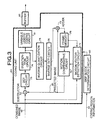
- Figure 3 is a block diagram of motion compensative moving picture coding circuit 51.
- Combined image 52 is divided into, for example, blocks of 16 ⁇ 16 pixels, each of which is coded on the basis of coding region information 53 and the coded results are stored in buffer 82.
- Skip block determination circuit 83 determines whether each block in combined image 52 is a skip block which is not to be coded. When a block is not a skip block, the block is coded by coding unit 84.
- Moving vector detection unit 71 calculates a motion vector, by comparing combined image 52 with the latest frame in frame memory 78. Then, movement compensation circuit 79 generates predicted image 80 on the basis of the motion vector. Then, subtractor 72 calculates a difference between combined image and predicted image 80. The difference is processed by DCT circuit 73, quantization circuit 74 and variable length coding circuit 81, successively, and finally the output from variable length coding circuit 81 is stored into buffer 82. Further, the output from quantization circuit 74 is processed by inverse quantization circuit 75, inverse DCT circuit 76 and adder 77, successiveively, and finally the output from adder is stored into frame memory 78.
- coding unit 84 copies in frame memory 78 the corresponding block in the latest frame. Therefore, any other circuits in coding unit 84 except frame memory 78 does not consume electric power.
- Figure 4 is a block diagram of a transmitter of TV phone using the above-explained motion compensative moving picture coding circuit.
- Voice signal from microphone 10 is coded by voice coding circuit 11, while moving picture from camera 12 and handwritten image from pen input 14 are coded by moving picture coding circuit 90 including combining circuit 50 and motion compensative moving picture coding circuit 51.
- the output from voice coding circuit 11 and moving picture coding circuit 90 are multiplexed by multiplexer 16.
- skip block determination circuit 83 determines a block to be non-coding region, that block may not be doomed to be the skip block, but may be doomed to be a block of motion vector "0".
- motion vector detection circuit 71 outputs a motion vector "0" and, afterward, other circuits in coding unit 84 work as usual.
- coding unit 84 consumes less electric power, because motion vector detection circuit 71consumes less power than usual.
- coding region information 53 may be one of threefold such as moving picture region, handwritten region without movement and handwritten region with movement.
- the moving picture region is coded conventionally, the handwritten region without movement is processed as a skip block, and the handwritten region with movement is processed as a region of motion vector "0". In this case, the power consumption becomes less than in the case of embodiment 1. Further, degradation of image quality due to a spurious motion vector can be prevented.
- coding region information 53 may be one of twofold such as moving picture region and handwritten region.
- the moving picture region is coded conventionally and the handwritten region is processed as a region of motion vector "0".
- combining circuit 50 is simplified.
- motion vector detection circuit 71 consumes less electric power, as embodiment 2. Further, degradation of image quality due to a spurious motion vector can be prevented as in embodiment 3.
Landscapes
- Engineering & Computer Science (AREA)
- Multimedia (AREA)
- Signal Processing (AREA)
- Compression Or Coding Systems Of Tv Signals (AREA)
- Two-Way Televisions, Distribution Of Moving Picture Or The Like (AREA)
- Compression, Expansion, Code Conversion, And Decoders (AREA)
Abstract
Description
Claims (8)
- A moving picture coding apparatus which comprises:a combining circuit for combining a moving picture and a handwritten image and for outputting a combined image; anda motion compensative moving picture coding circuit for coding the whole moving picture and a newly added part of said handwritten image.
- The moving picture coding apparatus according to claim 1, wherein:said combining circuit outputs, toward said motion compensative coding circuit, coding region information which indicates a region coded before the latest frame of said handwritten image is a non-coding region and said whole moving picture is a coding region; andsaid motion compensative moving picture coding circuit codes said combined image on the basis of said coding region information.
- The moving picture coding apparatus according to claim 2, wherein said coding region information identifies a region which is to be coded in said combined image and a region which is not to be coded due to an absence of difference from said latest frame.
- The moving picture coding apparatus according to claim 2, wherein said coding region information identifies a region of said moving picture, a region which is to be coded in said handwritten image and a region which is not to be coded in said handwritten image.
- The moving picture coding apparatus according to claim 2, wherein said coding region information identifies a region of said moving picture, a region of said handwritten image.
- The moving picture coding apparatus acording to claim 1 or 2, wherein said motion compensative moving picture coding circuit comprises a skip block determination circuit and a coding circuit, wherein said skip block determination circuit instructs said coding circuit to use said latest frame as data for said non-coding region.
- The moving picture coding apparatus acording to claim 1 or 2, wherein said motion compensative moving picture coding circuit comprises a skip block determination circuit and a coding circuit, wherein said skip block determination circuit instructs said coding circuit to code said non-coding region as a region with motion vector "0".
- A TV phone which comprises:voice input means for voice;voice coding means for said voice;moving picture input means for moving picture;pen input means for handwritten image;a moving picture coding apparatus which comprises: a combining circuit for combining said moving picture and said handwritten image and for outputting a combined image; and a motion compensative moving picture coding circuit for coding the whole moving picture and a newly added part of said handwritten image; anda multiplexer for multiplexing the output from said vioce coding circuit and the output from said moving picture coding apparatus.
Applications Claiming Priority (2)
| Application Number | Priority Date | Filing Date | Title |
|---|---|---|---|
| JP2000330833A JP3659161B2 (en) | 2000-10-30 | 2000-10-30 | Video encoding device and videophone terminal using the same |
| JP2000330833 | 2000-10-30 |
Publications (2)
| Publication Number | Publication Date |
|---|---|
| EP1202574A2 true EP1202574A2 (en) | 2002-05-02 |
| EP1202574A3 EP1202574A3 (en) | 2003-05-21 |
Family
ID=18807282
Family Applications (1)
| Application Number | Title | Priority Date | Filing Date |
|---|---|---|---|
| EP20010122956 Ceased EP1202574A3 (en) | 2000-10-30 | 2001-09-25 | Moving picture coding apparatus for videophone |
Country Status (4)
| Country | Link |
|---|---|
| US (2) | US6618072B2 (en) |
| EP (1) | EP1202574A3 (en) |
| JP (1) | JP3659161B2 (en) |
| CN (1) | CN1201576C (en) |
Cited By (3)
| Publication number | Priority date | Publication date | Assignee | Title |
|---|---|---|---|---|
| GB2389476A (en) * | 2002-05-16 | 2003-12-10 | Nec Corp | Mobile telephone terminal combining image and input manuscript information |
| EP1855484A3 (en) * | 2006-05-08 | 2008-08-13 | Snell and Wilcox Limited | Creation and compression of video |
| EP2763091A1 (en) * | 2013-02-01 | 2014-08-06 | LG Electronics, Inc. | Mobile terminal and control method thereof |
Families Citing this family (49)
| Publication number | Priority date | Publication date | Assignee | Title |
|---|---|---|---|---|
| US8279257B2 (en) * | 2001-03-22 | 2012-10-02 | Polycom, Inc. | High resolution graphics side channel in video conference |
| JP2003297956A (en) * | 2002-04-04 | 2003-10-17 | Toshiba Corp | Semiconductor storage device and method of manufacturing the same |
| JP2004088448A (en) * | 2002-08-27 | 2004-03-18 | Matsushita Electric Ind Co Ltd | Mobile terminal device |
| US7734144B2 (en) * | 2002-10-30 | 2010-06-08 | Koninklijke Philips Electronics N.V. | Method and apparatus for editing source video to provide video image stabilization |
| EP1590965A2 (en) * | 2003-01-29 | 2005-11-02 | Koninklijke Philips Electronics N.V. | Method of video coding for handheld apparatus |
| JP2005151073A (en) * | 2003-11-14 | 2005-06-09 | Nec Corp | Mobile terminal device with TV phone function |
| JP2006080702A (en) * | 2004-09-08 | 2006-03-23 | Nec Corp | Video telephone system, communication terminal equipment, character information transmission method used for that and its program |
| CN101496387B (en) | 2006-03-06 | 2012-09-05 | 思科技术公司 | System and method for access authentication in a mobile wireless network |
| CN101026662A (en) * | 2007-01-12 | 2007-08-29 | 华为技术有限公司 | Visual and method for writing information on it |
| CN101383939B (en) * | 2007-09-06 | 2010-09-22 | 佳世达科技股份有限公司 | Video and audio processing device for video telephone and related method thereof |
| US8355041B2 (en) | 2008-02-14 | 2013-01-15 | Cisco Technology, Inc. | Telepresence system for 360 degree video conferencing |
| US8797377B2 (en) | 2008-02-14 | 2014-08-05 | Cisco Technology, Inc. | Method and system for videoconference configuration |
| US8319819B2 (en) | 2008-03-26 | 2012-11-27 | Cisco Technology, Inc. | Virtual round-table videoconference |
| US8390667B2 (en) | 2008-04-15 | 2013-03-05 | Cisco Technology, Inc. | Pop-up PIP for people not in picture |
| CN101291436B (en) * | 2008-06-18 | 2011-02-16 | 北京中星微电子有限公司 | Video coding/decoding method and device thereof |
| US8694658B2 (en) | 2008-09-19 | 2014-04-08 | Cisco Technology, Inc. | System and method for enabling communication sessions in a network environment |
| US8477175B2 (en) | 2009-03-09 | 2013-07-02 | Cisco Technology, Inc. | System and method for providing three dimensional imaging in a network environment |
| US8659637B2 (en) | 2009-03-09 | 2014-02-25 | Cisco Technology, Inc. | System and method for providing three dimensional video conferencing in a network environment |
| US8659639B2 (en) | 2009-05-29 | 2014-02-25 | Cisco Technology, Inc. | System and method for extending communications between participants in a conferencing environment |
| US9082297B2 (en) | 2009-08-11 | 2015-07-14 | Cisco Technology, Inc. | System and method for verifying parameters in an audiovisual environment |
| US9225916B2 (en) | 2010-03-18 | 2015-12-29 | Cisco Technology, Inc. | System and method for enhancing video images in a conferencing environment |
| US9313452B2 (en) | 2010-05-17 | 2016-04-12 | Cisco Technology, Inc. | System and method for providing retracting optics in a video conferencing environment |
| US8896655B2 (en) | 2010-08-31 | 2014-11-25 | Cisco Technology, Inc. | System and method for providing depth adaptive video conferencing |
| US8599934B2 (en) | 2010-09-08 | 2013-12-03 | Cisco Technology, Inc. | System and method for skip coding during video conferencing in a network environment |
| US8599865B2 (en) | 2010-10-26 | 2013-12-03 | Cisco Technology, Inc. | System and method for provisioning flows in a mobile network environment |
| US8699457B2 (en) | 2010-11-03 | 2014-04-15 | Cisco Technology, Inc. | System and method for managing flows in a mobile network environment |
| US8730297B2 (en) | 2010-11-15 | 2014-05-20 | Cisco Technology, Inc. | System and method for providing camera functions in a video environment |
| US8902244B2 (en) | 2010-11-15 | 2014-12-02 | Cisco Technology, Inc. | System and method for providing enhanced graphics in a video environment |
| US9143725B2 (en) | 2010-11-15 | 2015-09-22 | Cisco Technology, Inc. | System and method for providing enhanced graphics in a video environment |
| US9338394B2 (en) | 2010-11-15 | 2016-05-10 | Cisco Technology, Inc. | System and method for providing enhanced audio in a video environment |
| US8542264B2 (en) | 2010-11-18 | 2013-09-24 | Cisco Technology, Inc. | System and method for managing optics in a video environment |
| US8723914B2 (en) | 2010-11-19 | 2014-05-13 | Cisco Technology, Inc. | System and method for providing enhanced video processing in a network environment |
| US9111138B2 (en) | 2010-11-30 | 2015-08-18 | Cisco Technology, Inc. | System and method for gesture interface control |
| USD678308S1 (en) | 2010-12-16 | 2013-03-19 | Cisco Technology, Inc. | Display screen with graphical user interface |
| USD678320S1 (en) | 2010-12-16 | 2013-03-19 | Cisco Technology, Inc. | Display screen with graphical user interface |
| USD682854S1 (en) | 2010-12-16 | 2013-05-21 | Cisco Technology, Inc. | Display screen for graphical user interface |
| USD682294S1 (en) | 2010-12-16 | 2013-05-14 | Cisco Technology, Inc. | Display screen with graphical user interface |
| USD678307S1 (en) | 2010-12-16 | 2013-03-19 | Cisco Technology, Inc. | Display screen with graphical user interface |
| USD682293S1 (en) | 2010-12-16 | 2013-05-14 | Cisco Technology, Inc. | Display screen with graphical user interface |
| USD682864S1 (en) | 2010-12-16 | 2013-05-21 | Cisco Technology, Inc. | Display screen with graphical user interface |
| USD678894S1 (en) | 2010-12-16 | 2013-03-26 | Cisco Technology, Inc. | Display screen with graphical user interface |
| US8692862B2 (en) | 2011-02-28 | 2014-04-08 | Cisco Technology, Inc. | System and method for selection of video data in a video conference environment |
| US8670019B2 (en) | 2011-04-28 | 2014-03-11 | Cisco Technology, Inc. | System and method for providing enhanced eye gaze in a video conferencing environment |
| US8786631B1 (en) | 2011-04-30 | 2014-07-22 | Cisco Technology, Inc. | System and method for transferring transparency information in a video environment |
| US8934026B2 (en) | 2011-05-12 | 2015-01-13 | Cisco Technology, Inc. | System and method for video coding in a dynamic environment |
| US8947493B2 (en) | 2011-11-16 | 2015-02-03 | Cisco Technology, Inc. | System and method for alerting a participant in a video conference |
| US8682087B2 (en) | 2011-12-19 | 2014-03-25 | Cisco Technology, Inc. | System and method for depth-guided image filtering in a video conference environment |
| US9681154B2 (en) | 2012-12-06 | 2017-06-13 | Patent Capital Group | System and method for depth-guided filtering in a video conference environment |
| US9843621B2 (en) | 2013-05-17 | 2017-12-12 | Cisco Technology, Inc. | Calendaring activities based on communication processing |
Family Cites Families (9)
| Publication number | Priority date | Publication date | Assignee | Title |
|---|---|---|---|---|
| JP3347336B2 (en) * | 1990-12-26 | 2002-11-20 | キヤノン株式会社 | Multimedia communication equipment |
| US5644660A (en) * | 1992-04-09 | 1997-07-01 | Picturetel Corporation | Method and apparatus for efficiently transmitting forced updates in a moving picture codec |
| JP2606583B2 (en) | 1994-05-20 | 1997-05-07 | 日本電気株式会社 | Vector image coding device |
| JP3325119B2 (en) | 1994-07-11 | 2002-09-17 | 日本電信電話株式会社 | Video phone |
| JPH0879721A (en) | 1994-09-02 | 1996-03-22 | Hitachi Ltd | Video phone |
| JP2894232B2 (en) | 1995-01-31 | 1999-05-24 | 日本電気株式会社 | Character information superimposition device |
| JPH11234639A (en) * | 1998-02-17 | 1999-08-27 | Matsushita Electric Ind Co Ltd | Videophone equipment |
| JPH11341456A (en) | 1998-05-29 | 1999-12-10 | Matsushita Graphic Communication Systems Inc | Household multimedia communication system |
| JP2000102007A (en) * | 1998-09-28 | 2000-04-07 | Matsushita Electric Ind Co Ltd | Multimedia information synthesizing device and compressed video signal generating device |
-
2000
- 2000-10-30 JP JP2000330833A patent/JP3659161B2/en not_active Expired - Lifetime
-
2001
- 2001-09-25 EP EP20010122956 patent/EP1202574A3/en not_active Ceased
- 2001-09-28 US US09/966,188 patent/US6618072B2/en not_active Expired - Lifetime
- 2001-10-30 CN CNB011377607A patent/CN1201576C/en not_active Expired - Fee Related
-
2003
- 2003-03-26 US US10/396,363 patent/US20030179285A1/en not_active Abandoned
Cited By (5)
| Publication number | Priority date | Publication date | Assignee | Title |
|---|---|---|---|---|
| GB2389476A (en) * | 2002-05-16 | 2003-12-10 | Nec Corp | Mobile telephone terminal combining image and input manuscript information |
| EP1855484A3 (en) * | 2006-05-08 | 2008-08-13 | Snell and Wilcox Limited | Creation and compression of video |
| GB2438004B (en) * | 2006-05-08 | 2011-08-24 | Snell & Wilcox Ltd | Creation and compression of video data |
| EP2763091A1 (en) * | 2013-02-01 | 2014-08-06 | LG Electronics, Inc. | Mobile terminal and control method thereof |
| US9374447B2 (en) | 2013-02-01 | 2016-06-21 | Lg Electronics Inc. | Mobile terminal and control method thereof |
Also Published As
| Publication number | Publication date |
|---|---|
| US20020051490A1 (en) | 2002-05-02 |
| JP2002142223A (en) | 2002-05-17 |
| JP3659161B2 (en) | 2005-06-15 |
| EP1202574A3 (en) | 2003-05-21 |
| US20030179285A1 (en) | 2003-09-25 |
| CN1201576C (en) | 2005-05-11 |
| CN1351446A (en) | 2002-05-29 |
| US6618072B2 (en) | 2003-09-09 |
Similar Documents
| Publication | Publication Date | Title |
|---|---|---|
| US6618072B2 (en) | Moving picture coding apparatus and TV phone using the same | |
| EP0753968B1 (en) | Moving picture transmission system and moving picture transmission apparatus | |
| US8311107B2 (en) | Image data compression device, compressing method, image data decompression device, decompressing method, and recording medium | |
| JP4755093B2 (en) | Image encoding method and image encoding apparatus | |
| EP0862331B1 (en) | Image encoding apparatus and image encoding method | |
| US7415160B2 (en) | Terminal and method for transporting still picture | |
| EP1379091A1 (en) | Video encoding and decoding apparatus and method for a communication terminal | |
| JP2573177B2 (en) | Graphic display device in electronic conference system | |
| KR20180101607A (en) | An encoding apparatus including a video switching apparatus and an encoding method including a video switching detecting method | |
| KR100414339B1 (en) | Device for encoding motion picture signals and encoding method | |
| US20190082119A1 (en) | Encoding device comprising video switching device, encoding method including video switching detection method | |
| EP1841237A1 (en) | Method and apparatus for video encoding | |
| JPH1066088A (en) | Multipoint video conference controller | |
| JPH0738722B2 (en) | Motion compensation coding method | |
| KR100397133B1 (en) | Method and System for compressing/transmiting of a picture data | |
| KR100323752B1 (en) | Method and Telephone for still picture transport | |
| JPH03250885A (en) | Video signal transmitter | |
| JP2000101983A (en) | Image transmission system | |
| JPH10145760A (en) | Image communication device | |
| JPH03250883A (en) | Video signal transmitter | |
| JPH06245204A (en) | Motion picture coder | |
| JPH03258181A (en) | Video signal transmitter | |
| JPH09116881A (en) | Video data transmission method and analog videophone | |
| JP2000165876A (en) | Image processing device | |
| JP2000209556A (en) | Image processing device and image communication device |
Legal Events
| Date | Code | Title | Description |
|---|---|---|---|
| PUAI | Public reference made under article 153(3) epc to a published international application that has entered the european phase |
Free format text: ORIGINAL CODE: 0009012 |
|
| AK | Designated contracting states |
Kind code of ref document: A2 Designated state(s): AT BE CH CY DE DK ES FI FR GB GR IE IT LI LU MC NL PT SE TR |
|
| AX | Request for extension of the european patent |
Free format text: AL;LT;LV;MK;RO;SI |
|
| PUAL | Search report despatched |
Free format text: ORIGINAL CODE: 0009013 |
|
| AK | Designated contracting states |
Designated state(s): AT BE CH CY DE DK ES FI FR GB GR IE IT LI LU MC NL PT SE TR |
|
| AX | Request for extension of the european patent |
Extension state: AL LT LV MK RO SI |
|
| 17P | Request for examination filed |
Effective date: 20030805 |
|
| AKX | Designation fees paid |
Designated state(s): DE FR GB IT |
|
| 17Q | First examination report despatched |
Effective date: 20040302 |
|
| STAA | Information on the status of an ep patent application or granted ep patent |
Free format text: STATUS: THE APPLICATION HAS BEEN REFUSED |
|
| 18R | Application refused |
Effective date: 20050616 |