EP1202438A2 - A wire-winding machine and a wire-winding method for making windings of a rotary electromechanical device - Google Patents
A wire-winding machine and a wire-winding method for making windings of a rotary electromechanical device Download PDFInfo
- Publication number
- EP1202438A2 EP1202438A2 EP01124698A EP01124698A EP1202438A2 EP 1202438 A2 EP1202438 A2 EP 1202438A2 EP 01124698 A EP01124698 A EP 01124698A EP 01124698 A EP01124698 A EP 01124698A EP 1202438 A2 EP1202438 A2 EP 1202438A2
- Authority
- EP
- European Patent Office
- Prior art keywords
- core
- wire
- magnetic pole
- core segments
- core member
- Prior art date
- Legal status (The legal status is an assumption and is not a legal conclusion. Google has not performed a legal analysis and makes no representation as to the accuracy of the status listed.)
- Granted
Links
Images




Classifications
-
- H—ELECTRICITY
- H02—GENERATION; CONVERSION OR DISTRIBUTION OF ELECTRIC POWER
- H02K—DYNAMO-ELECTRIC MACHINES
- H02K15/00—Processes or apparatus specially adapted for manufacturing, assembling, maintaining or repairing of dynamo-electric machines
- H02K15/08—Forming windings by laying conductors into or around core parts
- H02K15/095—Forming windings by laying conductors into or around core parts by laying conductors around salient poles
Definitions
- the present invention relates to a wire-winding machine and a wire-winding method for winding wires on individual magnetic pole teeth of a core member of a rotary electromechanical device, the core member being formed by joining a plurality of core segments in beltlike form by means of connectors which serve as points of bending. More particularly, the invention is concerned with a construction for achieving improved neatness of alignment of windings.
- a conventional wire-winding machine 1 of this kind disclosed in Japanese Laid-open Patent Publication No. 11-98774, for instance, is constructed such that coils 5 are formed by successively winding magnet wires 4 around individual magnetic pole teeth 3a through nozzles 1a, the magnetic pole teeth 3a projecting to the outside of a core member 3 which is joined in beltlike form by connectors and wound around drums 2a of the wire-winding machine 1, as shown in FIGS. 9 and 10.
- Another conventional wire-winding machine 6 disclosed in Japanese Laid-open Patent Publication No. 11-187630 is constructed such that magnet wires 9 which are moved along a transport guide 7 having an arc-shaped path in the direction of arrows shown in FIG. 11 are successively wound around individual magnetic pole teeth 8a through nozzles 6a, the magnetic pole teeth 8a projecting to the inside of a core member 8 which is joined in beltlike form by connectors, as illustrated in FIG. 11.
- the conventional wire-winding machines 1, 6 are intended to improve the efficiency of wire-winding operation by simultaneously winding three coils 5, 10 with the beltlike core members 3, 8 arranged in arc-shaped form, respectively.
- the magnet wires 4 are wound on the core member 3 which is arranged such that the magnetic pole teeth 3a are positioned on the outside of a bent structure with slots in the core member 3 widening outward as shown in FIG. 9, not to mention a case where the magnet wires 9 are wound on the core member 8 which is arranged such that the magnetic pole teeth 8a are positioned on the inside of a bent structure as shown in FIG. 11, however, it is difficult to make sufficient space for the wire-winding operation available.
- the present invention has been made to solve the aforementioned problems of the prior art. Accordingly, it is an object of the invention to provide a wire-winding machine and a wire-winding method which make it possible to prevent deformation of coils during the winding of magnet wires to achieve improved neatness of alignment of windings.
- the iron core is constructed of a core member which is formed by joining a plurality of core segments, each of the core segments has a yoke portion and a magnetic pole tooth which is projectingly formed on an inside surface of the yoke portion, each of the coils is formed around the magnetic pole tooth, and the core member is formed by joining both ends of the individual yoke portions by means of connectors which serve as points of bending.
- this wire-winding machine comprises a wire feeder which is constructed to wind the coils on the magnetic pole teeth as wire outlet ends of the wire feeder turn around the individual magnetic pole teeth, and a core member positioner which causes the core member to bend at the connectors in such a way that the magnetic pole teeth are positioned on the outside or inside of a bent structure, and holds the core member in positions where the core segments adjacent to each core segment which is currently a subject of wire-winding operation performed by the wire feeder do not project in the direction of its magnetic pole tooth beyond a boundary surface including the inside surface of the yoke portion of each core segment which is currently a subject of the wire-winding operation during the wire-winding operation.
- the core member positioner has a mechanism which moves the core member in such a way that the individual core segments are sequentially fed into an operating area of the wire feeder.
- This construction serves to wind the magnet wires smoothly and efficiently.
- the core member positioner has a turning device which can bend at least three successive core segments along a peripheral surface and lock them in position in such a way that their magnetic pole teeth are positioned on the outside of the bent structure.
- the core member positioner includes a plurality of chucks which can bend a specific number of the core segments arranged at specific intervals along the core member and the core segments adjacent to those core segments and lock them in position in such a way that their magnetic pole teeth are positioned on the outside of the bent structure, and a retaining device which bends and holds the multiple core segments located between the core segments locked by the chucks in such a way that the magnetic pole teeth are positioned on the inside of the bent structure, wherein the coils are formed around the core segments locked by the chucks.
- This construction also makes it possible to easily construct the core member positioner and provide a wire-winding machine capable of achieving improved neatness of alignment of windings.
- the wire feeder has fliers which guide the wires in such a way that the direction in which each of the wires is let out always matches a radial direction of the relevant magnetic pole tooth at its corresponding wire outlet end.
- This construction makes it possible to provide a wire-winding machine capable of achieving improved neatness of alignment of windings.
- the iron core is constructed of a core member which is formed by joining a plurality of core segments, each of the core segments has a yoke portion and a magnetic pole tooth which is projectingly formed on an inside surface of the yoke portion, each of the coils is formed around the magnetic pole tooth, and the core member is formed by joining both ends of the individual yoke portions by means of connectors which serve as points of bending.
- this wire-winding method comprises the steps of bending the core member in such a way that the magnetic pole teeth are positioned on the outside or inside of a bent structure, and forming the coils on one core segment while holding the core segments in positions where the core segments adjacent to the one core segment do not project in the direction of its magnetic pole tooth beyond a boundary surface including the inside surface of the yoke portion of the one core segment.
- This wire-winding method makes it possible to prevent deformation of the coils potentially caused when winding magnet wires and achieve improved neatness of alignment of windings.
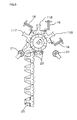
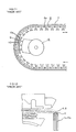
- FIG. 1 is a diagram showing the construction of a wire-winding machine according to a first embodiment of the present invention and one process of wire-winding operation performed by the wire-winding machine;
- FIG. 2 is a diagram showing a process of the wire-winding operation performed by the wire-winding machine succeeding to the process of FIG. 1;
- FIG. 3 is a diagram showing a process of the wire-winding operation performed by the wire-winding machine of FIG. 1 succeeding to the process of FIG. 2;
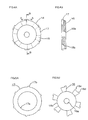
- FIGS. 4A and 4B show the construction of a rotating roller 14 of the wire-winding machine of FIG. 1, of which FIG. 4A is a front view and FIG. 4B is a sectional view showing the cross section taken along lines B-B of FIG. 4A;
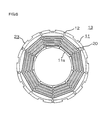
- FIGS. 4A and 4B show the construction of individual components of the rotating roller 14 of FIGS. 4A and 4B, of which FIG. 5A is a front view of a first ratchet wheel 16 and FIG. 5B is a front view of a second ratchet wheel 17; and FIG. 6 is a front view showing the construction of a stator completed by performing the wire-winding operation with the wire-winding machine of FIG. 1.
- a plurality of core segments each including a yoke portion 11c and a magnetic pole tooth 11a projecting from an inside surface 11d of the yoke portion 11c, wherein a locking groove 11b which locks on the later-described rotating roller 14 is formed at the middle of an outer surface of the yoke portion 11c.
- Designated by the numeral 12 are connecting members serving as connectors which are disposed bendably between the individual core segments 11 and join them together in beltlike form, the connecting members 12 forming a core member 13 together with the core segments 11.
- the rotating roller 14 serving as a core member positioner which is driven to intermittently turn by an unillustrated driver via a rotary shaft 15.
- the rotating roller 14 includes the first ratchet wheel 16 having a through hole 16a at a central part that is fitted on the rotary shaft 15, a boss portion 16b formed to a smaller diameter on one side, a plurality of flange portions 16c formed to a larger diameter on the opposite side at specific angular intervals, and pawls 16d individually formed projectingly to the outside of the flange portions 16c at one end in a circumferential direction, the pawls 16d being capable of fitting in the locking grooves 11b in the core segments 11, as well as the ring-shaped second ratchet wheel 17 having an through hole 17a formed at a central part that is slidably fitted on the boss portion 16b of the first ratchet wheel 16 and pawls 17b projectingly formed on
- Designated by the numeral 18 are three fliers which are mounted on wire-winding heads as unillustrated wire feeders. These fliers 18 are disposed such that they are individually positioned just beside three consecutive core segments 11 which are engaged with the rotating roller 14, and form coils 20 by winding magnet wires 19 around the individual magnetic pole teeth 11a. These fliers 18 guide the wires 19 in such a way that the direction in which each wire 19 is let out always matches a radial direction of the corresponding magnetic pole tooth 11a, or the direction of its axis, at a wire outlet end of each flier 18.
- Designated by the numeral 21 is a pair of rotatable large-diameter guide rollers which are disposed such that they individually go into contact with terminal ends of the magnetic pole teeth 11a of the core segments 11 that are located ahead and behind the three core segments 11 positioned just beside the fliers 18, and designated by the numeral 22 is a pair of rotatable small-diameter guide rollers which are disposed such that they individually go into contact with the connecting members 12 between the core segments 11 with which the two large-diameter guide rollers 21 come into contact and the adjacent core segments 11 located ahead and behind those two core segments 11.
- the pawls 16d, 17b of the rotating roller 14 fit into the locking grooves 11b of the core segment 11.1 at the forwardmost position (hereinafter referred to simply as the core segment 11.1).
- the rotating roller 14 locks with the core segment 11 at the forwardmost position as the first and second ratchet wheels 16, 17 are once relatively moved opposite to the directions of arrows A from the positions shown in FIG. 4A and, then, relatively moved in the directions of the arrows A.
- the rotating roller 14 locks anew with the core segment 11.2 second from the first one in the same manner as described above.
- the rotating roller 14 repeatedly performs the similar action.
- four core segments 11.1-11.4 including the forwardmost to the fourth ones, are locked onto the rotating roller 14.
- three core segments 11.1-11.3 including the forwardmost to the third ones, are located at positions immediately beside the three fliers 18.
- the individual core segments 11 are disposed such that their magnetic pole teeth 11a are positioned on the outside of a bent structure.
- the rotating roller 14 holds the individual core segments 11 in such positions that the core segments 11.3, 11.5 adjacent to the core segment 11.4, which is currently a subject of the wire-winding operation, would not project in the direction of its magnetic pole tooth 11a (into an area hatched in FIG. 2) beyond a boundary surface S (shown by an alternate long and short dashed line in FIG. 2) including the inside surface 11d of the yoke portion 11c. More specifically, the diameter and other parameters of the rotating roller 14 are determined in relation to the shape and dimensions of the core segments 11 so as to maintain the aforementioned positions of the core segments 11.
- the magnet wires 19 are wound around the magnetic pole teeth 11a of the three core segments 11 by operating the fliers 18 to thereby form the coils 20.
- three core segments 11.4-11.6, including the fourth to the sixth ones, are locked onto the rotating roller 14 as shown in FIG. 2 and the coils 20 are formed by the fliers 18 by reexecuting the same operation as described above.
- three core segments 11.7-11.9, including the seventh to the ninth ones, are locked onto the rotating roller 14 as shown in FIG. 3 and the coils 20 are formed by the fliers 18.
- a stator 23 is completed by fixedly joining both ends of the core member 13 by welding them together, for example.
- the coils 20 are simultaneously formed on three core segments 11, it is needless to say that productivity can be improved, and by attaching jumpers to the coils 20, it becomes possible to further improve the productivity.
- the rotating roller 14 as shown in FIG. 4 is used as the core member positioner in the above-described construction, it is needless to say that the invention is not limited thereto.
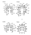
- FIGS. 7A to 7C are diagrams showing the construction of a wire-winding machine according to a second embodiment of the present invention and individual processes of wire-winding operation performed by the wire-winding machine; and FIGS. 8A to 8D are diagrams for describing the operation of a core member positioner 26 of the wire-winding machine of FIGS. 7A to 7C.
- FIG. 24 elements equivalent to those of the first embodiment are designated by the same reference numerals and a description of such elements is omitted.
- Designated by the numeral 24 are four rotatable retaining rollers serving as retaining members which are disposed with 90° angular intervals in the circumferential direction. These retaining rollers 24 are disposed such that they can move outward in radial directions by a specific distance and go into contact with connecting members 12 joining and located between those core segments 11 which are positioned where coils 20 are wound.
- Designated by the numeral 25 are three chucks which are located individually at midpoints between the adjacent retaining rollers 24, constituting the core member positioner 26 together with the retaining rollers 24. These chucks 25 move outward in radial directions by a specific distance and engage locking grooves 11b formed in those core segments 11 which are positioned where locking parts 25a formed at far ends of the chucks 25 are located, thereby locking the core segments 11 in position. Fliers 18 are positioned just beside the individual core segments 11 which are locked by these chucks 25.
- Designated by the numeral 27 are a plurality of contact members which are located on the outside of the retaining rollers 24 and the chucks 25 with specific angular intervals.
- these contact members 27 come into contact with terminal ends of magnetic pole teeth 11a of the respective core segments 11 to thereby hold a core member 13 in annular form.
- Designated by the numeral 28 are a plurality of clasping members which can grasp the magnetic pole teeth 11a of specific core segments 11 and move the core segments 11 in a circumferential direction by as much as one segment-to-segment interval while the core member 13 is held in the annular form. While the fliers 18 are winding magnet wires 19, the clasping members 28 are held at standby positions where they would not interfere with wire-winding operation together with the contact members 27.
- the individual chucks 25 move outward and their locking parts 25a fit in the locking grooves 11b of the first, fourth and seventh core segments 11.1, 11.4, 11.7 to lock them in position, as shown in FIG. 8A.
- the retaining rollers 24 at their original positions go into contact with joints between the second and third core segments 11.2, 11.3, the fifth and sixth core segments 11.5, 11.6, and between the eighth and ninth core segments 11.8, 11.9.
- the first, fourth and seventh core segments 11.1, 11.4, 11.7 and their adjacent core segments 11.2, etc. are bent such that their magnetic pole teeth 11a are individually positioned on the outside of a bent structure on a common circumference.
- the second and third core segments 11.2, 11.3, the fifth and sixth core segments 11.5, 11.6 and the eighth and ninth core segments 11.8, 11.9 are brought into positions where they are bent such that their magnetic pole teeth 11a are individually positioned on the inside of a bent structure. Then, as shown in FIG. 7A, the coils 20 are formed by winding the magnet wires 19 by the fliers 18 on the magnetic pole teeth 11a of the first, fourth and seventh core segments 11.1, 11.4, 11.7 which are locked by the individual chucks 25.
- the individual contact members 27 are set at specific positions, the locking parts 25a of the individual chucks 25 are disengaged from the locking grooves 11b of the core segments 11, and the individual retaining rollers 24 are moved outward to push the respective core segments 11.
- the terminal ends of the individual magnetic pole teeth 11a are brought into contact with the contact members 27, thereby shaping the core member 13 into the annular form.
- the magnetic pole teeth 11a of the second, fifth and eighth core segments 11.2, 11.5, 11.8 are clamped by the clasping members 28, the retaining rollers 24 are brought back to their original positions as shown in FIG.
- each core segment 11 shifts by one segment-to-segment interval and the second, fifth and eighth core segments 11.2, 11.5, 11.8 are set at positions corresponding to the individual fliers 18 instead of the first, fourth and seventh core segments 11.1, 11.4, 11.7.
- the contact members 27 which are currently in contact with the magnetic pole teeth 11a of the first, third, fourth, sixth, seventh and ninth core segments 11.1, 11.3, 11.4, 11.6, 11.7, 11.9 are moved inward so that joints between the individual core segments 11 go into contact with the retaining rollers 24, whereby the second, fifth and eighth core segments 11.2, 11.5, 11.8 and their adjacent core segments 11.1, etc. are bent such that their magnetic pole teeth 11a are individually positioned on the outside of a bent structure on the common circumference. Also, the third and fourth core segments 11.3, 11.4 and the sixth and seventh core segments 11.6, 11.7 are brought into positions where they are bent such that their magnetic pole teeth 11a are individually positioned on the inside of a bent structure. Then, as shown in FIG.
- the individual chucks 25 lock the relevant core segments 11 and the coils 20 are formed by winding the magnet wires 19 by the fliers 18 on the magnetic pole teeth 11a of the second, fifth and eighth core segments 11.2, 11.5, 11.8 in a manner similar to what is shown in FIG. 7A.
- the coils 20 are formed by winding the magnet wires 19 by the fliers 18 on the magnetic pole teeth 11a of the third, sixth and ninth core segments 11.3, 11.6, 11.9 which are locked by the individual chucks 25 as shown in FIG. 7C.
- the core member 13 is finally bent at the individual connecting members 12 to form an annular shape such that the magnetic pole teeth 11a on which the coils 20 have been formed are positioned on the inside in a fashion similar to what is shown in FIG. 6 as described with reference to the foregoing first embodiment.
- a stator is completed by fixedly joining both ends of the core member 13 by welding them together, for example.
- groups of three core segments 11 i.e., the first, fourth and seventh ones, the second, fifth and eighth ones, and the third, sixth and ninth ones) of the core member 13 are successively locked by the chucks 25 and, constrained by the chucks 25 and the retaining rollers 24, the core member 13 is bent in the above-described fashion according to the second embodiment.
- the core segments 11 adjacent to the core segment 11, which is currently the subject of the wire-winding operation do not project in the direction of its magnetic pole tooth 11a beyond the boundary surface S including the inside surface lid of the yoke portion 11c.
- the coils 20 are simultaneously formed on three core segments 11, it is needless to say that productivity can be improved, and by attaching jumpers to the coils 20, it becomes possible to further improve the productivity. Furthermore, since the coils 20 are formed on every third core segment 11, it is easier to dispose the fliers 18 from the viewpoint of space requirements for installation. Although the groups of every third core segment 11 are successively locked by the chucks 25 with 90° angular intervals in the above-described construction, it is needless to say that the invention is not limited thereto.
Landscapes
- Engineering & Computer Science (AREA)
- Manufacturing & Machinery (AREA)
- Power Engineering (AREA)
- Manufacture Of Motors, Generators (AREA)
- Iron Core Of Rotating Electric Machines (AREA)
- Windings For Motors And Generators (AREA)
- Insulation, Fastening Of Motor, Generator Windings (AREA)
Abstract
Description
Claims (6)
- A wire-winding machine for forming coils (20) on an iron core of a rotary electromechanical device, wherein the iron core is constructed of a core member (13) which is formed by joining a plurality of core segments (11), each of the core segments (11) has a yoke portion (11c) and a magnetic pole tooth (11a) which is formed projectingly on an inside surface (11d) of the yoke portion (11c), each of the coils (20) is formed around the magnetic pole tooth (lla), and the core member (13) is formed by joining both ends of the individual yoke portions (11c) by means of connectors (12) which serve as points of bending, the wire-winding machine comprising:a wire feeder (18) which is constructed to wind the coils (20) on the magnetic pole teeth (11a) as wire outlet ends of the wire feeder (18) turn around the individual magnetic pole teeth (11a); anda core member positioner (26) which causes the core member (13) to bend at the connectors (12) in such a way that the magnetic pole teeth (11a) are positioned on the outside or inside of a bent structure, and holds the core member (13) in positions where the core segments (11) adjacent to each core segment (11), which is currently a subject of wire-winding operation performed by the wire feeder (18), do not project in the direction of its magnetic pole tooth (lla) beyond a boundary surface including the inside surface (11d) of the yoke portion (11c) of each core segment (11) which is currently a subject of the wire-winding operation during the winding process.
- The machine according to claim 1,
wherein the core member positioner (26) has a mechanism which moves the core member (13) in such a way that the individual core segments (11) are sequentially fed into an operating area of the wire feeder (18). - The machine according to claim 1 or 2,
wherein the core member positioner (26) has a turning device (14) which is adapted to bend at least three successive core segments (11) along a peripheral surface and lock them in position in such a way that their magnetic pole teeth (lla) are positioned on the outside of the bent structure. - The machine according to claim 1 or 2,
wherein the core member positioner (26) includes:a plurality of chucks (25) which are adapted to bend a specific number of the core segments (11) arranged at specific intervals along the core member (13) and the core segments (11) adjacent to those core segments (11) and lock them in position in such a way that their magnetic pole teeth (11a) are positioned on the outside of the bent structure; anda retaining device (24) which is adapted to bend and hold the plurality of core segments (11) located between the core segments (11) locked by the chucks (25) in such a way that the magnetic pole teeth (lla) are positioned on the inside of the bent structure;wherein the coils (20) are formed around the core segments (11) locked by the chucks (25). - The machine according to any of claims 1 to 4,
wherein the wire feeder has fliers (18) which guide the wires (19) in such a way that the direction in which each of the wires (19) is let out always matches a radial direction of the relevant magnetic pole tooth (11a) at its corresponding wire outlet end. - A wire-winding method for forming coils (20) on an iron core of a rotary electromechanical device, wherein the iron core is constructed of a core member (13) which is formed by joining a plurality of core segments (11), each of the core segments (11) has a yoke portion (11c) and a magnetic pole tooth (11a) which is formed to project on an inside surface (11d) of the yoke portion (11c), each of the coils (20) is formed around the magnetic pole tooth (11a), and the core member (13) is formed by joining both ends of the individual yoke portions (11c) by means of connectors (12) which serve as points of bending, the wire-winding method comprising the following steps:bending the core member (13) in such a way that the magnetic pole teeth (11a) are positioned on the outside or inside of a bent structure; andforming the coils (20) on one core segment (11) while holding the core segments (11) in positions where the core segments (11) adjacent to the one core segment (11) do not project in the direction of its magnetic pole tooth (lla) beyond a boundary surface including the inside surface (lid) of the yoke portion (11c) of the respective core segment (11).
Applications Claiming Priority (2)
| Application Number | Priority Date | Filing Date | Title |
|---|---|---|---|
| JP2000331005A JP3681631B2 (en) | 2000-10-30 | 2000-10-30 | Winding machine and winding method |
| JP2000331005 | 2000-10-30 |
Publications (3)
| Publication Number | Publication Date |
|---|---|
| EP1202438A2 true EP1202438A2 (en) | 2002-05-02 |
| EP1202438A3 EP1202438A3 (en) | 2004-02-04 |
| EP1202438B1 EP1202438B1 (en) | 2009-02-18 |
Family
ID=18807422
Family Applications (1)
| Application Number | Title | Priority Date | Filing Date |
|---|---|---|---|
| EP01124698A Expired - Lifetime EP1202438B1 (en) | 2000-10-30 | 2001-10-16 | A wire-winding machine and a wire-winding method for forming coils of a rotary electromechanical device |
Country Status (7)
| Country | Link |
|---|---|
| US (1) | US6659385B2 (en) |
| EP (1) | EP1202438B1 (en) |
| JP (1) | JP3681631B2 (en) |
| KR (1) | KR100400152B1 (en) |
| CN (1) | CN1196246C (en) |
| DE (1) | DE60137672D1 (en) |
| TW (1) | TW538580B (en) |
Cited By (1)
| Publication number | Priority date | Publication date | Assignee | Title |
|---|---|---|---|---|
| WO2011010281A1 (en) * | 2009-07-22 | 2011-01-27 | Control Techniques Dynamics Limited | Electric device stator and methods for winding |
Families Citing this family (20)
| Publication number | Priority date | Publication date | Assignee | Title |
|---|---|---|---|---|
| JP3669966B2 (en) * | 2002-03-07 | 2005-07-13 | 日特エンジニアリング株式会社 | Winding method and winding device |
| US20040046476A1 (en) * | 2002-05-14 | 2004-03-11 | Raffaele Becherucci | Dynamo-electric machine component winding methods and apparatus |
| US7111380B2 (en) * | 2002-10-31 | 2006-09-26 | Emerson Electric Co. | Method for forming an annular stator assembly |
| JP4589153B2 (en) * | 2005-03-09 | 2010-12-01 | アスモ株式会社 | Winding method, stator manufacturing method, and winding machine |
| KR101154731B1 (en) | 2005-12-27 | 2012-06-08 | 두산인프라코어 주식회사 | Method for menufacturing stater of electric motor |
| CN101501959B (en) * | 2006-06-02 | 2012-05-09 | 博泽汽车部件有限公司及两合公司,乌茨堡 | Electric machine and method for producing an electric machine for a motor vehicle actuator drive |
| CN101098088B (en) * | 2006-06-26 | 2012-04-18 | 尼得科电机有限公司 | Segmented inner stator and brushless permanent magnet motor equipped with same |
| CA2758405C (en) * | 2009-04-29 | 2017-05-16 | Ernesto Malvestiti S.P.A. | Process and mold for producing ferromagnetic cores of electric motors |
| KR101124077B1 (en) * | 2010-07-21 | 2012-03-20 | 삼성전기주식회사 | Stator core and motor device including the same |
| JP5574932B2 (en) * | 2010-12-01 | 2014-08-20 | 三菱電機株式会社 | Winding machine |
| US9099897B2 (en) | 2011-09-13 | 2015-08-04 | L.H. Carbide Corporation | Method for connecting end sections of an annular laminated article and articles made therefrom |
| CN104350669B (en) * | 2012-05-28 | 2017-02-22 | 三菱电机株式会社 | Winding device, winding method and manufacturing method of armature |
| JP6261393B2 (en) * | 2014-03-12 | 2018-01-17 | 三菱電機株式会社 | Electric motor stator manufacturing apparatus and electric motor stator manufacturing method |
| DE102014218602A1 (en) * | 2014-09-16 | 2016-03-17 | Continental Automotive Gmbh | Method for winding a plurality of bobbins and segmented spindle |
| CN104539119B (en) * | 2014-12-26 | 2017-07-21 | 常州金康精工机械股份有限公司 | One kind, which is increased, horizontal singly ties up machine |
| JP6170545B2 (en) * | 2015-12-22 | 2017-07-26 | 本田技研工業株式会社 | Rotating electrical machine manufacturing apparatus and rotating electrical machine manufacturing method |
| JP6914992B2 (en) * | 2019-06-24 | 2021-08-04 | シナノケンシ株式会社 | Stator, stator manufacturing method and outer rotor type motor |
| EP4012903A1 (en) * | 2020-12-09 | 2022-06-15 | ATOP S.p.A. | Method and apparatus for producing a stator of a dynamo-electric machine |
| KR102664478B1 (en) * | 2021-10-19 | 2024-05-14 | 주식회사 야호텍 | Apparatus of winding coil with wire tension holding |
| KR102769657B1 (en) * | 2021-11-18 | 2025-02-17 | 정택명 | Apparatus for winding wire |
Family Cites Families (15)
| Publication number | Priority date | Publication date | Assignee | Title |
|---|---|---|---|---|
| US4048605A (en) * | 1976-04-05 | 1977-09-13 | Sangamo Electric Company | Split core current transformer having an interleaved joint and hinge structure |
| JPS5917851A (en) * | 1982-07-16 | 1984-01-30 | Shukichi Sakuma | Winding method of multipole core |
| JP2888142B2 (en) * | 1993-11-08 | 1999-05-10 | 三菱電機株式会社 | Rotary motor and method of manufacturing the same |
| JP3430521B2 (en) * | 1992-09-24 | 2003-07-28 | 松下電器産業株式会社 | Rotating electric machine stator |
| JPH08149771A (en) * | 1994-11-15 | 1996-06-07 | Nippondenso Co Ltd | Magnet generator stator and method of manufacturing the same |
| JP3017085B2 (en) * | 1995-11-02 | 2000-03-06 | 三菱電機株式会社 | Rotating electric machine and method of manufacturing the same |
| JP3353616B2 (en) | 1996-08-20 | 2002-12-03 | 三菱電機株式会社 | Winding method and winding device |
| JP3680482B2 (en) * | 1997-03-28 | 2005-08-10 | 松下電器産業株式会社 | Electric motor stator constituent member, electric motor stator, electric motor manufacturing method |
| TW411653B (en) * | 1997-04-11 | 2000-11-11 | Toshiba Corp | Stator for dynamoelectric machine and method of making the same |
| JPH1118331A (en) * | 1997-06-30 | 1999-01-22 | Matsushita Electric Ind Co Ltd | Motor stator |
| JP3466435B2 (en) | 1997-09-19 | 2003-11-10 | 三菱電機株式会社 | Stator manufacturing method |
| JP3354462B2 (en) | 1997-12-04 | 2002-12-09 | 三菱電機株式会社 | Winding machine |
| JP3934232B2 (en) | 1997-12-18 | 2007-06-20 | 三工機器株式会社 | Coil winding method to stator core |
| JP3279279B2 (en) * | 1998-06-30 | 2002-04-30 | 三菱電機株式会社 | Iron core equipment |
| JP2000224791A (en) * | 1999-01-27 | 2000-08-11 | Mitsubishi Electric Corp | Motor stator |
-
2000
- 2000-10-30 JP JP2000331005A patent/JP3681631B2/en not_active Expired - Lifetime
-
2001
- 2001-08-07 US US09/922,686 patent/US6659385B2/en not_active Expired - Fee Related
- 2001-09-12 TW TW090122539A patent/TW538580B/en not_active IP Right Cessation
- 2001-10-16 EP EP01124698A patent/EP1202438B1/en not_active Expired - Lifetime
- 2001-10-16 DE DE60137672T patent/DE60137672D1/en not_active Expired - Lifetime
- 2001-10-25 CN CNB01137506XA patent/CN1196246C/en not_active Expired - Lifetime
- 2001-10-29 KR KR10-2001-0066611A patent/KR100400152B1/en not_active Expired - Fee Related
Cited By (4)
| Publication number | Priority date | Publication date | Assignee | Title |
|---|---|---|---|---|
| WO2011010281A1 (en) * | 2009-07-22 | 2011-01-27 | Control Techniques Dynamics Limited | Electric device stator and methods for winding |
| CN102474138A (en) * | 2009-07-22 | 2012-05-23 | 掌控技术动力有限公司 | Electrical device stator and method for winding |
| CN102474138B (en) * | 2009-07-22 | 2015-10-14 | 掌控技术动力有限公司 | Electrical device stator and method for winding |
| US10530200B2 (en) | 2009-07-22 | 2020-01-07 | Control Techniques Dynamics Limited | Electric device stator and methods for winding |
Also Published As
| Publication number | Publication date |
|---|---|
| US20020050541A1 (en) | 2002-05-02 |
| KR20020034882A (en) | 2002-05-09 |
| US6659385B2 (en) | 2003-12-09 |
| CN1351406A (en) | 2002-05-29 |
| EP1202438B1 (en) | 2009-02-18 |
| JP2002142417A (en) | 2002-05-17 |
| CN1196246C (en) | 2005-04-06 |
| DE60137672D1 (en) | 2009-04-02 |
| EP1202438A3 (en) | 2004-02-04 |
| JP3681631B2 (en) | 2005-08-10 |
| TW538580B (en) | 2003-06-21 |
| KR100400152B1 (en) | 2003-10-01 |
Similar Documents
| Publication | Publication Date | Title |
|---|---|---|
| EP1202438B1 (en) | A wire-winding machine and a wire-winding method for forming coils of a rotary electromechanical device | |
| US5986377A (en) | Stator for dynamoelectric machine | |
| JP3285534B2 (en) | Stator of vehicle alternator | |
| US10491056B2 (en) | Stator formed by winding stator coils, rotary electric machine using said stator, method for manufacturing stator formed by winding stator coils, and method for manufacturing rotary electric machine | |
| JP2011229248A (en) | Motor | |
| EP3379704A1 (en) | Coil forming device and coil forming method | |
| JP5682800B2 (en) | Stator for rotating electric machine and method for manufacturing the same | |
| US20180198353A1 (en) | Method for manufacturing stator and method for manufacturing rotating electrical machine | |
| JP2003134751A (en) | Method of forming coil and jig used for forming coil | |
| US20160028295A1 (en) | Method of manufacturing stator for rotary electric machine | |
| US20180212498A1 (en) | Coil unit arrangement device | |
| JP6486545B2 (en) | Stator for rotating electrical machine, rotating electrical machine using the same, and method for manufacturing stator for rotating electrical machine | |
| JP3988303B2 (en) | Stator manufacturing method and manufacturing apparatus thereof | |
| JP2000014095A (en) | Tooth-shaped stator, coil assembly method and coil assembly device | |
| JP7771021B2 (en) | Stator manufacturing method and stator manufacturing device | |
| JP2003125564A (en) | Rotary electric machine coil manufacturing equipment | |
| JP5255827B2 (en) | Winding method, winding machine and holding jig for split core type work | |
| US6565032B1 (en) | Winding method and apparatus of armature | |
| JP2019126144A (en) | Wave wound coil holding device, holding method, and insertion method | |
| JP3554673B2 (en) | Method and apparatus for winding an armature | |
| JP2008172863A (en) | Rotating electric machine and manufacturing method thereof | |
| JP3554672B2 (en) | Armature winding method | |
| JP2001161048A (en) | Method of manufacturing stator for rotating electric machine | |
| JP7596958B2 (en) | Armature manufacturing apparatus and armature manufacturing method | |
| JP4474805B2 (en) | Coil twist shaping method |
Legal Events
| Date | Code | Title | Description |
|---|---|---|---|
| PUAI | Public reference made under article 153(3) epc to a published international application that has entered the european phase |
Free format text: ORIGINAL CODE: 0009012 |
|
| AK | Designated contracting states |
Kind code of ref document: A2 Designated state(s): AT BE CH CY DE DK ES FI FR GB GR IE IT LI LU MC NL PT SE TR |
|
| AX | Request for extension of the european patent |
Free format text: AL;LT;LV;MK;RO;SI |
|
| PUAL | Search report despatched |
Free format text: ORIGINAL CODE: 0009013 |
|
| AK | Designated contracting states |
Kind code of ref document: A3 Designated state(s): AT BE CH CY DE DK ES FI FR GB GR IE IT LI LU MC NL PT SE TR |
|
| AX | Request for extension of the european patent |
Extension state: AL LT LV MK RO SI |
|
| 17P | Request for examination filed |
Effective date: 20040407 |
|
| AKX | Designation fees paid |
Designated state(s): DE FR GB NL |
|
| RAP1 | Party data changed (applicant data changed or rights of an application transferred) |
Owner name: MITSUBISHI DENKI KABUSHIKI KAISHA |
|
| 17Q | First examination report despatched |
Effective date: 20080108 |
|
| GRAP | Despatch of communication of intention to grant a patent |
Free format text: ORIGINAL CODE: EPIDOSNIGR1 |
|
| GRAS | Grant fee paid |
Free format text: ORIGINAL CODE: EPIDOSNIGR3 |
|
| GRAA | (expected) grant |
Free format text: ORIGINAL CODE: 0009210 |
|
| RIN1 | Information on inventor provided before grant (corrected) |
Inventor name: OMURA, KAZUYA Inventor name: TAKAI, KEIJI Inventor name: NAKAHARA, YUJI Inventor name: KAWASUGI, NAOKI Inventor name: AKITA, HIROYUKI Inventor name: TOMITA, KAZUNARI Inventor name: MIYAKE, NOBUAKI |
|
| AK | Designated contracting states |
Kind code of ref document: B1 Designated state(s): DE FR GB NL |
|
| REG | Reference to a national code |
Ref country code: GB Ref legal event code: FG4D |
|
| REF | Corresponds to: |
Ref document number: 60137672 Country of ref document: DE Date of ref document: 20090402 Kind code of ref document: P |
|
| REG | Reference to a national code |
Ref country code: GB Ref legal event code: S27 Free format text: APPLICATION FILED; APPLICATION TO AMEND SPECIFICATION UNDER SECTION 27 FILED ON 12 MAY 2009 |
|
| REG | Reference to a national code |
Ref country code: GB Ref legal event code: S27 Free format text: APPLICATION OPEN FOR OPPOSITION |
|
| PLBE | No opposition filed within time limit |
Free format text: ORIGINAL CODE: 0009261 |
|
| STAA | Information on the status of an ep patent application or granted ep patent |
Free format text: STATUS: NO OPPOSITION FILED WITHIN TIME LIMIT |
|
| 26N | No opposition filed |
Effective date: 20091119 |
|
| REG | Reference to a national code |
Ref country code: GB Ref legal event code: S27 Free format text: SPECIFICATION AMENDED; APPLICATION FOR AMENDMENT UNDER SECTION 27 FILED ON 12 MAY 2009, ALLOWED ON 5 JANUARY 2010 |
|
| REG | Reference to a national code |
Ref country code: GB Ref legal event code: 746 Effective date: 20110513 |
|
| REG | Reference to a national code |
Ref country code: DE Ref legal event code: R084 Ref document number: 60137672 Country of ref document: DE Effective date: 20110627 Ref country code: DE Ref legal event code: R084 Ref document number: 60137672 Country of ref document: DE Effective date: 20110506 |
|
| PGFP | Annual fee paid to national office [announced via postgrant information from national office to epo] |
Ref country code: NL Payment date: 20140910 Year of fee payment: 14 |
|
| PGFP | Annual fee paid to national office [announced via postgrant information from national office to epo] |
Ref country code: FR Payment date: 20141008 Year of fee payment: 14 Ref country code: GB Payment date: 20141015 Year of fee payment: 14 Ref country code: DE Payment date: 20141007 Year of fee payment: 14 |
|
| REG | Reference to a national code |
Ref country code: DE Ref legal event code: R119 Ref document number: 60137672 Country of ref document: DE |
|
| GBPC | Gb: european patent ceased through non-payment of renewal fee |
Effective date: 20151016 |
|
| REG | Reference to a national code |
Ref country code: NL Ref legal event code: MM Effective date: 20151101 |
|
| PG25 | Lapsed in a contracting state [announced via postgrant information from national office to epo] |
Ref country code: DE Free format text: LAPSE BECAUSE OF NON-PAYMENT OF DUE FEES Effective date: 20160503 Ref country code: GB Free format text: LAPSE BECAUSE OF NON-PAYMENT OF DUE FEES Effective date: 20151016 |
|
| REG | Reference to a national code |
Ref country code: FR Ref legal event code: ST Effective date: 20160630 |
|
| PG25 | Lapsed in a contracting state [announced via postgrant information from national office to epo] |
Ref country code: FR Free format text: LAPSE BECAUSE OF NON-PAYMENT OF DUE FEES Effective date: 20151102 Ref country code: NL Free format text: LAPSE BECAUSE OF NON-PAYMENT OF DUE FEES Effective date: 20151101 |