EP1202415A1 - UPS cabinet and method of assembly - Google Patents
UPS cabinet and method of assembly Download PDFInfo
- Publication number
- EP1202415A1 EP1202415A1 EP01204065A EP01204065A EP1202415A1 EP 1202415 A1 EP1202415 A1 EP 1202415A1 EP 01204065 A EP01204065 A EP 01204065A EP 01204065 A EP01204065 A EP 01204065A EP 1202415 A1 EP1202415 A1 EP 1202415A1
- Authority
- EP
- European Patent Office
- Prior art keywords
- cabinet
- components
- magnetic components
- ups
- power
- Prior art date
- Legal status (The legal status is an assumption and is not a legal conclusion. Google has not performed a legal analysis and makes no representation as to the accuracy of the status listed.)
- Withdrawn
Links
- 238000000034 method Methods 0.000 title claims description 12
- 230000005291 magnetic effect Effects 0.000 claims abstract description 30
- 239000003990 capacitor Substances 0.000 claims abstract description 18
- 230000000712 assembly Effects 0.000 abstract description 6
- 238000000429 assembly Methods 0.000 abstract description 6
- 238000004519 manufacturing process Methods 0.000 description 4
- 230000004048 modification Effects 0.000 description 4
- 238000012986 modification Methods 0.000 description 4
- 230000001681 protective effect Effects 0.000 description 3
- 230000004075 alteration Effects 0.000 description 2
- 239000002537 cosmetic Substances 0.000 description 2
- 238000012423 maintenance Methods 0.000 description 2
- 230000004888 barrier function Effects 0.000 description 1
- 230000008901 benefit Effects 0.000 description 1
- 230000015556 catabolic process Effects 0.000 description 1
- 238000010276 construction Methods 0.000 description 1
- 238000001816 cooling Methods 0.000 description 1
- 238000006731 degradation reaction Methods 0.000 description 1
- 238000013461 design Methods 0.000 description 1
- 230000000694 effects Effects 0.000 description 1
- 238000005516 engineering process Methods 0.000 description 1
- 238000009434 installation Methods 0.000 description 1
- 239000012212 insulator Substances 0.000 description 1
- 239000011159 matrix material Substances 0.000 description 1
- 239000002184 metal Substances 0.000 description 1
- 230000008569 process Effects 0.000 description 1
- 238000012545 processing Methods 0.000 description 1
- 239000007787 solid Substances 0.000 description 1
Images



Classifications
-
- H—ELECTRICITY
- H02—GENERATION; CONVERSION OR DISTRIBUTION OF ELECTRIC POWER
- H02B—BOARDS, SUBSTATIONS OR SWITCHING ARRANGEMENTS FOR THE SUPPLY OR DISTRIBUTION OF ELECTRIC POWER
- H02B1/00—Frameworks, boards, panels, desks, casings; Details of substations or switching arrangements
- H02B1/26—Casings; Parts thereof or accessories therefor
- H02B1/30—Cabinet-type casings; Parts thereof or accessories therefor
- H02B1/32—Mounting of devices therein
Definitions
- the present invention relates generally to an uninterruptible power supply (UPS) and, more particularly to a cabinet containing an uninterruptible power supply.
- UPS uninterruptible power supply
- AC commercial power is used as a primary power source for computers and other data processing equipment that in turn use stored program and solid state technology. These circuits are generally very sensitive to input power variations from a desired standard waveform. However, commercial AC power waveforms are subject to many variations due to the demands of other users on the power line and other factors. Typical undesirable variations are over-voltage, under-voltage, voltage outages and signal transients. Undesirable variations also occur due to load conditions, as well as line conditions.
- UPS's typically include a battery backup as a secondary or reserve power source, which is activated to supply power to the load upon total failure of the commercial power or significant degradation of the primary power source.
- a power inverter is used in the UPS to convert the DC power delivered by the batteries into AC power.
- FIG. 1 shows a conventional, prior art cabinet arrangement for a UPS.
- the UPS has a cabinet 10.
- the cabinet has a plurality of bus bars 20 for connection to a load, such as a computer network (not shown).
- the magnetic components 30 for the UPS such as transformers, autotransformers and inductors, are located in a lower portion or bottom of the cabinet. Separate cabinets are frequently used to hold other magnetic components, such as input transformers and bypass inductors (not shown).
- Capacitor assemblies 40 are typically above magnetic components 30 in cabinet 10.
- Power hardware electronics and controls 50 such as inverters and rectifiers, then lie above the magnetic components and the capacitor assembly.
- the magnetic components 30 are first to be placed into the cabinet during assembly. Because magnetic components 30 are voltage specific, the installation of the magnetic components determines the voltage rating of the UPS unit. Because the electronic components are typically the same for multiple voltage configurations, it would be desirable to have a UPS cabinet in which the magnetic components could be installed as a last step of the manufacturing process.
- the present invention is directed to overcoming, or at least reducing the effects of, one or more of the problems set forth above.
- the present invention relates to a cabinet containing an uninterruptible power supply.
- An initial step includes assembling a frame defining three portions.
- a plurality of bus bars install in a first portion of the frame. The bus bars are accessible through the first portion of the cabinet.
- a capacitor assembly installs in a second portion of the frame.
- a power assembly also installs in the second portion. The power assembly is accessible through the second portion.
- a power electronic component panel mounts in the second portion.
- a control panel mounts adjacent to the power electronic components in the second portion. The control panel is accessible through the second portion.
- a plurality of magnetic components install in a third portion of the frame. The plurality of magnetic components are accessible through the third portion of the cabinet.
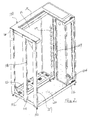
- FIG. 2 illustrates an isometric view of a frame 100 for an UPS cabinet according to the present invention.
- Components of frame 100 may be of galvanized metal and are attached by pop rivets 101. Pop-riveted construction allows the cabinet components to be shipped flat.
- Frame 100 has a base 102.
- the base has a plurality of casters 104 and stands 106.
- a plurality of posts 107 connects to the comers of base 102 and support ceiling 110.
- Ceiling 110 may have an opening 111 for locating a cooling unit or fans (not shown) in the top of frame 100.
- a dividing wall 112 also connects to base 102 and ceiling 110 of frame 100 .
- a post 108 on the side of the frame and opposing post 109 on dividing wall 112 separate the cabinet into a front portion 120 and a back portion 122.
- a bus bar portion 124 lies on the other side of dividing wall 112.
- Dividing wall 112 has a series of access or conduit openings 114 for connection of electronics in back portion 122 to the bus portion 124.
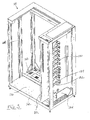
- FIG. 3 illustrates another isometric view of the UPS cabinet during the process of assembly.
- bus bars 130 are installed on dividing wall 112 on the side of bus bar portion 124.
- Bus bars 130 have a bar 132 mounted on dividing wall 112 by insulator 134.
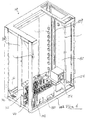
- FIG. 4 illustrates an isometric view of the UPS cabinet and frame 100 in a next step of assembly, Capacitor assemblies 140, 142 and power DC link 150 install in front portion 120 of the cabinet.
- a first capacitor assembly 140 contains a plurality of capacitors arranged in a matrix.
- First capacitor assembly 140 connects to base 102 and post 108 in front portion 120 of the cabinet.
- a second capacitor assembly 142 fits above first capacitor assembly 140 and to post 108 .
- Capacitor sub-assembly components 144 are connected as well.
- power DC Link 150 connects to base 102 near the front the cabinet. Full access to power DC Link 150 can be achieved from the front of the cabinet allowing servicing and maintenance from the front of the cabinet. Power DC Link 150 contains components, such as capacitors, necessary for connecting the UPS to the battery power supply. A control switch 154 for setting operation or service modes installs in front portion 120 for front accessibility as well.
- FIG. 5A illustrates the isometric view of the UPS cabinet in a next stage of assembly.
- Power electronic components 160 install in front portion 120.
- Power electronic components 160 such as rectifiers and inverters mount to panel 162.
- Panel 162 attaches to side post 108 and 109 and fits above capacitor assemblies 140, 142.
- a fan unit 164 may be further provided on panel 162 to cool the electronic components and draw air from the front of the cabinet.
- panel 162 has hooks 166 and 168 on one edge and additional hooks (not shown) on the opposite edge.
- the hooks allow the panel to be prefabricated and connected to the posts as shown in FIG. 5A .
- Panel 162 can be assembled independently of the frame.
- the power electronic components may be used with various voltage configurations and lends themselves well to a modular panel. Panel 162 with power electronic components 160 simply sets in the UPS cabinet during manufacture.
- connection 178 and wires 176 visible in FIG. 5B project through panel 162 and into rear portion 122 keeping high voltage connections in the back portion of the cabinet.
- FIG. 6 illustrates the isometric view of the UPS cabinet in a following step of assembly.
- a control panel 180 installs in front portion 120.
- Control panel 180 attaches to the front of the frame and connects to comer post 107 and dividing wall 112.
- the control panel may attach by hinges. No high voltage is accessible on control panel 180, so as not to expose personnel accessing the UPS from the front of the unit to high voltage connections or components.
- FIG. 7 illustrates an isometric view of the back of the UPS cabinet.
- Magnetic components 200 install in rear portion 122 of frame 100. Adding magnetic components 200 as a final step of the assembly of the cabinet allows the UPS to be configured for a specific voltage selection. Because the magnetic components determine the voltage rating of the UPS, other components of the assembly, such as the capacitor assemblies, power electronic components and control door may be mass produced independently of the cabinet. Adding the magnetic components as a final step provides the opportunity during manufacture to tailor assembly of the UPS cabinet to specific client needs or pending orders.
- Transformers stack on three tiers 210, 212 and 214 that form racks from base 102 to ceiling 210 in back portion 122.
- access to the three tiers for magnetic components 200 can be achieved from the back of the cabinet.
- magnetic components 200 can be installed last in the assembly of the UPS. Having the ability to install magnetic components 200 near the end of assembly allows the UPS to be configured for various voltage ratings.
- First tier 210 includes a rack that holds an output transformer 220.
- Second tier 212 includes a rack that holds an input autotransformer 230.
- Third tier 214 includes a rack that holds a bypass autotransformer 240.
- a series of inductor and filter racks 250, 252, 254 and 256 install in back portion 122 of frame 100. These racks also have rear accessibility.
- Rack 250 holds a plurality of input inductors 260 .
- Rack 252 holds a plurality of output inductors 270.
- Rack 254 may also hold a plurality of inductors used in an input filter, and rack 256 may hold other optional components.
- the arrangement of tiers 210-214 in rear portion 120 allows bypass transformer 240 and input transformer 230 to be included in the cabinet, which may not be available in conventional UPS cabinets.
- FIG. 8 illustrates the UPS cabinet after final assembly.
- Frame 100 of the UPS cabinet has been fitted with a cover door 300.
- Hinges 302, 304 affix door 300 to the frame.
- Hinges 302 , 304 allow door 300 to be removed during maintenance procedures. Additionally, the hinges may be used is either a left or right hand arrangement for opening the door.
- a fan unit 306 having a plurality of fans and a protective screen installs in the top of the frame.
- Protective and cosmetic panels may be added to the sides and rear of the frame.
- the left side of the UPS has a protective panel or bulkhead 310 added. Corner posts 107 and dividing post 108 are partially exposed.
- bulkhead 310 allows for attachment of another cabinet (not shown) to the frame of the UPS.
- corner posts 107 have a plurality of boltholes 312 along their length that align with boltholes in an adjacent frame of an ancillary cabinet.
- Bolts attach the ancillary cabinet to the UPS frame.
- Bulkhead 310 provides an interior barrier between the adjoined cabinets and has a wiring conduit 320 for passage of wires (not shown) between the adjoined cabinets.
Landscapes
- Engineering & Computer Science (AREA)
- Power Engineering (AREA)
- Inverter Devices (AREA)
Abstract
A cabinet for an uninterrupted power source (UPS) is disclosed. The cabinet has
three portions that characterize the frame. A front portion contains capacitor assemblies,
power DC Link, power electronic components, and a control panel. The control panel
and power DC Link are situated for front access and cover the power electronic
components and capacitors. A rear portion holds a plurality of magnetic components.
The magnetic components are accessible from the back of the cabinet and can be installed
last in the assembly of the cabinet and configured for a specific voltage rating. A bus
portion is divided from the front and rear portions and contains the bus bars for electrical
connection of the UPS.
Description
- The present invention relates generally to an uninterruptible power supply (UPS) and, more particularly to a cabinet containing an uninterruptible power supply.
- AC commercial power is used as a primary power source for computers and other data processing equipment that in turn use stored program and solid state technology. These circuits are generally very sensitive to input power variations from a desired standard waveform. However, commercial AC power waveforms are subject to many variations due to the demands of other users on the power line and other factors. Typical undesirable variations are over-voltage, under-voltage, voltage outages and signal transients. Undesirable variations also occur due to load conditions, as well as line conditions.
- Typically, UPS's include a battery backup as a secondary or reserve power source, which is activated to supply power to the load upon total failure of the commercial power or significant degradation of the primary power source. A power inverter is used in the UPS to convert the DC power delivered by the batteries into AC power.
- FIG. 1 shows a conventional, prior art cabinet arrangement for a UPS. The UPS has a
cabinet 10. The cabinet has a plurality ofbus bars 20 for connection to a load, such as a computer network (not shown). Typically, themagnetic components 30 for the UPS, such as transformers, autotransformers and inductors, are located in a lower portion or bottom of the cabinet. Separate cabinets are frequently used to hold other magnetic components, such as input transformers and bypass inductors (not shown). Capacitor assemblies 40 are typically abovemagnetic components 30 incabinet 10. Power hardware electronics andcontrols 50, such as inverters and rectifiers, then lie above the magnetic components and the capacitor assembly. - In the typical UPS cabinet, the
magnetic components 30 are first to be placed into the cabinet during assembly. Becausemagnetic components 30 are voltage specific, the installation of the magnetic components determines the voltage rating of the UPS unit. Because the electronic components are typically the same for multiple voltage configurations, it would be desirable to have a UPS cabinet in which the magnetic components could be installed as a last step of the manufacturing process. - The present invention is directed to overcoming, or at least reducing the effects of, one or more of the problems set forth above.
- In view of the foregoing and other considerations, the present invention relates to a cabinet containing an uninterruptible power supply.
- In accordance with one aspect of the present invention, there is provided a method of assembling an uninterruptible power supply. An initial step includes assembling a frame defining three portions. A plurality of bus bars install in a first portion of the frame. The bus bars are accessible through the first portion of the cabinet. A capacitor assembly installs in a second portion of the frame. A power assembly also installs in the second portion. The power assembly is accessible through the second portion. A power electronic component panel mounts in the second portion. A control panel mounts adjacent to the power electronic components in the second portion. The control panel is accessible through the second portion. A plurality of magnetic components install in a third portion of the frame. The plurality of magnetic components are accessible through the third portion of the cabinet.
- The foregoing, preferred embodiment and other aspects of the present invention will be best understood with reference to a detailed description of specific embodiments of the invention, which follows, when read in conjunction with the accompanying drawings, in which:
- FIG. 1 illustrates a conventional cabinet arrangement for an uninterruptible power supply (UPS) as evidenced in the prior art.
- FIG. 2 illustrates an isometric view of a frame for an UPS cabinet according to the present invention.
- FIG. 3 illustrates another isometric view of the UPS cabinet with the bus bars installed.
- FIG. 4 illustrates the isometric view of the UPS cabinet with the capacitor assemblies and power DC Link installed.
- FIG. 5A illustrates the isometric view of the UPS cabinet with the power electronics installed.
- FIG. 5B illustrates the isometric view of the power electronics.
- FIG. 6 illustrates the isometric view of the UPS cabinet with the control panel installed.
- FIG. 7 illustrates an isometric view of the back of the UPS cabinet with the magnetic components installed.
- FIG. 8 illustrates the UPS cabinet after final assembly.
-
- While the invention is susceptible to various modifications and alternative forms, specific embodiments have been shown by way of example in the drawings and will be described in detail herein. However, it should be understood that the invention is not intended to be limited to the particular forms disclosed. Rather, the invention is to cover all modification, equivalents and alternatives falling within the scope of the invention as defined by the appended claims.
- FIG. 2 illustrates an isometric view of a
frame 100 for an UPS cabinet according to the present invention. Components offrame 100 may be of galvanized metal and are attached bypop rivets 101. Pop-riveted construction allows the cabinet components to be shipped flat.Frame 100 has abase 102. The base has a plurality ofcasters 104 and stands 106. During assembly of the cabinet, a plurality ofposts 107 connects to the comers ofbase 102 andsupport ceiling 110.Ceiling 110 may have an opening 111 for locating a cooling unit or fans (not shown) in the top offrame 100. - A dividing
wall 112 also connects tobase 102 andceiling 110 offrame 100. Apost 108 on the side of the frame and opposingpost 109 on dividingwall 112 separate the cabinet into afront portion 120 and aback portion 122. Abus bar portion 124 lies on the other side of dividingwall 112.Dividing wall 112 has a series of access orconduit openings 114 for connection of electronics inback portion 122 to thebus portion 124. - FIG. 3 illustrates another isometric view of the UPS cabinet during the process of assembly. With
frame 100 assembled as shown in FIG. 3, bus bars 130 are installed on dividingwall 112 on the side ofbus bar portion 124. Bus bars 130 have a bar 132 mounted on dividingwall 112 byinsulator 134. - FIG. 4 illustrates an isometric view of the UPS cabinet and
frame 100 in a next step of assembly,Capacitor assemblies front portion 120 of the cabinet. Afirst capacitor assembly 140 contains a plurality of capacitors arranged in a matrix.First capacitor assembly 140 connects to base 102 and post 108 infront portion 120 of the cabinet. Asecond capacitor assembly 142 fits abovefirst capacitor assembly 140 and to post 108.Capacitor sub-assembly components 144 are connected as well. - In
front portion 120,power DC Link 150 connects to base 102 near the front the cabinet. Full access topower DC Link 150 can be achieved from the front of the cabinet allowing servicing and maintenance from the front of the cabinet.Power DC Link 150 contains components, such as capacitors, necessary for connecting the UPS to the battery power supply. Acontrol switch 154 for setting operation or service modes installs infront portion 120 for front accessibility as well. - FIG. 5A illustrates the isometric view of the UPS cabinet in a next stage of assembly. Power
electronic components 160 install infront portion 120. Powerelectronic components 160, such as rectifiers and inverters mount topanel 162.Panel 162 attaches to sidepost capacitor assemblies fan unit 164 may be further provided onpanel 162 to cool the electronic components and draw air from the front of the cabinet. - Referring to the detail of power
electronic components 160 in FIG. 5B,panel 162 hashooks Panel 162 can be assembled independently of the frame. The power electronic components may be used with various voltage configurations and lends themselves well to a modular panel.Panel 162 with powerelectronic components 160 simply sets in the UPS cabinet during manufacture. - Having power
electronic components 160 onpanel 162 offers a manufacturing advantage due to the modular design of the power electronics on the panel. Connections such asconnection 178 andwires 176 visible in FIG. 5B project throughpanel 162 and intorear portion 122 keeping high voltage connections in the back portion of the cabinet. - FIG. 6 illustrates the isometric view of the UPS cabinet in a following step of assembly. A
control panel 180 installs infront portion 120.Control panel 180 attaches to the front of the frame and connects to comerpost 107 and dividingwall 112. The control panel may attach by hinges. No high voltage is accessible oncontrol panel 180, so as not to expose personnel accessing the UPS from the front of the unit to high voltage connections or components. - FIG. 7 illustrates an isometric view of the back of the UPS cabinet.
Magnetic components 200 install inrear portion 122 offrame 100. Addingmagnetic components 200 as a final step of the assembly of the cabinet allows the UPS to be configured for a specific voltage selection. Because the magnetic components determine the voltage rating of the UPS, other components of the assembly, such as the capacitor assemblies, power electronic components and control door may be mass produced independently of the cabinet. Adding the magnetic components as a final step provides the opportunity during manufacture to tailor assembly of the UPS cabinet to specific client needs or pending orders. - Transformers stack on three
tiers base 102 toceiling 210 inback portion 122. In the present embodiment, access to the three tiers formagnetic components 200 can be achieved from the back of the cabinet. In this way,magnetic components 200 can be installed last in the assembly of the UPS. Having the ability to installmagnetic components 200 near the end of assembly allows the UPS to be configured for various voltage ratings. -
First tier 210 includes a rack that holds anoutput transformer 220.Second tier 212 includes a rack that holds aninput autotransformer 230.Third tier 214 includes a rack that holds abypass autotransformer 240. Additionally, a series of inductor and filterracks back portion 122 offrame 100. These racks also have rear accessibility.Rack 250 holds a plurality ofinput inductors 260.Rack 252 holds a plurality ofoutput inductors 270. Rack 254 may also hold a plurality of inductors used in an input filter, and rack 256 may hold other optional components. The arrangement of tiers 210-214 inrear portion 120 allowsbypass transformer 240 andinput transformer 230 to be included in the cabinet, which may not be available in conventional UPS cabinets. - FIG. 8 illustrates the UPS cabinet after final assembly.
Frame 100 of the UPS cabinet has been fitted with acover door 300.Hinges affix door 300 to the frame.Hinges door 300 to be removed during maintenance procedures. Additionally, the hinges may be used is either a left or right hand arrangement for opening the door. Afan unit 306 having a plurality of fans and a protective screen installs in the top of the frame. - Protective and cosmetic panels may be added to the sides and rear of the frame. In FIG. 8, the left side of the UPS has a protective panel or
bulkhead 310 added. Corner posts 107 and dividingpost 108 are partially exposed. Unlike a cosmetic panel that covers the entire side of the cabinet,bulkhead 310 allows for attachment of another cabinet (not shown) to the frame of the UPS. - Specifically, corner posts 107 have a plurality of
boltholes 312 along their length that align with boltholes in an adjacent frame of an ancillary cabinet. Bolts (not shown) attach the ancillary cabinet to the UPS frame.Bulkhead 310 provides an interior barrier between the adjoined cabinets and has awiring conduit 320 for passage of wires (not shown) between the adjoined cabinets. - While the invention has been described with reference to the preferred embodiments, obvious modifications and alterations are possible by those skilled in the related art. Therefore, it is intended that the invention include all such modifications and alterations to the full extent that they come within the scope of the following claims or the equivalents thereof.
Claims (14)
- A method of assembling an electronic device having both electric and magnetic components, comprising the steps of:assembling an enclosure for said electronic device;installing said electric components;determining a voltage rating;subsequent to installing said electric components, installing magnetic components corresponding to said voltage rating in. said enclosure.
- The method of claim 1 wherein said enclosure is assembled by pop-riveting.
- The method of claim 1 wherein said electric components include a capacitor assembly.
- The method of claim 1 wherein said electric components include a panel-mounted power electronics assembly attached to an interior of said enclosure by a hook.
- The method of claim 1 wherein said electric components include a control panel having no exposed high voltage on a front portion of said control panel.
- The method of claim 1 wherein said magnetic components are installed as the final step of assembling the electronic device.
- The method of claim 1 wherein said magnetic components are accessible from a rear portion of said electronic device.
- The method of claim 1 wherein said magnetic components comprise a transformer.
- A cabinet housing:wherein said magnetics are accessible from an exterior of said cabinet.a plurality of electric components attached to an interior of said cabinet;a plurality of magnetic components attached to an interior of said cabinet,
- The cabinet of claim 9 wherein said magnetics comprise at least one transformer.
- A cabinet housing an uninterruptible power supply, said cabinet having an interior divided into at least three portions including:a first portion having at least one bus bar affixed to a wall therein;a second portion having power electronic components therein;a third portion having a plurality of magnetic components disposed about said interior portion of said third portion.
- The cabinet of claim 11 wherein said power electronics include a panel attached by a hook means to said interior portion of said second portion.
- The cabinet of claim 11 wherein said power electronics include a capacitor module.
- The cabinet of claim 11 wherein said magnetic components include at least one transformer.
Applications Claiming Priority (2)
| Application Number | Priority Date | Filing Date | Title |
|---|---|---|---|
| US24399800P | 2000-10-27 | 2000-10-27 | |
| US243998P | 2000-10-27 |
Publications (1)
| Publication Number | Publication Date |
|---|---|
| EP1202415A1 true EP1202415A1 (en) | 2002-05-02 |
Family
ID=22920987
Family Applications (1)
| Application Number | Title | Priority Date | Filing Date |
|---|---|---|---|
| EP01204065A Withdrawn EP1202415A1 (en) | 2000-10-27 | 2001-10-26 | UPS cabinet and method of assembly |
Country Status (2)
| Country | Link |
|---|---|
| US (1) | US6754066B2 (en) |
| EP (1) | EP1202415A1 (en) |
Cited By (4)
| Publication number | Priority date | Publication date | Assignee | Title |
|---|---|---|---|---|
| WO2007113092A1 (en) * | 2006-03-30 | 2007-10-11 | Siemens Aktiengesellschaft | Switchgear cabinet partition |
| WO2009088755A1 (en) * | 2007-12-28 | 2009-07-16 | General Electric Company | Switchboard with ups and horizontal busbars |
| WO2012091872A1 (en) * | 2010-12-30 | 2012-07-05 | American Power Conversion Corporation | Configurable rack and related methods |
| CN104600614A (en) * | 2015-01-13 | 2015-05-06 | 盘锦广利达电气有限公司 | Skid-mounted electric control integration device |
Families Citing this family (25)
| Publication number | Priority date | Publication date | Assignee | Title |
|---|---|---|---|---|
| EP1302163B1 (en) * | 2001-10-16 | 2006-07-05 | Kabushiki Kaisha Toshiba | Apparatus for calculating an index of local blood flows |
| DE10153748A1 (en) * | 2001-10-31 | 2003-05-22 | Siemens Ag | Converter unit in modular design |
| GB2388412A (en) * | 2002-05-08 | 2003-11-12 | Emhart Llc | Blind rivet |
| US6981750B2 (en) * | 2002-09-16 | 2006-01-03 | Adc Telecommunications, Inc. | Retainer for hinged door |
| US20050180086A1 (en) * | 2004-02-12 | 2005-08-18 | Schaefer Stuart A. | Removable, portable controlable power link for controlling and powering components of structures at an agribusiness |
| US7566988B2 (en) * | 2005-06-14 | 2009-07-28 | Liebert Corporation | Method and apparatus for monitoring UPS power sources |
| US20070230094A1 (en) * | 2006-04-04 | 2007-10-04 | Carlson Curt S | Integrated, self-contained power distribution system |
| DE202006009906U1 (en) * | 2006-06-22 | 2006-10-05 | Sma Technologie Ag | Equipment retaining several individual inverter for current generating, e.g. photovoltaic installation, includes frame, to whose side elements can be releasably attached individual inveters |
| US7886983B2 (en) * | 2007-07-10 | 2011-02-15 | Liebert Corporation | Condensation prevention system and methods of use |
| US7824141B2 (en) * | 2007-08-03 | 2010-11-02 | Newfrey Llc | Blind rivet |
| US8096742B2 (en) * | 2007-08-03 | 2012-01-17 | Newfrey Llc | Blind rivet |
| US7808775B2 (en) * | 2008-03-07 | 2010-10-05 | Deere & Company | Modular power distribution system having a sealing arrangement for use in a work machine |
| US7975860B2 (en) * | 2008-04-21 | 2011-07-12 | International Business Machines Corporation | Toolless rail mounting for a computer system rack |
| US7731524B2 (en) * | 2008-04-21 | 2010-06-08 | International Business Machines Corporation | Blind docking electrical connector |
| US8446039B2 (en) * | 2009-12-11 | 2013-05-21 | Schneider Electric It Corporation | Apparatus, system and method employing a UPS |
| US8782443B2 (en) | 2010-05-25 | 2014-07-15 | Microsoft Corporation | Resource-based adaptive server loading |
| DE102010017296A1 (en) | 2010-06-08 | 2011-12-08 | Newfrey Llc | Blind rivet and mounting arrangement with a blind rivet |
| US8384244B2 (en) * | 2010-06-09 | 2013-02-26 | Microsoft Corporation | Rack-based uninterruptible power supply |
| US8487473B2 (en) | 2010-06-24 | 2013-07-16 | Microsoft Corporation | Hierarchical power smoothing |
| US8952566B2 (en) | 2010-10-26 | 2015-02-10 | Microsoft Technology Licensing, Llc | Chassis slots accepting battery modules and other module types |
| CN202663130U (en) * | 2011-12-02 | 2013-01-09 | 中兴通讯股份有限公司 | Power supply cabinet |
| CN103683845B (en) * | 2012-08-30 | 2016-04-13 | 台达电子工业股份有限公司 | Heat dissipation type power converter device |
| CN103687414B (en) * | 2012-08-30 | 2016-12-21 | 台达电子工业股份有限公司 | High-power cabinet cooling system and static var compensation system |
| JP2015050257A (en) * | 2013-08-30 | 2015-03-16 | 株式会社東芝 | Power conversion device for vehicle and railway vehicle |
| CN111422087B (en) * | 2020-04-30 | 2024-10-01 | 博众精工科技股份有限公司 | Charger and charging station |
Citations (2)
| Publication number | Priority date | Publication date | Assignee | Title |
|---|---|---|---|---|
| EP0903825A2 (en) * | 1997-09-22 | 1999-03-24 | Siemens Aktiengesellschaft | Switchgear cabinet for housing components for a series lighting circuit in an airport |
| WO1999049546A1 (en) * | 1998-03-23 | 1999-09-30 | Siemens Aktiengesellschaft | Switchgear cabinet |
Family Cites Families (4)
| Publication number | Priority date | Publication date | Assignee | Title |
|---|---|---|---|---|
| US3898537A (en) * | 1974-06-07 | 1975-08-05 | Petrolite Corp | Modular high voltage DC power supply with a removable component rack |
| US5185705A (en) * | 1988-03-31 | 1993-02-09 | Square D Company | Circuit breaker having serial data communications |
| US5025545A (en) * | 1988-07-21 | 1991-06-25 | Haas Cabinet Co., Inc. | Method of attaching and adjusting a cabinet drawer guide assembly |
| US5184280A (en) * | 1991-10-31 | 1993-02-02 | At&T Bell Laboratories | Power rectifier with flexible stacked sheave bus bar for high current carrying connections |
-
2001
- 2001-10-25 US US10/055,818 patent/US6754066B2/en not_active Expired - Lifetime
- 2001-10-26 EP EP01204065A patent/EP1202415A1/en not_active Withdrawn
Patent Citations (2)
| Publication number | Priority date | Publication date | Assignee | Title |
|---|---|---|---|---|
| EP0903825A2 (en) * | 1997-09-22 | 1999-03-24 | Siemens Aktiengesellschaft | Switchgear cabinet for housing components for a series lighting circuit in an airport |
| WO1999049546A1 (en) * | 1998-03-23 | 1999-09-30 | Siemens Aktiengesellschaft | Switchgear cabinet |
Cited By (8)
| Publication number | Priority date | Publication date | Assignee | Title |
|---|---|---|---|---|
| WO2007113092A1 (en) * | 2006-03-30 | 2007-10-11 | Siemens Aktiengesellschaft | Switchgear cabinet partition |
| RU2394323C1 (en) * | 2006-03-30 | 2010-07-10 | Сименс Акциенгезелльшафт | Partition for distribution cabinet |
| WO2009088755A1 (en) * | 2007-12-28 | 2009-07-16 | General Electric Company | Switchboard with ups and horizontal busbars |
| US8363389B2 (en) | 2007-12-28 | 2013-01-29 | General Electric Company | Switchboard with UPS and horizontal busbars |
| WO2012091872A1 (en) * | 2010-12-30 | 2012-07-05 | American Power Conversion Corporation | Configurable rack and related methods |
| US9072191B2 (en) | 2010-12-30 | 2015-06-30 | Schneider Electric It Corporation | Configurable rack and related methods |
| CN104600614A (en) * | 2015-01-13 | 2015-05-06 | 盘锦广利达电气有限公司 | Skid-mounted electric control integration device |
| CN104600614B (en) * | 2015-01-13 | 2016-04-06 | 盘锦广利达电气有限公司 | Sledge fills automatically controlled integrated apparatus |
Also Published As
| Publication number | Publication date |
|---|---|
| US20030011969A1 (en) | 2003-01-16 |
| US6754066B2 (en) | 2004-06-22 |
Similar Documents
| Publication | Publication Date | Title |
|---|---|---|
| US6754066B2 (en) | UPS cabinet and method of assembly | |
| US4691274A (en) | Modular electronic power supply | |
| US8854824B2 (en) | Modular UPS | |
| US6229691B1 (en) | Apparatus and method for mounting a power distribution unit within an equipment enclosure | |
| US7719835B1 (en) | Wiring distribution device for an electronics rack | |
| US6881898B2 (en) | Remote distribution cabinet | |
| EP2298051B1 (en) | Rack mounted cooling unit | |
| US20040032722A1 (en) | Electronics module | |
| EP1202414A2 (en) | Ancillary cabinet system for an uninterruptible power supply | |
| US6617708B2 (en) | Modular power distribution system | |
| US6999305B1 (en) | Modular electrical distribution system | |
| US20010026436A1 (en) | Apparatus and method for mounting a power distribution unit within an equipment enclosure | |
| US8378530B1 (en) | Power distribution system with rack power distribution unit | |
| CN102904426B (en) | Integration filter unit and four-quadrant frequency converter | |
| US7397653B2 (en) | Inverter design | |
| US20250311169A1 (en) | Airflow management system for power module | |
| US5132872A (en) | Low profile mounting assembly and cabinet enclosures for rack relay mounted rectifiers | |
| CN213485439U (en) | Automation equipment cabinet | |
| CN223978471U (en) | An AC-DC module supporting RJ45 quad-channel. | |
| CN223124098U (en) | Container | |
| CN223744199U (en) | Energy storage direct current side conflux cabinet | |
| CN223625415U (en) | An embedded power quality management cabinet | |
| EP4539622A1 (en) | Equipment rack arrangements and methods of installing equipment racks | |
| CN121791393A (en) | Electrical device and energy storage apparatus | |
| WO2026025567A1 (en) | Combiner cabinet body structure, combiner cabinet, and energy storage container |
Legal Events
| Date | Code | Title | Description |
|---|---|---|---|
| PUAI | Public reference made under article 153(3) epc to a published international application that has entered the european phase |
Free format text: ORIGINAL CODE: 0009012 |
|
| AK | Designated contracting states |
Kind code of ref document: A1 Designated state(s): AT BE CH CY DE DK ES FI FR GB GR IE IT LI LU MC NL PT SE TR |
|
| AX | Request for extension of the european patent |
Free format text: AL;LT;LV;MK;RO;SI |
|
| 17P | Request for examination filed |
Effective date: 20020819 |
|
| AKX | Designation fees paid |
Free format text: AT BE CH CY DE DK ES FI FR GB GR IE IT LI LU MC NL PT SE TR |
|
| STAA | Information on the status of an ep patent application or granted ep patent |
Free format text: STATUS: THE APPLICATION HAS BEEN WITHDRAWN |
|
| 18W | Application withdrawn |
Effective date: 20031007 |