EP1202307A2 - Switch and connector assembly - Google Patents
Switch and connector assembly Download PDFInfo
- Publication number
- EP1202307A2 EP1202307A2 EP01308705A EP01308705A EP1202307A2 EP 1202307 A2 EP1202307 A2 EP 1202307A2 EP 01308705 A EP01308705 A EP 01308705A EP 01308705 A EP01308705 A EP 01308705A EP 1202307 A2 EP1202307 A2 EP 1202307A2
- Authority
- EP
- European Patent Office
- Prior art keywords
- electrical
- electrical connector
- housing
- members
- contacts
- Prior art date
- Legal status (The legal status is an assumption and is not a legal conclusion. Google has not performed a legal analysis and makes no representation as to the accuracy of the status listed.)
- Withdrawn
Links
Images


Classifications
-
- H—ELECTRICITY
- H01—ELECTRIC ELEMENTS
- H01H—ELECTRIC SWITCHES; RELAYS; SELECTORS; EMERGENCY PROTECTIVE DEVICES
- H01H11/00—Apparatus or processes specially adapted for the manufacture of electric switches
- H01H11/0006—Apparatus or processes specially adapted for the manufacture of electric switches for converting electric switches
- H01H11/0031—Apparatus or processes specially adapted for the manufacture of electric switches for converting electric switches for allowing different types or orientation of connections to contacts
-
- H—ELECTRICITY
- H01—ELECTRIC ELEMENTS
- H01R—ELECTRICALLY-CONDUCTIVE CONNECTIONS; STRUCTURAL ASSOCIATIONS OF A PLURALITY OF MUTUALLY-INSULATED ELECTRICAL CONNECTING ELEMENTS; COUPLING DEVICES; CURRENT COLLECTORS
- H01R43/00—Apparatus or processes specially adapted for manufacturing, assembling, maintaining, or repairing of line connectors or current collectors or for joining electric conductors
-
- H—ELECTRICITY
- H01—ELECTRIC ELEMENTS
- H01R—ELECTRICALLY-CONDUCTIVE CONNECTIONS; STRUCTURAL ASSOCIATIONS OF A PLURALITY OF MUTUALLY-INSULATED ELECTRICAL CONNECTING ELEMENTS; COUPLING DEVICES; CURRENT COLLECTORS
- H01R4/00—Electrically-conductive connections between two or more conductive members in direct contact, i.e. touching one another; Means for effecting or maintaining such contact; Electrically-conductive connections having two or more spaced connecting locations for conductors and using contact members penetrating insulation
- H01R4/24—Connections using contact members penetrating or cutting insulation or cable strands
- H01R4/2416—Connections using contact members penetrating or cutting insulation or cable strands the contact members having insulation-cutting edges, e.g. of tuning fork type
- H01R4/2445—Connections using contact members penetrating or cutting insulation or cable strands the contact members having insulation-cutting edges, e.g. of tuning fork type the contact members having additional means acting on the insulation or the wire, e.g. additional insulation penetrating means, strain relief means or wire cutting knives
- H01R4/245—Connections using contact members penetrating or cutting insulation or cable strands the contact members having insulation-cutting edges, e.g. of tuning fork type the contact members having additional means acting on the insulation or the wire, e.g. additional insulation penetrating means, strain relief means or wire cutting knives the additional means having two or more slotted flat portions
- H01R4/2454—Connections using contact members penetrating or cutting insulation or cable strands the contact members having insulation-cutting edges, e.g. of tuning fork type the contact members having additional means acting on the insulation or the wire, e.g. additional insulation penetrating means, strain relief means or wire cutting knives the additional means having two or more slotted flat portions forming a U-shape with slotted branches
-
- H—ELECTRICITY
- H01—ELECTRIC ELEMENTS
- H01R—ELECTRICALLY-CONDUCTIVE CONNECTIONS; STRUCTURAL ASSOCIATIONS OF A PLURALITY OF MUTUALLY-INSULATED ELECTRICAL CONNECTING ELEMENTS; COUPLING DEVICES; CURRENT COLLECTORS
- H01R9/00—Structural associations of a plurality of mutually-insulated electrical connecting elements, e.g. terminal strips or terminal blocks; Terminals or binding posts mounted upon a base or in a case; Bases therefor
- H01R9/22—Bases, e.g. strip, block, panel
- H01R9/24—Terminal blocks
- H01R9/2425—Structural association with built-in components
- H01R9/2433—Structural association with built-in components with built-in switch
-
- H—ELECTRICITY
- H01—ELECTRIC ELEMENTS
- H01H—ELECTRIC SWITCHES; RELAYS; SELECTORS; EMERGENCY PROTECTIVE DEVICES
- H01H1/00—Contacts
- H01H1/58—Electric connections to or between contacts; Terminals
- H01H1/5844—Electric connections to or between contacts; Terminals making use of wire-gripping clips or springs
- H01H1/585—Electric connections to or between contacts; Terminals making use of wire-gripping clips or springs and piercing the wire insulation
-
- H—ELECTRICITY
- H01—ELECTRIC ELEMENTS
- H01H—ELECTRIC SWITCHES; RELAYS; SELECTORS; EMERGENCY PROTECTIVE DEVICES
- H01H1/00—Contacts
- H01H1/58—Electric connections to or between contacts; Terminals
- H01H1/5866—Electric connections to or between contacts; Terminals characterised by the use of a plug and socket connector
Definitions
- the present invention relates generally to electrical switch mechanisms and electrical connector components, and more particularly to a new and improved low-profile combination electrical switch and connector assembly which facilitates easy assembly of the switch mechanism and connector component, wherein the connector component and switch mechanism are connected together in a properly oriented or polarized manner, and wherein the electrical contacts disposed within the electrical connector not only facilitate easy connection to external wires through means of insulation displacement techniques, but in addition, the electrical contacts are self-supporting and self-generate requisite forces for electrical connection to tab members of the switch mechanism.
- Switch mechanisms and operatively associated electrical connector components are often mounted upon support panels, walls, or the like so as to remotely control electrical appliances, lighting fixtures, or other electrical equipment. Space for accommodating the electrical switch mechanisms and their operatively associated electrical connector components, however, is often limited, confined, or simply not readily accessible whereby it becomes necessary to minimize or optimize the component or hardware dimensions.
- the electrical switch mechanism and the electrical connector component be able to be electrically connected to, and when required, electrically disconnected from, each other in a relatively simple, properly oriented, and cost-effective manner, preferably by means of non-soldered plug-in and/or insulation displacement type connections. Accordingly, replacement or exchange of the assembly components would be facilitated and expedited.
- such an electrical connector and switch mechanism assembly does not presently exist in the current state of the art.
- a combination electrical switch mechanism and electrical connector assembly which comprises an electrical connector having electrical contacts disposed therein, and a switch mechanism which includes a plurality of dependent tab members for insertion within the electrical connector for mating with the contact members of the electrical connector in a frictionfit solderless manner.
- the switch mechanism also comprises a three-sided shrouded housing whereby the switch mechanism can only be mated with the electrical connector in a predetermined polarized manner.
- the contact members of the electrical connector also have insulation displacement portions for terminating external wiring therein in a solderless manner, and the contact members are self-supporting so as not to require external support from the electrical connector housing.
- the contact members also self-generate the requisite forces required for mating with the dependent tab members of the switch mechanism.
- a first embodiment of the combination electrical switch mechanism and electrical connector assembly is disclosed, is generally indicated by the reference character 10, and is seen to comprise the electrical switch mechanism 12 and the electrical connector 14.
- the switch mechanism 12 may comprise, for example, a conventional rocker switch element 16 which is mounted within a switch plate 18 wherein the plate 18 is adapted to be disposed externally upon a support panel, wall, plate, or the like, not shown, when the switch mechanism 12 is mounted upon the support panel, wall, plate, or the like, not shown.
- the switch mechanism 12 further comprises a housing 20 which has a configuration which is substantially that of a rectangular parallelepiped, and a pair of flexible mounting fingers 22 is mounted upon respective opposite ends 24 of the switch housing 20 in a cantilevered manner.
- Each one of the flexible mounting fingers 22 is integrally mounted at its lower end portion upon a lower end region of the switch housing 20, while an upper distal end portion 26 of each finger 22 is disposed at an elevational level which is below the lower edge of switch plate 18 so as to define a space 28 having a predetermined dimension.
- the dimension of space 28 is adapted to substantially match the thickness dimension of the support panel, wall, plate, or the like, not shown, upon which the combination switch mechanism and electrical connector 10 is to be mounted in a snap-fitted manner.
- the switch mechanism 12 is adapted to be inserted downwardly through an aperture, not shown, defined within the support panel, plate, wall, or the like, also not shown, whereby the flexible fingers 22 will be forced inwardly, from their illustrated positions toward the switch mechanism housing 20, by the side walls of the support panel, plate, wall, or the like, not shown, which define the aperture, not shown.
- the fingers 22 will expand outwardly or snap back to their illustrated positions so as to lockingly engage the undersurface of the support panel, plate, wall, or the like, whereby the switch mechanism 12 will be fixedly mounted upon the support panel, wall, plate, or the like, not shown.
- the switch mechanism 12 is seen to further comprise a plurality of dependent blade-type contact members 30 extending downwardly from the bottom portion of the switch housing 20, and a three-sided shroud 32 integral with the end walls 24 of the switch housing, and the rear wall, not shown, of the switch housing 20, and depending downwardly so as to surround the dependent blade members 30 upon three sides thereof, leaving the fourth front side open, and also define a substantially enclosed space 34.
- the electrical connector 14 is seen to comprise an electrical connector contact housing 36 which has the configuration of a rectangular parallelepiped and which is supported upon a lower base or foundation 38.
- the upper surface 40 of the electrical connector housing 36 is seen to comprise a plurality of apertures 42 for receiving or accommodating insertion or reception of the dependent blade members 30 of the switch mechanism 12, and the apertures 42 connect to interior hollow portions of the housing 36 within which electrical contact portions are disposed, as will be more fully disclosed and explained hereinafter, for mating electrical connection with the blade members 30 of the switch mechanism 12 when the switch mechanism 12 and electrical connector 14 are mated together as a result of the switch mechanism 12 being moved downwardly relative to the electrical connector J4 in accordance with the arrow D or as a result of the electrical connector 14 being moved upwardly relative to the switch mechanism 12 in accordance with the arrow U.
- Opposite end walls 44 of the dependent shroud are provided with apertures 46, and opposite end walls 48 of the connector housing 36 are provided with detents 50 which are adapted to be lockingly snap-fitted within the apertures 46 of the shroud end walls 44 when the switch mechanism 12 is mated with the electrical connector 14.
- the switch housing 20 when the electrical switch mechanism 12 is mounted upon or mated with the electrical connector 14, the switch housing 20 is disposed atop the connector housing 36 and the three-sided shroud 32 of the switch mechanism 12 substantially encloses the opposite end walls 48,48 and rear wall, not shown, of the electrical connector housing 36.
- the bottom surface portions of the shroud end walls 44,44, as well as the bottom portion of its rear wall 52, are supported upon the base or foundation 38 of the connector 14.
- the electrical connector 14 is also provided with an auxiliary housing portion 53 which is integrally formed upon and projects forwardly of the connector housing 36.Auxiliary housing portion 53 is provided f or facilitating insertion of the electrical connector contacts into the electrical connector 14 wherein the electrical connector contacts provide electrical connection between external wiring and the contact blade members 30 of the switch mechanism 12.
- the switch mechanism 12 due to the interactive structure of the switch mechanism 12 and the electrical connector 14, and in particular, the provision of the three-sided shroud portion 32 upon the switch mechanism 12 as well as the provision of the auxiliary housing portion 53 upon the electrical connector 14, the switch mechanism 12 must be disposed in a uniquely required orientation when the switch mechanism 12 is to be mounted upon the electrical connector 14 whereby, in effect, a polarized connection is established or defined between the switch mechanism 12 and the electrical connector 14 so as to ensure proper mounting or mating of such components parts with respect to each other.
- the electrical connector 14 is adapted to have inserted therein three electrical connector contacts for electrical mating with the three dependent blade members 30 of the switch mechanism. Accordingly, with additional reference being made to FIGURES 3 and 4, the new and improved electrical connector contacts are disclosed and are generally indicated by the reference character 54. It is noted that FIGURE 3 discloses the electrical contact 54 as disposed in its normal orientation for insertion within the electrical connector 14, while FIGURE 4 discloses the electrical contact 54 as disposed in an inverted mode so as to clearly illustrate additional features of the contact 54 which are not apparent from FIGURE 3.
- orientation terminology will be used in connection with the description of the contact 54 as shown in FIGURE 3, although such terminology may not be accurate with respect to the disclosure of FIGURE 4 due to the inversion of the contact 54 as disclosed in FIGURE 4 as compared to its orientation in FIGURE 3, however, the component parts of the contact 54 as shown in FIGURE 4 which correspond to the same parts of the contact 54 as shown in FIGURE 3 will be designated by the same reference characters for clarity and consistency.
- each one of the electrical connector contacts 54 is seen to comprise, as considered from the viewpoint of the disposition of the contact 54 when the same is mounted within the electrical connector 14, a forwardly disposed insulation displacement contact portion 56 for electrical connection to external wiring and a rearwardly disposed blade-engaging contact portion 58 for electrical connection to the blade members 30 of the switch mechanism 12.
- the insulation displacement contact portion 56 is seen to comprise a pair of vertically spaced upper and lower insulation displacement contact members 60,62.
- the contact members 60,62 are connected to each other at left side or edge portions thereof, again as considered from the viewpoint of the disposition of the contacts 54 when the contacts 54 are disposed or mounted within the electrical connector 14, by means of a vertically disposed wall member 64, and the right side portions of the contact members 60,62 define free edge portions 66,68.
- the upstanding wall member 64 and the free edge portions 66,68 of the contacts 54 help serve to support the contacts 54 within the electrical connector 14.
- substantially central portions of the contact members 60,62 are of course provided with slotted regions 70,72 which are provided for achieving insulation displacement or insulation stripping procedures in connection with external wires, not shown, to be electrically connected to the electrical connector contacts 54 in accordance with well-known techniques.
- the blade-engaging contact portion 58 of each one of the electrical contacts 54 is seen to comprise a left side wall member 74 which, in effect, is an integral extension of the upstanding side wall member 64 of the insulation displacement contact portion 56, and a floor member 76 which is integrally connected at its left edge portion to the lower end of the upstanding wall member 74.
- a first downwardly extending blade-engaging contact member 78 is integrally connected to the upper end of the upstanding wall member 74, and a second upwardly extending blade-engaging contact member 80 is integrally connected to the right edge portion of the floor member 76.
- first blade-engaging contact member 78 is provided with a vertically central, longitudinally extending planar portion 82
- second blade-engaging contact member 80 is similarly provided with a vertically central, longitudinally extending planar portion 84 which is transversely spaced from the planar portion 82 of contact member 78 so as to permit insertion of a respective one of the blade members 30 of the switch mechanism 12 therebetween.
- planar surfaces or portions 82,84 establish surface-to-surface contact with the blade member 30, and in order to facilitate insertion of the blade member 30 into the space or channel 86 defined between the planar portions 82,84, the upper end of the contact member 78 is provided with an outwardly inclined or divergent entrance portion 88 and the upper end of the contact member 80 is similarly provided with an outwardly inclined or divergent entrance portion 90.
- both of the blade engaging contact members 78,80 are respectively freely mounted upon the upstanding wall and floor members 74,76 so as to be resiliently flexible, and in this manner, the contact members 78,80 are self-supporting self-generate the necessary forces in the transverse or lateral direction so as to properly engage a respective one of the blade members 30 when the blade member 30 is inserted into space or channel 86 between the contact portions 82,84.
- the forward end portions 92,94 of the contact members 78,80 are longitudinally or axially spaced as at 96 from rear edge portions 98,100 of the insulation displacement contact members 60,62.
- rear end portions 102,104 of the contact members 78, 80 are longitudinally or axially recessed forwardly as at 106, 108 from the respective rear edge surface portions 110,112 of the upstanding wall and horizontal floor members 74, 76 such that when the electrical contacts 54 are mounted within the electrical connector 14, the rear end portions 102,104 of the contact members 78,80 will not engage or abrade the rear internal wall surface of the electrical connector housing 36. It is also to be appreciated that all electrical connections characteristic of the combination electrical switch and connector assembly 10 of the present invention, that is, between the external wires, not shown, and the insulation displacement contacts 60,62, and between the blade members 30 and the contact members 78,80 are entirely solderless.
- the electrical connector 14, comprising the primary connector housing 36 and the auxiliary connector housing 53 comprises, for example, four upstanding wall members 114 so as to define, in effect, three electrical contact sockets 116 therebetween which extend substantially the full depth of the electrical connector 14 and within which the electrical contacts 54 will be disposed. More particularly, a horizontally disposed or extending channel 118 is defined within a vertically central portion of each left-side interior wall surface of each upstanding wall member 114, and in a similar manner, a pair of vertically spaced horizontally extending channels 120,122 are defined within vertically central portions of each right-side interior wall surface of each upstanding wall member 114.
- electrical contact vertical wall member 64/74 will be disposed within the electrical connector channel 118 while the free edge portions 66,68 of each contact 54 will be respectively disposed within the channels 120,122 of the connector 14.
- each one of the sockets 116 is also provided with an internal upstanding boss or the like, not shown, upon which the floor member 76 of each contact 54 is supported so as to support the rearward portion of each contact 54, particularly in connection with the resistance to any downward force which may be impressed thereon when the blade members 30 of the switch mechanism 12 are being inserted into the spaces 86 of the contact members 54 so as to be electrically engaged with the flexibly movable contact portions 78,80.
- each one of the upstanding wall members 114 has integrally formed upon forward end portions thereof, at upper and lower vertically spaced levels, a plurality of oppositely disposed tab members 126 which serve to retain the external wires, not shown, which are to be inserted into the sockets 116 for electrical connection to the insulation displacement contact members 60,62.
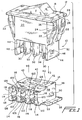
- FIGURES 5a,5b, and 6 a second embodiment of the new and improved combination electrical switch mechanism and electrical connector assembly is disclosed and is generally indicated by the reference character 210.
- the second embodiment of the combination electrical switch mechanism and electrical connector assembly 210 as disclosed within FIGURES 5a,5b and 6 is structurally and operationally similar to the first embodiment of the combination electrical switch mechanism and electrical connector assembly 10 as disclosed within FIGURES 1 and 2, except as will be specifically noted hereinafter, and accordingly component parts of the second embodiment of the combination electrical switch mechanism and electrical connector assembly 210 as disclosed within FIGURES 5a,5b and 6 which are similar to corresponding parts of the first embodiment of the combination electrical switch mechanism and electrical connector assembly 10 as disclosed within FIGURES 1 and 2 will be designated by corresponding reference characters except that the reference characters will be within the 200 and 300 series.
- the major difference between the first embodiment of the combination electrical switch mechanism and electrical connector assembly 10 as disclosed within FIGURES 1 and 2 and the second embodiment of the combination electrical switch mechanism and electrical connector assembly 210 as disclosed within FIGURES 5a,5b and 6 resides in the fact that, in lieu of the auxiliary housing portion 53 projecting forwardly from a side portion of the electrical connector housing 36 as was the case with the first embodiment of the combination electrical switch mechanism and electrical connector assembly 10 as disclosed within FIGURES 1 and 2, the auxiliary housing portion 253 of the electrical connector 214 projects downwardly from the bottom, base, or foundation portion 238 of the electrical connector housing 236.
- the contact housing 236 is disposed atop the auxiliary housing portion 253 as opposed to the housings being disposed in effect in a side-by-side arrangement as was the case of housing 36 and auxiliary housing 53 of the first embodiment of the combination electrical switch mechanism and electrical connector assembly 10 as disclosed within FIGURES 1 and 2.
- the wires to be mated with the electrical contacts disposed within the auxiliary housing portion 253 will extend horizontally, as opposed Co vertically, thus permitting the second embodiment of the combination electrical switch mechanism and electrical connector assembly 210 disclosed within FIGURES 5a,5b and 6 to be used within applications which may require orientations which are different from those afforded by the first embodiment of the combination electrical switch mechanism and electrical connector assembly 10 as disclosed within FIGURES 1 and 2.
- the auxiliary housing portion 253 comprises four upstanding wall members 314 which are disposed parallel to each other in a manner similar to the disposition of the upstanding wall members 114 of the auxiliary housing portion 53 of the first embodiment of the combination electrical switch mechanism and electrical connector assembly 10 as disclosed within FIGURES 1 and 2, however, in lieu of the horizontally disposed channels 118,120,122 extending rearwardly from forwardly disposed faces of the upstanding wall members 114, the upstanding wall members 314 are respectively provided with vertically disposed channels 318,320,322 which extend upwardly from lower or bottom surfaces 315 of the upstanding wall members 314 as best seen in FIGURE 5b.
- a new and improved combination electrical switch mechanism and electrical connector assembly has been developed wherein the assembly has a relatively low profile and wherein all electrical connections between the switch mechanism and the electrical connector, as well as between the electrical connector and external wiring, is achieved through means of solderless connections.
- the connection between the switch mechanism and the electrical connector is polarized such that the components can only be connected to each other in a predetermined proper mode or orientation.
- the electrical contacts disposed within the electrical connector are self-supporting and self-generate the necessary forces for properly mating with the blade members of the switch mechanism.
Landscapes
- Engineering & Computer Science (AREA)
- Manufacturing & Machinery (AREA)
- Details Of Connecting Devices For Male And Female Coupling (AREA)
- Switch Cases, Indication, And Locking (AREA)
- Connector Housings Or Holding Contact Members (AREA)
- Coupling Device And Connection With Printed Circuit (AREA)
- Connecting Device With Holders (AREA)
Abstract
Description
- The present invention relates generally to electrical switch mechanisms and electrical connector components, and more particularly to a new and improved low-profile combination electrical switch and connector assembly which facilitates easy assembly of the switch mechanism and connector component, wherein the connector component and switch mechanism are connected together in a properly oriented or polarized manner, and wherein the electrical contacts disposed within the electrical connector not only facilitate easy connection to external wires through means of insulation displacement techniques, but in addition, the electrical contacts are self-supporting and self-generate requisite forces for electrical connection to tab members of the switch mechanism.
- Switch mechanisms and operatively associated electrical connector components are often mounted upon support panels, walls, or the like so as to remotely control electrical appliances, lighting fixtures, or other electrical equipment. Space for accommodating the electrical switch mechanisms and their operatively associated electrical connector components, however, is often limited, confined, or simply not readily accessible whereby it becomes necessary to minimize or optimize the component or hardware dimensions. In addition, it is desirable that the electrical switch mechanism and the electrical connector component be able to be electrically connected to, and when required, electrically disconnected from, each other in a relatively simple, properly oriented, and cost-effective manner, preferably by means of non-soldered plug-in and/or insulation displacement type connections. Accordingly, replacement or exchange of the assembly components would be facilitated and expedited. Unfortunately, such an electrical connector and switch mechanism assembly does not presently exist in the current state of the art.
- A need therefore exists in the art for a new and improved combination electrical switch mechanism and electrical connector assembly wherein the electrical switch mechanism and the electrical connector has a compact profile enabling the same to be mounted within confined or restricted spatial environments upon support panels, walls, or the like, wherein the electrical switch mechanism and electrical connector can be readily and easily assembled or electrically connected together in a properly oriented or polarized manner by means of solderless connections, and wherein further, the electrical contacts disposed within the electrical connector not only can provide electrical connections to external wiring by means of solderless insulation displacement structure formed upon first ends of the contacts, but in addition, second opposite ends of the contacts can mate with tab contact members of the switch mechanism by means of contact portions which are self-supporting and which self-generate the necessary forces for mating with the tab contact members of the switch mechanism without support from the surrounding housing enclosure.
- According to this invention a combination electrical switch mechanism and electrical connector assembly which comprises an electrical connector having electrical contacts disposed therein, and a switch mechanism which includes a plurality of dependent tab members for insertion within the electrical connector for mating with the contact members of the electrical connector in a frictionfit solderless manner. The switch mechanism also comprises a three-sided shrouded housing whereby the switch mechanism can only be mated with the electrical connector in a predetermined polarized manner. The contact members of the electrical connector also have insulation displacement portions for terminating external wiring therein in a solderless manner, and the contact members are self-supporting so as not to require external support from the electrical connector housing. The contact members also self-generate the requisite forces required for mating with the dependent tab members of the switch mechanism.
- Particular embodiments in accordance with this invention will now be described with reference to the accompanying drawings; in which:-
- FIGURE 1 is an exploded perspective view of a first embodiment of any electrical switch mechanism and electrical connector assembly;
- FIGURE 2 is an assembled perspective view of the combination electrical switch mechanism and electrical connector assembly shown in FIGURE 1;
- FIGURE 3 is a perspective view of one of the electrical contacts used within the electrical connector;
- FIGURE 4 is an inverted perspective view of the electrical contact shown in FIGURE 3;
- FIGURE 5a is an exploded, right-side, downward-looking perspective view similar to that of FIGURE 1 showing, however, a second embodiment;
- FIGURE 5b is an exploded, left-side, upward-looking perspective view of the second embodiment of the combination electrical switch mechanism and electrical connector assembly; and,
- FIGURE 6 is an assembled perspective view of the second embodiment.
-
- Referring now to the drawings, and more particularly to FIGURES 1 and 2 thereof, a first embodiment of the combination electrical switch mechanism and electrical connector assembly is disclosed, is generally indicated by the
reference character 10, and is seen to comprise theelectrical switch mechanism 12 and theelectrical connector 14. Theswitch mechanism 12 may comprise, for example, a conventionalrocker switch element 16 which is mounted within aswitch plate 18 wherein theplate 18 is adapted to be disposed externally upon a support panel, wall, plate, or the like, not shown, when theswitch mechanism 12 is mounted upon the support panel, wall, plate, or the like, not shown. In order to facilitate the mounting of theswitch mechanism 12 upon the support panel, plate, wall, or the like, not shown, theswitch mechanism 12 further comprises ahousing 20 which has a configuration which is substantially that of a rectangular parallelepiped, and a pair offlexible mounting fingers 22 is mounted upon respectiveopposite ends 24 of theswitch housing 20 in a cantilevered manner. Each one of theflexible mounting fingers 22 is integrally mounted at its lower end portion upon a lower end region of theswitch housing 20, while an upperdistal end portion 26 of eachfinger 22 is disposed at an elevational level which is below the lower edge ofswitch plate 18 so as to define aspace 28 having a predetermined dimension. The dimension ofspace 28 is adapted to substantially match the thickness dimension of the support panel, wall, plate, or the like, not shown, upon which the combination switch mechanism andelectrical connector 10 is to be mounted in a snap-fitted manner. - In particular, the
switch mechanism 12 is adapted to be inserted downwardly through an aperture, not shown, defined within the support panel, plate, wall, or the like, also not shown, whereby theflexible fingers 22 will be forced inwardly, from their illustrated positions toward theswitch mechanism housing 20, by the side walls of the support panel, plate, wall, or the like, not shown, which define the aperture, not shown. When the upperdistal end portions 26 of thefingers 22 pass beneath the lower surface of the support panel, wall, plate, or the like, not shown, thefingers 22 will expand outwardly or snap back to their illustrated positions so as to lockingly engage the undersurface of the support panel, plate, wall, or the like, whereby theswitch mechanism 12 will be fixedly mounted upon the support panel, wall, plate, or the like, not shown. - With reference continuing to be made to FIGURES 1 and 2, the
switch mechanism 12 is seen to further comprise a plurality of dependent blade-type contact members 30 extending downwardly from the bottom portion of theswitch housing 20, and a three-sided shroud 32 integral with theend walls 24 of the switch housing, and the rear wall, not shown, of theswitch housing 20, and depending downwardly so as to surround thedependent blade members 30 upon three sides thereof, leaving the fourth front side open, and also define a substantially enclosedspace 34. Theelectrical connector 14 is seen to comprise an electricalconnector contact housing 36 which has the configuration of a rectangular parallelepiped and which is supported upon a lower base orfoundation 38. Theupper surface 40 of theelectrical connector housing 36 is seen to comprise a plurality ofapertures 42 for receiving or accommodating insertion or reception of thedependent blade members 30 of theswitch mechanism 12, and theapertures 42 connect to interior hollow portions of thehousing 36 within which electrical contact portions are disposed, as will be more fully disclosed and explained hereinafter, for mating electrical connection with theblade members 30 of theswitch mechanism 12 when theswitch mechanism 12 andelectrical connector 14 are mated together as a result of theswitch mechanism 12 being moved downwardly relative to the electrical connector J4 in accordance with the arrow D or as a result of theelectrical connector 14 being moved upwardly relative to theswitch mechanism 12 in accordance with the arrow U. -
Opposite end walls 44 of the dependent shroud are provided withapertures 46, andopposite end walls 48 of theconnector housing 36 are provided withdetents 50 which are adapted to be lockingly snap-fitted within theapertures 46 of theshroud end walls 44 when theswitch mechanism 12 is mated with theelectrical connector 14. As can best be appreciated from FIGURE 2, when theelectrical switch mechanism 12 is mounted upon or mated with theelectrical connector 14, theswitch housing 20 is disposed atop theconnector housing 36 and the three-sided shroud 32 of theswitch mechanism 12 substantially encloses theopposite end walls electrical connector housing 36. The bottom surface portions of theshroud end walls rear wall 52, are supported upon the base orfoundation 38 of theconnector 14. Theelectrical connector 14 is also provided with anauxiliary housing portion 53 which is integrally formed upon and projects forwardly of the connector housing 36.Auxiliary housing portion 53 is provided f or facilitating insertion of the electrical connector contacts into theelectrical connector 14 wherein the electrical connector contacts provide electrical connection between external wiring and thecontact blade members 30 of theswitch mechanism 12. In addition, as can be further appreciated, due to the interactive structure of theswitch mechanism 12 and theelectrical connector 14, and in particular, the provision of the three-sided shroud portion 32 upon theswitch mechanism 12 as well as the provision of theauxiliary housing portion 53 upon theelectrical connector 14, theswitch mechanism 12 must be disposed in a uniquely required orientation when theswitch mechanism 12 is to be mounted upon theelectrical connector 14 whereby, in effect, a polarized connection is established or defined between theswitch mechanism 12 and theelectrical connector 14 so as to ensure proper mounting or mating of such components parts with respect to each other. - In connection with the electrical connector contacts, the
electrical connector 14 is adapted to have inserted therein three electrical connector contacts for electrical mating with the threedependent blade members 30 of the switch mechanism. Accordingly, with additional reference being made to FIGURES 3 and 4, the new and improved electrical connector contacts are disclosed and are generally indicated by thereference character 54. It is noted that FIGURE 3 discloses theelectrical contact 54 as disposed in its normal orientation for insertion within theelectrical connector 14, while FIGURE 4 discloses theelectrical contact 54 as disposed in an inverted mode so as to clearly illustrate additional features of thecontact 54 which are not apparent from FIGURE 3. Accordingly, orientation terminology will be used in connection with the description of thecontact 54 as shown in FIGURE 3, although such terminology may not be accurate with respect to the disclosure of FIGURE 4 due to the inversion of thecontact 54 as disclosed in FIGURE 4 as compared to its orientation in FIGURE 3, however, the component parts of thecontact 54 as shown in FIGURE 4 which correspond to the same parts of thecontact 54 as shown in FIGURE 3 will be designated by the same reference characters for clarity and consistency. - More particularly, as shown in FIGURE 3, each one of the
electrical connector contacts 54 is seen to comprise, as considered from the viewpoint of the disposition of thecontact 54 when the same is mounted within theelectrical connector 14, a forwardly disposed insulationdisplacement contact portion 56 for electrical connection to external wiring and a rearwardly disposed blade-engaging contact portion 58 for electrical connection to theblade members 30 of theswitch mechanism 12. The insulationdisplacement contact portion 56 is seen to comprise a pair of vertically spaced upper and lower insulationdisplacement contact members contact members contacts 54 when thecontacts 54 are disposed or mounted within theelectrical connector 14, by means of a vertically disposedwall member 64, and the right side portions of thecontact members free edge portions upstanding wall member 64 and thefree edge portions contacts 54 help serve to support thecontacts 54 within theelectrical connector 14. In addition, substantially central portions of thecontact members slotted regions electrical connector contacts 54 in accordance with well-known techniques. - The blade-
engaging contact portion 58 of each one of theelectrical contacts 54 is seen to comprise a leftside wall member 74 which, in effect, is an integral extension of the upstandingside wall member 64 of the insulationdisplacement contact portion 56, and afloor member 76 which is integrally connected at its left edge portion to the lower end of theupstanding wall member 74. A first downwardly extending blade-engaging contact member 78 is integrally connected to the upper end of theupstanding wall member 74, and a second upwardly extending blade-engaging contact member 80 is integrally connected to the right edge portion of thefloor member 76. It is seen that the first blade-engaging contact member 78 is provided with a vertically central, longitudinally extendingplanar portion 82, and the second blade-engaging contact member 80 is similarly provided with a vertically central, longitudinally extendingplanar portion 84 which is transversely spaced from theplanar portion 82 ofcontact member 78 so as to permit insertion of a respective one of theblade members 30 of theswitch mechanism 12 therebetween. The provision of the planar surfaces orportions blade member 30, and in order to facilitate insertion of theblade member 30 into the space orchannel 86 defined between theplanar portions contact member 78 is provided with an outwardly inclined ordivergent entrance portion 88 and the upper end of thecontact member 80 is similarly provided with an outwardly inclined ordivergent entrance portion 90. - It is to be appreciated that both of the blade engaging
contact members floor members contact members blade members 30 when theblade member 30 is inserted into space orchannel 86 between thecontact portions contact members forward end portions contact members displacement contact members contact members horizontal floor members electrical contacts 54 are mounted within theelectrical connector 14, the rear end portions 102,104 of thecontact members electrical connector housing 36. It is also to be appreciated that all electrical connections characteristic of the combination electrical switch andconnector assembly 10 of the present invention, that is, between the external wires, not shown, and the insulation displacement contacts 60,62, and between theblade members 30 and thecontact members - With reference again being made to FIGURES 3. and 2, the
electrical connector 14, comprising theprimary connector housing 36 and theauxiliary connector housing 53 comprises, for example, fourupstanding wall members 114 so as to define, in effect, threeelectrical contact sockets 116 therebetween which extend substantially the full depth of theelectrical connector 14 and within which theelectrical contacts 54 will be disposed. More particularly, a horizontally disposed or extendingchannel 118 is defined within a vertically central portion of each left-side interior wall surface of eachupstanding wall member 114, and in a similar manner, a pair of vertically spaced horizontally extending channels 120,122 are defined within vertically central portions of each right-side interior wall surface of eachupstanding wall member 114. As can therefore be appreciated, when theelectrical contacts 54 are to be mounted within theelectrical connector 14, electrical contactvertical wall member 64/74 will be disposed within theelectrical connector channel 118 while thefree edge portions contact 54 will be respectively disposed within the channels 120,122 of theconnector 14. - In order to lock each one of the
contacts 54 within itsrespective socket 116, a rearward portion of each one of the vertical walls defining eachchannel 118 is provided with an aperture, not shown, for receiving alocking tab 124 which is provided upon thevertical wall member 74 of eachcontact 54 as best seen in FIGURE 4. In addition, each one of thesockets 116 is also provided with an internal upstanding boss or the like, not shown, upon which thefloor member 76 of eachcontact 54 is supported so as to support the rearward portion of eachcontact 54, particularly in connection with the resistance to any downward force which may be impressed thereon when theblade members 30 of theswitch mechanism 12 are being inserted into thespaces 86 of thecontact members 54 so as to be electrically engaged with the flexiblymovable contact portions upstanding wall members 114 has integrally formed upon forward end portions thereof, at upper and lower vertically spaced levels, a plurality of oppositely disposedtab members 126 which serve to retain the external wires, not shown, which are to be inserted into thesockets 116 for electrical connection to the insulationdisplacement contact members - With reference now being made to FIGURES 5a,5b, and 6, a second embodiment of the new and improved combination electrical switch mechanism and electrical connector assembly is disclosed and is generally indicated by the
reference character 210. It is to be noted that the second embodiment of the combination electrical switch mechanism andelectrical connector assembly 210 as disclosed within FIGURES 5a,5b and 6 is structurally and operationally similar to the first embodiment of the combination electrical switch mechanism andelectrical connector assembly 10 as disclosed within FIGURES 1 and 2, except as will be specifically noted hereinafter, and accordingly component parts of the second embodiment of the combination electrical switch mechanism andelectrical connector assembly 210 as disclosed within FIGURES 5a,5b and 6 which are similar to corresponding parts of the first embodiment of the combination electrical switch mechanism andelectrical connector assembly 10 as disclosed within FIGURES 1 and 2 will be designated by corresponding reference characters except that the reference characters will be within the 200 and 300 series. In addition, with respect to those component parts of the second embodiment of the combination electrical switch mechanism andelectrical connector assembly 210 as disclosed within FIGURES 5a,5b and 6 whose function is apparently substantially the same as in the first embodiment of the combination electrical switch mechanism andelectrical connector assembly 10 as disclosed within FIGURES 1 and 2, a detailed description of such component parts and their functions is deemed unnecessary and therefore will not be provided. - More particularly, then, it is seen that the major difference between the first embodiment of the combination electrical switch mechanism and
electrical connector assembly 10 as disclosed within FIGURES 1 and 2 and the second embodiment of the combination electrical switch mechanism andelectrical connector assembly 210 as disclosed within FIGURES 5a,5b and 6 resides in the fact that, in lieu of theauxiliary housing portion 53 projecting forwardly from a side portion of theelectrical connector housing 36 as was the case with the first embodiment of the combination electrical switch mechanism andelectrical connector assembly 10 as disclosed within FIGURES 1 and 2, theauxiliary housing portion 253 of theelectrical connector 214 projects downwardly from the bottom, base, orfoundation portion 238 of theelectrical connector housing 236. In this manner, thecontact housing 236 is disposed atop theauxiliary housing portion 253 as opposed to the housings being disposed in effect in a side-by-side arrangement as was the case ofhousing 36 andauxiliary housing 53 of the first embodiment of the combination electrical switch mechanism andelectrical connector assembly 10 as disclosed within FIGURES 1 and 2. In this manner, it is also seen that the wires to be mated with the electrical contacts disposed within theauxiliary housing portion 253 will extend horizontally, as opposed Co vertically, thus permitting the second embodiment of the combination electrical switch mechanism andelectrical connector assembly 210 disclosed within FIGURES 5a,5b and 6 to be used within applications which may require orientations which are different from those afforded by the first embodiment of the combination electrical switch mechanism andelectrical connector assembly 10 as disclosed within FIGURES 1 and 2. - Continuing further, it is seen that the
auxiliary housing portion 253 comprises fourupstanding wall members 314 which are disposed parallel to each other in a manner similar to the disposition of theupstanding wall members 114 of theauxiliary housing portion 53 of the first embodiment of the combination electrical switch mechanism andelectrical connector assembly 10 as disclosed within FIGURES 1 and 2, however, in lieu of the horizontally disposed channels 118,120,122 extending rearwardly from forwardly disposed faces of theupstanding wall members 114, theupstanding wall members 314 are respectively provided with vertically disposed channels 318,320,322 which extend upwardly from lower orbottom surfaces 315 of theupstanding wall members 314 as best seen in FIGURE 5b. It is to be further appreciated that the sameelectrical contacts 54 shown in FIGURES 3 and 4, and previously used in connection with the combination electrical switch mechanism andelectrical connector assembly 10, are likewise to be used in connection with the combination electrical switch mechanism andelectrical connector assembly 210 except that theelectrical contacts 54 will be inserted vertically upwardly within the channels 318,320,322 as opposed to horizontally as was the case when the electrical contacts 564 were inserted within the channels 118,120,122 of the combination electrical switch mechanism andelectrical connector assembly 10. Accordingly, it will be further appreciated that when the electricalswitch blade members 230 are to be mated with theelectrical contacts 54, in lieu of the tip portions 231 of theblade members 230 being inserted between theentrance portions electrical contacts 54, the tapered tip portions 231 of theblade members 230 will be inserted between the end faces of the electrical contactplanar portions - Thus, it may be seen that in accordance with the principles and teachings of the present invention, a new and improved combination electrical switch mechanism and electrical connector assembly has been developed wherein the assembly has a relatively low profile and wherein all electrical connections between the switch mechanism and the electrical connector, as well as between the electrical connector and external wiring, is achieved through means of solderless connections. In addition, the connection between the switch mechanism and the electrical connector is polarized such that the components can only be connected to each other in a predetermined proper mode or orientation. Lastly, the electrical contacts disposed within the electrical connector are self-supporting and self-generate the necessary forces for properly mating with the blade members of the switch mechanism.
Claims (10)
- A combination electrical switch and electrical connector assembly, comprising:an electrical switch housing;an electrical connector housing;a plurality of first electrical contacts disposed within said electrical connector housing;a plurality of second electrical contacts disposed upon said electrical switch housing for mated engagement with said plurality of first electrical contacts disposed within said electrical connector housing;first locking structure defined upon said electrical connector housing; andsecond locking structure defined upon said electrical switch housing for lockingly mating with said first locking structure of said electrical connector housing so as to lock said electrical switch housing upon said electrical connector housing and thereby ensure fixed engagement of said plurality of second electrical contacts of said electrical switch housing with said first electrical contacts of said electrical connector housing.
- A combination according to Claim 1, wherein:said first locking structure defined upon said electrical connector housing comprises a pair of detents integrally mounted upon opposite end walls of said electrical connector housing; andsaid second locking structure defined upon said electrical switch housing comprises a pair of apertures defined within opposite end walls of said electrical switch housing for permitting said pair of detents of said electrical connector housing to be snap-fitted within said pair of apertures defined upon said electrical switch housing.
- A combination according to Claim 1 or 2, wherein:said plurality of second electrical contacts of said electrical switch housing comprise blade members; anda plurality of apertures are defined within a wall portion of said electrical connector housing for permitting insertion of said plurality of second electrical contact blade members of said electrical switch housing through said plurality of apertures of said electrical connector housing so as to permit said plurality of second electrical contact blade members of said electrical switch housing to electrically connect with said first electrical contacts disposed within said electrical connector housing.
- A combination according to Claim 3, wherein:said electrical switch housing comprises a single side wall and a pair of opposite end walls so as to define a three-sided shroud which surrounds said plurality of second electrical contact blade members of said electrical switch housing and thereby defines polarizing structure whereby said electrical switch housing can only be mated with said electrical connector housing in a predetermined orientation so as to ensure proper mating of said plurality of second electrical contacts of said electrical switch housing with said plurality of first electrical contacts of said electrical connector housing.
- A combination according to any one of the preceding claims, wherein:said plurality of first electrical contacts disposed within said electrical connector housing comprise first insulation displacement contact portions for insulation displacement mating with external wiring, and second channel contact portions for receiving said plurality of blade members of said electrical switch housing whereby all electrical connections between the external wiring and said first insulation displacement contact portions of said plurality of first electrical contacts, and between said plurality of blade members of said electrical switch housing and said channel contact portions of said plurality of first electrical contacts of said electrical connector housing are entirely solderless.
- A combination according to Claim 5, wherein:said electrical connector housing comprises a plurality of vertical wall members defining socket portions between adjacent ones of said vertical wall members for housing said plurality of first electrical contacts.
- A combination according to Claim 6, wherein:said first insulation displacement contact portions of said plurality of first electrical contacts comprises a pair of vertically separated insulation displacement contacts integrally connected together at first side edge portions by means of a vertically extending side wall, and having second free side edge portions; andsaid plurality of vertical wall members of said electrical connector housing defining said socket portions have a first channel defined within an interior wall surface of a first one of said adjacent ones of said vertical wall members of said electrical connector for housing said vertically extending side wall of each one of said plurality of first electrical contacts, and a pair of second vertically spaced channels defined within an opposite interior wall surface of a second one of said adjacent ones of said vertical wall members of said electrical connector for housing said vertically spaced free edge portions of said insulation displacement contacts.
- A combination according to Claim 6, wherein:said first insulation displacement contact portions of said plurality of first electrical contacts comprises a pair of horizontally separated insulation displacement contacts integrally connected together at first side edge portions by means of a horizontally extending side wall, and having second free side edge portions; andsaid plurality of vertical wall members of said electrical connector housing defining said socket portions have a first channel defined within an interior wall surface of a first one of said adjacent ones of said vertical wall members of said electrical connector for housing said horizontally extending side wall of each one of said plurality of first electrical contacts, and a pair of second horizontally spaced channels defined within an opposite interior wall surface of a second one of said adjacent ones of said vertical wall members of said electrical connector for housing said horizontally spaced free edge portions of said insulation displacement contacts.
- A combination as set forth in Claim 5, 6, 7 or 8, wherein:said second channel contact portions for receiving said plurality of blade members of said electrical switch housing comprises a pair of flexible contact members which are integrally connected together and are movable in opposite lateral directions with respect to each other so as to accommodate the disposition of said plurality of blade members of said electrical switch housing between said flexible contact members and to engage said plurality of blade members with a predetermined amount of self-generated force.
- A combination according to Claim 9, wherein:said second channel contact portions for receiving said plurality of blade members of said electrical switch housing further comprises a floor member and an upstanding side wall member, a first one of said pair of flexible contact members comprising an upstanding member connected at a lower end portion thereof to said floor member, and a second one of said pair of flexible contact members comprising a dependent member connected at an upper end portion thereof to an upper end portion of said upstanding side wall member.
Applications Claiming Priority (2)
| Application Number | Priority Date | Filing Date | Title |
|---|---|---|---|
| US696407 | 1991-05-06 | ||
| US09/696,407 US6312288B1 (en) | 2000-10-25 | 2000-10-25 | Low profile combination switch and connector assembly |
Publications (1)
| Publication Number | Publication Date |
|---|---|
| EP1202307A2 true EP1202307A2 (en) | 2002-05-02 |
Family
ID=24796935
Family Applications (1)
| Application Number | Title | Priority Date | Filing Date |
|---|---|---|---|
| EP01308705A Withdrawn EP1202307A2 (en) | 2000-10-25 | 2001-10-12 | Switch and connector assembly |
Country Status (10)
| Country | Link |
|---|---|
| US (1) | US6312288B1 (en) |
| EP (1) | EP1202307A2 (en) |
| JP (1) | JP2002170644A (en) |
| KR (1) | KR100791040B1 (en) |
| CN (1) | CN1178245C (en) |
| BR (1) | BR0104501A (en) |
| CA (1) | CA2357438A1 (en) |
| HK (1) | HK1046468A1 (en) |
| MX (1) | MXPA01010756A (en) |
| TW (1) | TW540186B (en) |
Families Citing this family (15)
| Publication number | Priority date | Publication date | Assignee | Title |
|---|---|---|---|---|
| GB0020983D0 (en) * | 2000-08-26 | 2000-10-11 | Honeywell Control Syst | Limit switch |
| US6488539B1 (en) * | 2001-09-20 | 2002-12-03 | Illinois Tool Works Inc. | Electrical connector |
| US20050173232A1 (en) * | 2002-08-29 | 2005-08-11 | Donald Horton | Rotary switch detent structure independent of knob |
| US6969271B2 (en) * | 2002-09-10 | 2005-11-29 | Visteon Global Technologies, Inc. | Snap pin connector |
| DE10349486A1 (en) * | 2002-10-25 | 2004-05-13 | Yazaki Corporation | Connection terminal for plug connection has tubular connector connecting part, wire pressure contact part with pressure contact blade, wire contact direction parallel to connector connection direction |
| US7109430B2 (en) * | 2002-11-05 | 2006-09-19 | Emrise Corporation | Low profile rotary switch with detent in the bushing |
| CN102046507B (en) * | 2008-07-10 | 2013-06-19 | 三菱电机株式会社 | Operation panel device for elevator |
| CN102842451B (en) * | 2012-09-10 | 2015-09-30 | 乐清市平兴电子有限公司 | Push-button switch and connector thereof |
| US9184515B1 (en) * | 2012-09-28 | 2015-11-10 | Anthony Freakes | Terminal blocks for printed circuit boards |
| US8974245B2 (en) * | 2013-08-05 | 2015-03-10 | Hubbell Incorporated | Grounding electrical connector |
| DE102013216472A1 (en) * | 2013-08-20 | 2015-02-26 | Brose Fahrzeugteile GmbH & Co. Kommanditgesellschaft, Würzburg | Electrical contact arrangement for an electric motor and method of manufacture |
| DE102017129515A1 (en) * | 2017-12-12 | 2019-06-13 | Johnson Electric Germany GmbH & Co. KG | Electric switch |
| TWD212149S (en) * | 2020-06-30 | 2021-06-11 | 大陸商東莞立訊技術有限公司 | Shielding shell |
| TWD212150S (en) * | 2020-06-30 | 2021-06-11 | 大陸商東莞立訊技術有限公司 | Terminal module |
| US11381020B1 (en) * | 2021-01-25 | 2022-07-05 | TE Connectivity Services Gmbh | Electrical terminal for mating with two coplanar tabs |
Family Cites Families (17)
| Publication number | Priority date | Publication date | Assignee | Title |
|---|---|---|---|---|
| US2294085A (en) * | 1940-10-21 | 1942-08-25 | Anton E Hanson | Safety electrical couplings |
| US3555493A (en) * | 1968-03-25 | 1971-01-12 | Molex Products Co | Right angle printed circuit board connector |
| US4210382A (en) * | 1979-05-23 | 1980-07-01 | Ford Motor Company | Electrical connector and housing |
| US4349176A (en) * | 1980-02-19 | 1982-09-14 | Ross Operating Valve Company | Electrical terminal construction |
| US4472016A (en) * | 1982-09-17 | 1984-09-18 | Illinois Tool Works, Inc. | Terminal block connector |
| US4533202A (en) * | 1983-09-29 | 1985-08-06 | The Siemon Company | Multiple electrical connector and block with printed circuit board connector clip |
| JPS6091573A (en) * | 1983-10-26 | 1985-05-22 | 矢崎総業株式会社 | Wire harness for automobile |
| US4669804A (en) * | 1985-06-14 | 1987-06-02 | Eagle Electric Mfg. Co., Inc. | Wall-mountable wiring installation |
| JPH0511671Y2 (en) * | 1987-08-17 | 1993-03-23 | ||
| US5030132A (en) * | 1987-12-17 | 1991-07-09 | Amp Incorporated | Bidirectional insulation displacement electrical contact terminal |
| US5162004A (en) * | 1989-05-19 | 1992-11-10 | Yazaki Corporation | Multi-terminal electric connector requiring low insertion and removal force |
| KR950014476A (en) * | 1993-11-25 | 1995-06-16 | 김무연 | Separation of Fruit Fruits Using Rayonet S Enzyme |
| US5513999A (en) * | 1994-06-02 | 1996-05-07 | Molex Incorporated | Electrical connector assembly with a switch |
| US5658158A (en) * | 1995-08-28 | 1997-08-19 | Milan; Henry | Modular surge protection system with interchangeable surge protection modules |
| KR0180462B1 (en) * | 1996-10-21 | 1999-04-01 | 삼성전자주식회사 | Hysterisis-type comparator |
| KR19980028169U (en) * | 1996-11-21 | 1998-08-05 | 강경호 | Wiper Motor and Toggle Switch Connectors |
| US6220890B1 (en) * | 1999-03-25 | 2001-04-24 | Illinois Tool Works Inc. | Electrical switch connector assembly |
-
2000
- 2000-10-25 US US09/696,407 patent/US6312288B1/en not_active Expired - Lifetime
-
2001
- 2001-09-13 KR KR1020010056450A patent/KR100791040B1/en not_active IP Right Cessation
- 2001-09-18 CA CA002357438A patent/CA2357438A1/en not_active Abandoned
- 2001-09-26 JP JP2001293707A patent/JP2002170644A/en active Pending
- 2001-10-12 EP EP01308705A patent/EP1202307A2/en not_active Withdrawn
- 2001-10-12 TW TW090125199A patent/TW540186B/en not_active IP Right Cessation
- 2001-10-15 CN CNB011364068A patent/CN1178245C/en not_active Expired - Fee Related
- 2001-10-15 BR BR0104501-6A patent/BR0104501A/en not_active IP Right Cessation
- 2001-10-23 MX MXPA01010756A patent/MXPA01010756A/en active IP Right Grant
-
2002
- 2002-09-06 HK HK02106606.1A patent/HK1046468A1/en unknown
Also Published As
| Publication number | Publication date |
|---|---|
| KR100791040B1 (en) | 2008-01-03 |
| JP2002170644A (en) | 2002-06-14 |
| HK1046468A1 (en) | 2003-01-10 |
| KR20020032299A (en) | 2002-05-03 |
| BR0104501A (en) | 2002-05-28 |
| TW540186B (en) | 2003-07-01 |
| CN1350316A (en) | 2002-05-22 |
| CN1178245C (en) | 2004-12-01 |
| US6312288B1 (en) | 2001-11-06 |
| MXPA01010756A (en) | 2002-05-02 |
| CA2357438A1 (en) | 2002-04-25 |
Similar Documents
| Publication | Publication Date | Title |
|---|---|---|
| US6312288B1 (en) | Low profile combination switch and connector assembly | |
| EP0548942B1 (en) | Connector | |
| US4448467A (en) | Connector assembly having compact keying and latching system | |
| KR100607633B1 (en) | Socket contact and socket connector | |
| JP3529026B2 (en) | Female terminal | |
| US7140925B2 (en) | Power connector with safety feature | |
| KR20040092486A (en) | Connector | |
| US3519978A (en) | Connector construction | |
| WO1998013904A1 (en) | Hybrid grounded and stacked connector assembly with audio jacks | |
| US7137851B2 (en) | Electrical connector | |
| US6220890B1 (en) | Electrical switch connector assembly | |
| JPH0517905U (en) | Electrical connection equipment for automobiles | |
| KR100571903B1 (en) | Pair of irreversible complementary connectors | |
| JP2929420B2 (en) | ID connector | |
| US6206732B1 (en) | Electrical connector | |
| KR100327896B1 (en) | Joint box | |
| JP3549190B2 (en) | Receptacle for multi-pole connector | |
| JP4089578B2 (en) | Wiring equipment | |
| US6183291B1 (en) | Electrical connector assembly | |
| JPH10302901A (en) | Connector | |
| JPH11126555A (en) | Circuit breaker | |
| JPH0652933A (en) | Harness plug | |
| CN116264374A (en) | Power distribution terminal | |
| JP2023060695A (en) | Connector and connector set | |
| JP2002124351A (en) | Electrical connector and terminal |
Legal Events
| Date | Code | Title | Description |
|---|---|---|---|
| PUAI | Public reference made under article 153(3) epc to a published international application that has entered the european phase |
Free format text: ORIGINAL CODE: 0009012 |
|
| AK | Designated contracting states |
Kind code of ref document: A2 Designated state(s): AT BE CH CY DE DK ES FI FR GB GR IE IT LI LU MC NL PT SE TR |
|
| AX | Request for extension of the european patent |
Free format text: AL;LT;LV;MK;RO;SI |
|
| STAA | Information on the status of an ep patent application or granted ep patent |
Free format text: STATUS: THE APPLICATION HAS BEEN WITHDRAWN |
|
| 18W | Application withdrawn |
Effective date: 20021213 |
|
| REG | Reference to a national code |
Ref country code: HK Ref legal event code: WD Ref document number: 1046468 Country of ref document: HK |