EP1202294A2 - Precision Resistor - Google Patents
Precision Resistor Download PDFInfo
- Publication number
- EP1202294A2 EP1202294A2 EP01125168A EP01125168A EP1202294A2 EP 1202294 A2 EP1202294 A2 EP 1202294A2 EP 01125168 A EP01125168 A EP 01125168A EP 01125168 A EP01125168 A EP 01125168A EP 1202294 A2 EP1202294 A2 EP 1202294A2
- Authority
- EP
- European Patent Office
- Prior art keywords
- resistor
- carbon fiber
- upper layer
- slider
- resistivity
- Prior art date
- Legal status (The legal status is an assumption and is not a legal conclusion. Google has not performed a legal analysis and makes no representation as to the accuracy of the status listed.)
- Granted
Links
Images

Classifications
-
- H—ELECTRICITY
- H01—ELECTRIC ELEMENTS
- H01C—RESISTORS
- H01C10/00—Adjustable resistors
- H01C10/30—Adjustable resistors the contact sliding along resistive element
Definitions
- the present invention relates to a resistor excellent in micro-linearity characteristic and a high-precision variable resistor using the same.
- a conventional type resistor which has been used for variable resistors of various sensors has at least two layers of a lower layer and an upper layer, and the surface of the upper layer functions as a face on which a slider is slid.
- the upper layer and the lower layer respectively contain conductive particles such as carbon black in binder resin and the upper layer has larger resistivity than the lower layer.
- Such a resistor is designed on the premise that the upper layer is shaved by the slider and it has been considered that the shaving of the resistor has no influence upon the electric characteristic of the resistor in the life of a product.
- a resistor used for a high-precision sensor is required to have an excellent micro-linearity characteristic.
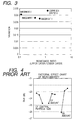
- a graph shown in Fig. 4 shows the findings of an influence which the amount of carbon black (CB), the amount of carbon fiber (CF) respectively contained in the upper layer (the layer touched to the slider) and the central particle size of the carbon fiber (CF) have upon the micro-linearity characteristic in a quality experiment.
- the graph shows that the factor of which the change of the signal-to-noise ratio is larger has a larger influence upon micro-linearity. It is known from the graph shown in Fig. 4 that the factor which has the largest influence upon micro-linearity is the amount of carbon black contained in the upper layer.
- Fig. 5 is a graph showing the relation between the resistivity of the upper layer which is the face where the slider is slid and the micro-linearity characteristic when the central particle size range of the carbon fiber contained in the upper layer is 1.4 ⁇ m or 8.7 ⁇ m. As described later, the smaller variation is, the better the micro-linearity characteristic is. It is known from a graph shown in Fig. 3 that the smaller the resistivity of the upper layer is, the more the micro-linearity characteristic is enhanced in both cases in the central particle size of the contained carbon fiber.
- the conventional type resistor As in the conventional type resistor, the resistivity of the upper layer which is the face where the slider is slid when the conventional type resistor is composed of two or more layers is set to a higher value than that of the lower layer, the conventional type resistor has a problem that a particularly excellent micro-linearity characteristic cannot be expected and it is difficult to use a variable resistor using such a resistor for a high-precision sensor.
- the conventional type resistor also has a problem that as the upper layer contains no carbon fiber, sufficient durability to sliding is not acquired.
- the object of the invention is to provide a resistor excellent in micro-linearity characteristic and further, durability to sliding as well as a high-precision variable resistor using the resistor and having a long life.
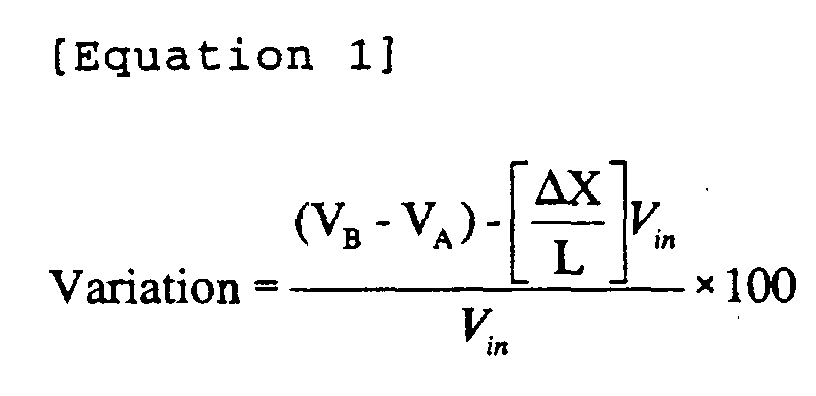
- the variation of the actual output S from the ideal straight line P is defined as a difference between the output displacement VB - VA of each actual output Va and VB at the points A and B and reference output displacement shown by the percentage of applied voltage, and the smaller the variation is, the better the micro-linearity characteristic is.
- a particularly excellent micro-linearity characteristic that actual output S is close to the ideal straight line P is required for a high-performance positional sensor.
- first and second resistors contain conductive particles in binder resin
- the second resistor contains carbon fiber and carbon black
- the central particle size range of the carbon fiber contained in the second resistor is 3.5 to 9.0 ⁇ m
- resistivity of the second resistor is smaller than that of the first resistor
- at least the first and second resistors are laminated
- the second resistor covers an upside of the first resistor and a surface is formed of the second resistor.
- the conductive particles serve to apply conductivity to the first and second resistors.
- binder resin has only to serve to uniformly disperse the conductive particles and to bind these
- the material is not limited and for example, thermosetting resin such as phenol-formaldehyde resin, xylene denatured phenol resin, epoxy resin, polyimide resin, melamine resin, acrylic resin, acrylate resin, furfuryl resin and polyimide resin and others can be used.
- the carbon black contained in the second resistor is conductive particles for applying conductivity to the second resistor, and acetylene black, furnace black, channel black and others can be used.
- the resistivity of the second resistor can be regulated by the percentage content of the carbon black.
- the carbon fiber contained in the second resistor is conductive particles and serves to apply conductivity to the second resistor, to disperse and support a load applied to the resistor by the slider in a direction of fiber length and to enhance the durability to the sliding of the slider of the resistor. Therefore, the resistor is not shaved by the slider and no variation of the electric characteristic by the shaving of the resistor occurs.
- the carbon fiber which is conductive particles supports the load of the slider in the resistor according to the invention, electric contact between the resistor and the slider is stabilized. If the central particle size of the carbon fiber is smaller than 3.5 ⁇ m, the load cannot be supported.
- Such a resistor can have a desired value by reducing the resistivity of the second resistor on which the slider is slid, reducing contact resistance between the slider and the resistor, enhancing the micro-linearity characteristic of the resistor and regulating the resistance value of the whole resistor by the resistivity of the first resistor because the resistor is provided with at least the first and second resistors.
- the first resistor contains carbon fiber and carbon black.
- the carbon black contained in the first resistor is a conductive particle that applies conductivity to the first resistor and the resistivity of the first resistor can be regulated by the percentage content of the carbon black.
- the carbon black acetylene black, furnace black, channel black and others can be used.
- the carbon fiber contained in the first resistor is a conductive particle that applies conductivity to the first resistor and serves to enhance the hardness of the first resistor, to support the second resistor and to prevent the second resistor from sinking when the second resistor is pressed by the slider.
- a central particle size of the carbon fiber contained in the first resistor is equal to or smaller than that of the carbon fiber contained in the second resistor.
- the second resistor contains carbon fiber by 16 to 20 % by volume.
- the percentage content of the carbon fiber in the second resistor is 20 % by volume or less, it is suitable for patterning in the screen printing process.
- a ratio of the resistivity of the second resistor to the resistivity of the first resistor is equal to or larger than 0.1 and is smaller than 1.
- a surface of the second resistor is smoothed and maximum surface roughness is set to 0.5 ⁇ m or less.
- variable resistor uses the abovementioned resistor and a slider made of metal is slid on the surface of the second resistor.
- variable resistor As the durability of the surface of the resistor on which the slider is slid to sliding is excellent, the variable resistor has a long life and as the micro-linearity characteristic of the resistor is satisfactory, it can be used for a high-precision sensor.
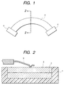
- the embodiment of the resistor according to the invention has a two-layer structure in which a lower layer 2 which is a first resistor and an upper layer 3 which is a second resistor are sequentially laminated in a concave portion of base material 1 as shown in Fig. 2 and is set to a predetermined resistance value as a whole.
- the lower layer 2 contains carbon black (acetylene black) or carbon black and carbon fiber in acetylene terminal polyimide resin which functions as binder.
- the carbon black and the carbon fiber serve to apply conductivity to the lower layer 2 as conductive particles and particularly, the resistivity of the lower layer 2 can be regulated by the percentage content of carbon black.
- Acetylene terminal polyimide resin which functions as binder serves to uniformly disperse carbon black and carbon fiber in the lower layer 2 and bind these.
- the percentage content of carbon black in the lower layer 2 is 10 to 15 % by volume.
- the percentage content of the carbon fiber (hereinafter called first carbon fiber) contained in the lower layer 2 is 10 to 16 % by volume and the central particle size range of the first carbon fiber is 1.4 to 3.4 ⁇ m.
- the central particle size of the carbon fiber means the central particle size of distribution when normal distribution can be applied to the particle size distribution of the carbon fiber.
- the first carbon fiber is acquired by grinding commercial carbon fiber (for example, Torayca MLD product of Toray, and Besfight HTA-CMF product of Toho Rayon) of which the fiber size is approximately 8 ⁇ m and of which the fiber length ranges from 10 ⁇ m to approximately 100 ⁇ m (central particle size: 20 ⁇ m).
- commercial carbon fiber for example, Torayca MLD product of Toray, and Besfight HTA-CMF product of Toho Rayon
- the fiber size is approximately 8 ⁇ m and of which the fiber length ranges from 10 ⁇ m to approximately 100 ⁇ m (central particle size: 20 ⁇ m).
- a jet mill grinding method is used and for a grinding condition, commercial carbon fiber is thrown at the rate of 1 to 3 g per minute, making the compressed air of 6 to 7 kg/cm 2 flow into a cyclone having the size of 150 mm at the rate of 0.2 to 0.6 m 3 per minute.
- first carbon fiber After carbon fiber on the market is ground, it is mixed with water and ethanol by a coupling agent such as aminosilanate and after it is stirred for approximately two hours, it is filtered and is dried at approximately 100 °C.
- a coupling agent such as aminosilanate
- a silanate, titanate or alumina coupling agent can be also used.
- the dispersibility and adhesiveness of the first carbon fiber in/to binder resin are enhanced by such a coupling process.
- the upper layer 3 contains carbon black (acetylene black) of 15 to 20 % by volume and carbon fiber of 10 to 20 % by volume in acetylene terminal polyimide resin which functions as binder.
- the surface of the upper layer 3 is at the substantially same level as the surface of the base material 1 and the maximum surface roughness is 0.5 ⁇ m or less.
- the carbon black and the carbon fiber serve to apply conductivity to the upper layer 3 as a conductive particle and particularly, the resistivity of the upper layer 3 can be adjusted according to the percentage content of carbon black.
- the central particle size range of carbon fiber contained in the upper layer 3 (hereinafter called second carbon fiber) is 7.2 to 9.0 ⁇ m and is acquired by grinding carbon fiber on the market and applying a coupling process to it like the first carbon fiber.
- Acetylene terminal polyimide resin which functions as binder resin serves to uniformly disperse carbon black and carbon fiber in the upper layer 3 and to bind these.
- Resistant paste for the upper layer is acquired by adding acetylene black, the second carbon fiber and a printable modifier if necessary in a solvent in which acetylene terminal polyimide resin is dissolved, mixing and dispersing them using three roll mills.
- the solvent has only to be something to dissolve acetylene terminal polyimide resin and one or more types of glycol, ester, ether and others may be used.
- the resistant paste for the upper layer is patterned on the smooth surface of a metallic plate by screen printing.
- the percentage content of the second carbon fiber in the upper layer 3 is 20 % by volume or less, the second carbon fiber is prevented from getting out of binder resin and projecting out of a pattern.
- the upper layer 3 is completed by applying a heating process at 200 °C for thirty minutes, drying and hardening the resistant paste for the upper layer. At this time, as the solvent is volatilized by the heating process, the upper layer 3 contains no solvent component.
- the lower layer 2 is laminated on the upper layer 3 and is formed as the upper layer 3.
- the upper layer 3 and the lower layer 2 are transferred from the metallic plate and the base material 1.
- the surface of the upper layer 3 is smooth because the surface of the metallic plate is smooth, and the maximum surface roughness is inhibited so that it is 0.5 ⁇ m or less.
- the percentage content of the second carbon fiber in the upper layer 3 is 20 % by volume or less, the second carbon fiber is prevented from getting out of binder resin and projecting from the surface of the upper layer 3.
- a variable resistor according to the invention uses the abovementioned resistor, when the resistor is used for a rotary variable resistor, it is formed in the shape of a resistor pattern P in the shape of an arc shown in Fig. 1 and when the resistor is used for a slide type variable resistor, it is elongated.
- a silver electrode 4 is connected to both ends of such a resistor pattern P and a slider 5 made of noble metal is mounted so that it is slid on the upper layer 3 and is moved along the resistor pattern P.
- variable resistor When such a variable resistor is driven, constant voltage is applied from the silver electrode 4 to the resistor pattern P and the position of the slider 5 on the resistor pattern P is detected in the reference position of the resistor pattern P based upon an output voltage signal between a fixed contact (not shown) electrically connected to the resistor pattern P and the slider moved on the resistor pattern P.
- the second carbon fiber contained in the upper layer 3 serves to support a load applied to the resistor by the slider, the durability to the sliding of the slider 5 of the resistor is enhanced.
- the first carbon fiber contained in the lower layer 2 enhances the hardness of the lower layer 2, supports the upper layer 3 and prevents the upper layer 3 from sinking by the pressure of the slider 5.
- each resistivity of the upper layer 3 and the lower layer 2 can be regulated by the percentage content of carbon black respectively contained in them.
- the resistance value of the whole resistor composed of the upper layer 3 and the lower layer 2 can be set to a desired value by regulating the resistivity of the lower layer 2.
- the micro-linearity characteristic of the resistor is influenced by the central particle size of the carbon fiber respectively contained in the upper layer 3 and the lower layer 2.
- the carbon fiber has anisotropy in conduction that a current is liable to flow in the direction of fiber length
- the resistivity minutely varies for every current path depending upon the degree of the orientation in the direction of the fiber length of the carbon fiber in the current path when the upper layer 3 or the lower layer 2 contains the carbon fiber of which the central particle size is large, and the micro-linearity characteristic is deteriorated.
- Table 1 shows the configuration of the resistor in first to ninth embodiments of the invention.
- resistors are formed as the resistor pattern P in the shape of an arc of which the radius is approximately 7 mm as shown in Figs. 1 and 2, the thickness of the upper layer 3 is set to approximately 5 ⁇ m, the thickness of the lower layer 2 is set to approximately 5 ⁇ m and the resistance value of the whole is set to 2.4 k ⁇ .
- the silver electrode 4 is connected to both ends of the resistor pattern P.
- the slider 5 is made of an alloy including six elements and is revolved on the resistor pattern P.
- the total angle of rotation of the slider 5 for the resistor pattern P is approximately 120°.
- a method of measuring the micro-linearity characteristic will be described below.
- an ideal straight line of the micro-linearity characteristic has the inclination of 42 mV/deg. from a reference point at which the rotation angle of the slider is 10° and the output of which is 0.5 V.
- the output is measured every time the slider is revolved by 0.1 deg. and the magnitude of a range in which the output of measurement varies for the ideal straight line is shown as the percentage of the applied voltage 5V. It can be said that the smaller the variation is, the better the micro-linearity characteristic is.
- Fig. 3 is a graph showing an influence of the resistivity of the upper layer 3 to that of the lower layer 2 upon the micro-linearity characteristic in the sixth, seventh and fifth embodiments and the comparative example 6 shown in Table 1.
- the ratio of the resistance the upper layer/the lower layer
- the micro-linearity characteristic is enhanced, however, when the ratio of the resistance (the upper layer/the lower layer) further decreases from that in the seventh embodiment to that in the sixth embodiment, the micro-linearity characteristic is slightly deteriorated.
- the ratio of the resistivity of the upper layer 3 to that of the lower layer 2 is 0.1 or more.
- the first and second resistors forming the resistor according to the invention contain conductive particles in binder resin, the second resistor contains carbon fiber and carbon black, the central particle size range of the carbon fiber contained'in the second resistor is 3.5 to 9.0 ⁇ m, the resistivity of the second resistor is smaller than the resistivity of the first resistor, at least the first and second resistors are laminated, the second resistor covers the upside of the first resistor and the surface is formed by the second resistor.
- the resistor can have a desired value by reducing the resistivity of the second resistor on which the slider is slid, enhancing the micro-linearity characteristic of the resistor and regulating the resistance value of the whole resistor by the first resistor of which the resistivity is large.
- the carbon fiber contained in the second resistor is conductive particles, applies conductivity to the second resistor and can disperse and support a load applied from the slider to the resistor in the direction of fiber length. Therefore, the durability of the resistor to the load of the slider is enhanced and the characteristic is also kept even if the ambient temperature varies. Electric contact between the resistor and the slider is stabilized because the carbon fiber which is conductive particles supports the load of the slider.
Landscapes
- Engineering & Computer Science (AREA)
- Microelectronics & Electronic Packaging (AREA)
- Adjustable Resistors (AREA)
- Non-Adjustable Resistors (AREA)
Abstract
Description
- VA:
- Output value when slider is positioned at point A
- VB:
- Output value when slider is positioned at point B
- Vin:
- Applied voltage in longitudinal L-direction of resistor
- ΔX:
- Distance between point A and point B
- L:
- Resistor length

Claims (7)
- A resistor,wherein first and second resistors contain conductive particles in binder resinwherein the second resistor contains carbon fiber and carbon black,wherein a central particle size range of the carbon fiber contained in the second resistor is 3.5 to 9.0 µm,wherein the resistivity of the second resistor is smaller than that of the first resistor,wherein at least the first and second resistors are laminated,wherein the second resistor covers an upside of the first resistor, andwherein a surface is formed of the second resistor.
- A resistor according to Claim 1, wherein the first resistor contains carbon fiber and carbon black.
- A resistor according to Claim 2, wherein a central particle size of the carbon fiber contained in the first resistor is equal to or smaller than that of the carbon fiber contained in the second resistor.
- A resistor according to any of Claims 1 to 3, wherein the second resistor contains carbon fiber by 16 to 20 % by volume.
- A resistor according to any of Claims 1 to 4, wherein a ratio of the resistivity of the second resistor to the resistivity of the first resistor is equal to or larger than 0.1 and is smaller than 1.
- A resistor according to any of Claims 1 to 5,wherein a surface of the second resistor is smoothed, andwherein the maximum surface roughness is 0.5 µm or less.
- A variable resistor, wherein the resistor according to any of Claims 1 to 6 is used, and
wherein a slider made of metal is slid on the surface of the second resistor.
Applications Claiming Priority (2)
| Application Number | Priority Date | Filing Date | Title |
|---|---|---|---|
| JP2000337261 | 2000-10-31 | ||
| JP2000337261A JP2002141210A (en) | 2000-10-31 | 2000-10-31 | Resistor and variable resistor using the same |
Publications (3)
| Publication Number | Publication Date |
|---|---|
| EP1202294A2 true EP1202294A2 (en) | 2002-05-02 |
| EP1202294A3 EP1202294A3 (en) | 2004-07-14 |
| EP1202294B1 EP1202294B1 (en) | 2005-12-28 |
Family
ID=18812674
Family Applications (1)
| Application Number | Title | Priority Date | Filing Date |
|---|---|---|---|
| EP01125168A Expired - Lifetime EP1202294B1 (en) | 2000-10-31 | 2001-10-23 | Precision resistor body and variable resistor comprising it |
Country Status (5)
| Country | Link |
|---|---|
| US (1) | US6507271B2 (en) |
| EP (1) | EP1202294B1 (en) |
| JP (1) | JP2002141210A (en) |
| KR (1) | KR100418449B1 (en) |
| DE (1) | DE60116233T2 (en) |
Families Citing this family (6)
| Publication number | Priority date | Publication date | Assignee | Title |
|---|---|---|---|---|
| JP3978380B2 (en) * | 2002-08-12 | 2007-09-19 | アルプス電気株式会社 | Variable resistor |
| US7079005B2 (en) * | 2003-12-01 | 2006-07-18 | Cochran Gary D | Mechanically buffered contact wiper |
| KR101185778B1 (en) * | 2012-05-10 | 2012-10-02 | 국방과학연구소 | Potentiometer |
| JPWO2016067769A1 (en) * | 2014-10-31 | 2017-07-27 | 株式会社村田製作所 | Rotating variable resistor and method for manufacturing the same |
| US10244301B2 (en) | 2016-10-27 | 2019-03-26 | Starkey Laboratories, Inc. | Power management shell for ear-worn electronic device |
| JP7495284B2 (en) | 2020-07-02 | 2024-06-04 | 株式会社ミクニ | Position Sensors |
Family Cites Families (9)
| Publication number | Priority date | Publication date | Assignee | Title |
|---|---|---|---|---|
| US3602861A (en) * | 1969-03-05 | 1971-08-31 | Bourns Inc | Hybrid element variable resistor |
| US4345236A (en) * | 1980-12-29 | 1982-08-17 | General Electric Company | Abrasion-resistant screen-printed potentiometer |
| JPH0696352B2 (en) * | 1985-01-17 | 1994-11-30 | 凸版印刷株式会社 | Plate material for electrostatic printing |
| US4647900A (en) * | 1985-08-16 | 1987-03-03 | Rca Corporation | High power thick film resistor |
| JPH03211706A (en) * | 1990-01-16 | 1991-09-17 | Matsushita Electric Ind Co Ltd | Resistor |
| US5111178A (en) * | 1990-06-15 | 1992-05-05 | Bourns, Inc. | Electrically conductive polymer thick film of improved wear characteristics and extended life |
| JP2889792B2 (en) * | 1993-07-01 | 1999-05-10 | アルプス電気株式会社 | Variable resistor |
| JP3372636B2 (en) * | 1994-03-16 | 2003-02-04 | アルプス電気株式会社 | Manufacturing method of resistive substrate |
| JP3587730B2 (en) | 1999-05-25 | 2004-11-10 | アルプス電気株式会社 | Resistor and variable resistor using the resistor |
-
2000
- 2000-10-31 JP JP2000337261A patent/JP2002141210A/en not_active Withdrawn
-
2001
- 2001-10-23 DE DE60116233T patent/DE60116233T2/en not_active Expired - Fee Related
- 2001-10-23 EP EP01125168A patent/EP1202294B1/en not_active Expired - Lifetime
- 2001-10-30 US US10/001,130 patent/US6507271B2/en not_active Expired - Fee Related
- 2001-10-30 KR KR10-2001-0067188A patent/KR100418449B1/en not_active Expired - Fee Related
Also Published As
| Publication number | Publication date |
|---|---|
| EP1202294B1 (en) | 2005-12-28 |
| US6507271B2 (en) | 2003-01-14 |
| JP2002141210A (en) | 2002-05-17 |
| KR100418449B1 (en) | 2004-02-14 |
| DE60116233T2 (en) | 2006-08-31 |
| DE60116233D1 (en) | 2006-02-02 |
| KR20020033578A (en) | 2002-05-07 |
| EP1202294A3 (en) | 2004-07-14 |
| US20020075130A1 (en) | 2002-06-20 |
Similar Documents
| Publication | Publication Date | Title |
|---|---|---|
| US20050128047A1 (en) | Pressure-sensitive resistor and pressure-sensitive sensor using the same | |
| TW584735B (en) | Sensor for measuring a magnetic field and method of regulating said sensor | |
| EP1202294B1 (en) | Precision resistor body and variable resistor comprising it | |
| JP2010501675A (en) | Highly filled thermoplastic composite material | |
| JP2889792B2 (en) | Variable resistor | |
| JP2012057991A (en) | Pressure sensitive sensor | |
| US6172595B1 (en) | Resistor excellent in micro-linearity characteristic and wear resistance and variable resistor using the same | |
| EP3861061B1 (en) | Force or pressure sensing composite material | |
| US6891465B2 (en) | Variable-resistance element | |
| EP1074997A2 (en) | Conductive resin composition and encoder switch using the same | |
| DE102009020743A1 (en) | Photolithographically structured thick-film sensor | |
| US20040217844A1 (en) | Thick film thermistor and method of manufacture | |
| JP4008997B2 (en) | Semiconductive ceramics, jigs and tools using the same, magnetic disk substrate holding member, and magnetic disk device | |
| US6815039B2 (en) | Resistance element for potentiometric devices, and method of manufacture | |
| JPH0642189B2 (en) | Touch panel | |
| EP1086472B1 (en) | Temperature probe, comprising at least one conductor strip and a method for producing a probe of this type | |
| Wassmer et al. | Inkjet Printing of Thick-Film Resistors | |
| JPH08231757A (en) | Slide rheostat | |
| Hao et al. | Printing Characteristics and Performance of Polymer Thick Film Inks for Direct Write Applications | |
| JPH07326020A (en) | Method of manufacturing thin film magnetic head | |
| JPH0270770A (en) | silver paste |
Legal Events
| Date | Code | Title | Description |
|---|---|---|---|
| PUAI | Public reference made under article 153(3) epc to a published international application that has entered the european phase |
Free format text: ORIGINAL CODE: 0009012 |
|
| AK | Designated contracting states |
Kind code of ref document: A2 Designated state(s): AT BE CH CY DE DK ES FI FR GB GR IE IT LI LU MC NL PT SE TR |
|
| AX | Request for extension of the european patent |
Free format text: AL;LT;LV;MK;RO;SI |
|
| PUAL | Search report despatched |
Free format text: ORIGINAL CODE: 0009013 |
|
| AK | Designated contracting states |
Kind code of ref document: A3 Designated state(s): AT BE CH CY DE DK ES FI FR GB GR IE IT LI LU MC NL PT SE TR |
|
| AX | Request for extension of the european patent |
Extension state: AL LT LV MK RO SI |
|
| RIC1 | Information provided on ipc code assigned before grant |
Ipc: 7H 01C 10/30 B Ipc: 7H 01C 7/00 A |
|
| 17P | Request for examination filed |
Effective date: 20040722 |
|
| GRAP | Despatch of communication of intention to grant a patent |
Free format text: ORIGINAL CODE: EPIDOSNIGR1 |
|
| RTI1 | Title (correction) |
Free format text: PRECISION RESISTOR BODY AND VARIABLE RESISTOR COMPRISING IT |
|
| AKX | Designation fees paid |
Designated state(s): DE FR GB |
|
| RTI1 | Title (correction) |
Free format text: PRECISION RESISTOR BODY AND VARIABLE RESISTOR COMPRISING IT |
|
| GRAS | Grant fee paid |
Free format text: ORIGINAL CODE: EPIDOSNIGR3 |
|
| RBV | Designated contracting states (corrected) |
Designated state(s): DE FR GB |
|
| GRAA | (expected) grant |
Free format text: ORIGINAL CODE: 0009210 |
|
| AK | Designated contracting states |
Kind code of ref document: B1 Designated state(s): DE FR GB |
|
| REG | Reference to a national code |
Ref country code: GB Ref legal event code: FG4D |
|
| REF | Corresponds to: |
Ref document number: 60116233 Country of ref document: DE Date of ref document: 20060202 Kind code of ref document: P |
|
| ET | Fr: translation filed | ||
| PGFP | Annual fee paid to national office [announced via postgrant information from national office to epo] |
Ref country code: GB Payment date: 20061024 Year of fee payment: 6 |
|
| PLBE | No opposition filed within time limit |
Free format text: ORIGINAL CODE: 0009261 |
|
| STAA | Information on the status of an ep patent application or granted ep patent |
Free format text: STATUS: NO OPPOSITION FILED WITHIN TIME LIMIT |
|
| 26N | No opposition filed |
Effective date: 20060929 |
|
| PGFP | Annual fee paid to national office [announced via postgrant information from national office to epo] |
Ref country code: DE Payment date: 20061218 Year of fee payment: 6 |
|
| GBPC | Gb: european patent ceased through non-payment of renewal fee |
Effective date: 20071023 |
|
| PG25 | Lapsed in a contracting state [announced via postgrant information from national office to epo] |
Ref country code: DE Free format text: LAPSE BECAUSE OF NON-PAYMENT OF DUE FEES Effective date: 20080501 |
|
| REG | Reference to a national code |
Ref country code: FR Ref legal event code: ST Effective date: 20080630 |
|
| PGFP | Annual fee paid to national office [announced via postgrant information from national office to epo] |
Ref country code: FR Payment date: 20061020 Year of fee payment: 6 |
|
| PG25 | Lapsed in a contracting state [announced via postgrant information from national office to epo] |
Ref country code: GB Free format text: LAPSE BECAUSE OF NON-PAYMENT OF DUE FEES Effective date: 20071023 |
|
| PG25 | Lapsed in a contracting state [announced via postgrant information from national office to epo] |
Ref country code: FR Free format text: LAPSE BECAUSE OF NON-PAYMENT OF DUE FEES Effective date: 20071031 |