EP1202132A1 - Fixing roller, fixing apparatus using the fixing roller and image forming apparatus using the fixing apparatus - Google Patents
Fixing roller, fixing apparatus using the fixing roller and image forming apparatus using the fixing apparatus Download PDFInfo
- Publication number
- EP1202132A1 EP1202132A1 EP01125384A EP01125384A EP1202132A1 EP 1202132 A1 EP1202132 A1 EP 1202132A1 EP 01125384 A EP01125384 A EP 01125384A EP 01125384 A EP01125384 A EP 01125384A EP 1202132 A1 EP1202132 A1 EP 1202132A1
- Authority
- EP
- European Patent Office
- Prior art keywords
- fixing roller
- fixing
- roller
- recording sheet
- wall thickness
- Prior art date
- Legal status (The legal status is an assumption and is not a legal conclusion. Google has not performed a legal analysis and makes no representation as to the accuracy of the status listed.)
- Granted
Links
Images



Classifications
-
- G—PHYSICS
- G03—PHOTOGRAPHY; CINEMATOGRAPHY; ANALOGOUS TECHNIQUES USING WAVES OTHER THAN OPTICAL WAVES; ELECTROGRAPHY; HOLOGRAPHY
- G03G—ELECTROGRAPHY; ELECTROPHOTOGRAPHY; MAGNETOGRAPHY
- G03G15/00—Apparatus for electrographic processes using a charge pattern
- G03G15/20—Apparatus for electrographic processes using a charge pattern for fixing, e.g. by using heat
- G03G15/2003—Apparatus for electrographic processes using a charge pattern for fixing, e.g. by using heat using heat
- G03G15/2014—Apparatus for electrographic processes using a charge pattern for fixing, e.g. by using heat using heat using contact heat
- G03G15/2053—Structural details of heat elements, e.g. structure of roller or belt, eddy current, induction heating
Definitions
- the present invention relates to a fixing roller, a fixing apparatus using the fixing roller and for use in an image forming apparatus and an image forming apparatus using the fixing apparatus, and in particular relates to a structure for reinforcing a fixing or heating roller of a fixing apparatus.
- image forming apparatuses such as copying machines, facsimile apparatuses, printers, printing apparatuses, etc.
- an unfixed toner image transferred onto and carried on a recording medium such as paper is heated by a fixing apparatus so as to be fixed onto the recording medium, and thereby a reproduced or printed image is obtained on the recording medium.
- a known fixing apparatus has a configuration in which a pair of rollers are arranged so as to oppose each other.
- One of the rollers is used as a heating roller or a fixing roller for heating a recording medium and the other roller is used as a pressing roller for pressing the recording medium against the heating roller.
- the recording medium is conveyed while being sandwiched between the heating roller and the pressing roller at a nip portion between the heating roller and the pressing roller, and thereby an unfixed toner image carried on the recording medium is fixed onto the recording medium by heat from the heating roller.
- the heating roller In order to accomplish efficient fixing in such a fixing apparatus, it is important to increase heat transmission efficiency of the heating roller by using material having a satisfactory heat conductivity for the heating roller.
- the heating roller is generally designed in such a manner by which the heat conductivity is increased.
- wall thickness of the heating roller is made thin so that the heat capacitance of the heating roller is reduced, thereby enabling shortening of the rising time of the heating roller to reach a fixing temperature and reducing of the power consumption of the heating roller.
- a heating roller when a heating roller is constructed so as to have a thin wall, the mechanical rigidity of the heating roller is decreased, so that bending may occur in the heating roller or a portion of the heating roller pressed by a pressing roller may be crushed in an axial direction of the heating roller.
- separate reinforcing members such as rings are arranged so as to be fixed to internal surfaces of the heating roller at a plurality of positions of the heating roller, e.g., at a center part and end parts of the heating roller in an axial direction thereof, where the heating roller most likely tends to be crushed.
- the reinforcing rings must be processed separately from the heating roller, thereby causing increase in the cost of the heating roller.
- the rings may be deformed due to thermal expansion thereof, thereby falling off the internal surfaces of the heating roller. As a result, deformation such as bending or crushing of the heating roller cannot be avoided. If the heating roller is deformed, the force of sandwiching a recording medium with the fixing roller and the pressing roller is decreased, and thereby the efficiency of heating the recording sheet with the heating roller is decreased, and consequently inferior fixing is caused.
- the reinforcing rings are arranged at a plurality of positions of a heating roller in an axial direction thereof, depending upon the number of the rings that are provided, heat loss may be caused by heat dissipation via the reinforcing rings, which may also cause decrease in the efficiency of heating the recording medium with the heating roller and consequent inferior fixing.
- the present invention has been made in view of the above-discussed and other problems and addresses the above-discussed and other problems.
- Preferred embodiments of the present invention provide a novel fixing roller, a novel fixing apparatus using the fixing roller and an image forming apparatus using the fixing apparatus, in which increase of processing cost of a fixing roller or heating roller and falling off of reinforcing members for the heating roller are prevented and at the same time the rising time of the fixing apparatus to a fixing temperature can be decreased and inferior fixing is suppressed.
- a fixing roller for use in a fixing apparatus for fixing a toner image carried on a recording sheet onto the recording sheet with heat includes a plurality of ribs formed at a sheet passing area of the fixing roller in an axial direction of the fixing roller so as to protrude from an internal circumferential surface of the fixing roller toward a cross sectional center thereof.
- the plurality of ribs are provided along the axial direction of the fixing roller such that a number of ribs per a unit length at a center part of the sheet passing area of the fixing roller in the axial direction of the fixing roller is different from that at other parts of the sheet passing area.
- a heating source for heating the fixing roller is provided.
- a fixing apparatus for fixing a toner image carried on a recording sheet onto the recording sheet with heat includes a fixing roller having a plurality of ribs formed at a sheet passing area of the fixing roller in an axial direction of the fixing roller so as to protrude from an internal circumferential surface of the fixing roller toward a cross sectional center thereof.
- the plurality of ribs are provided along the axial direction of the fixing roller such that a number of ribs per a unit length at a center part of the sheet passing area of the fixing roller in the axial direction of the fixing roller is different from that at other parts of the sheet passing area.
- the fixing apparatus further includes a heating source for heating the fixing roller and a pressing roller opposing and rotating with the fixing roller, and the toner image on the recording sheet is fixed onto the recording sheet while the recording sheet is being sandwiched and conveyed between the fixing roller and the pressing roller.
- the heating source may be provided inside of the fixing roller.
- the number of ribs per a unit length may be greater at the center part of the sheet passing area of the fixing roller in the axial direction of the fixing roller than at the other parts of the sheet passing area.
- a center of the fixing roller in the axial direction thereof may correspond to a center of the sheet passing area of the fixing roller in the axial direction of the fixing roller.
- the fixing roller may have a first wall thickness at the sheet passing area thereof and a second wall thickness at least at a part of axial end parts thereof that are out of the sheet passing area.
- the second wall thickness is greater than the first wall thickness.
- the above-described fixing apparatus may further include a supporting member opposing a part of the axial end parts of the fixing roller to support the fixing roller.
- the part of the axial end parts of the fixing roller where the fixing roller supporting member opposes does not have the second wall thickness.
- a rib may be formed at the part of the axial end parts of the fixing roller where the fixing roller supporting member opposes so as to protrude from the internal circumferential surface of the fixing roller toward the cross sectional center thereof.
- a height from the internal circumferential surface of the fixing roller, of the rib formed at the part of the axial end parts of the fixing roller where the fixing roller supporting member opposes so as to protrude from the internal circumferential surface of the fixing roller toward the cross sectional center thereof is different from that of the part of the axial end parts of the fixing roller having the second wall thickness.
- the height from the internal circumferential surface of the fixing roller, of the rib formed at the part of the axial end parts of the fixing roller where the fixing roller supporting member opposes may be equal to that of the plurality of ribs formed at the sheet passing area of the fixing roller.
- an image forming apparatus includes an image forming unit for forming a toner image on a recording sheet and a fixing apparatus for fixing the toner image on the recording sheet onto the recording sheet with heat.
- the fixing apparatus includes a fixing roller having a plurality of ribs formed at a sheet passing area of the fixing roller in an axial direction of the fixing roller so as to protrude from an internal circumferential surface of the fixing roller toward a cross sectional center thereof.
- the plurality of ribs are provided along the axial direction of the fixing roller such that a number of ribs per a unit length at a center part of the sheet passing area of the fixing roller in the axial direction of the fixing roller is different from that at other parts of the sheet passing area.
- the fixing apparatus further includes a heating source for heating the fixing roller and a pressing roller opposing and rotating with the fixing roller, and the toner image on the recording sheet is fixed onto the recording sheet while the recording sheet is being sandwiched and conveyed between the fixing roller and the pressing roller.
- the heating source may be provided inside of the fixing roller.
- the number of ribs per a unit length may be greater at the center part of the sheet passing area of the fixing roller in the axial direction of the fixing roller than at the other parts of the sheet passing area.
- a center of the fixing roller in the axial direction thereof may correspond to a center of the sheet passing area of the fixing roller in the axial direction of the fixing roller.
- the fixing roller may have a first wall thickness at the sheet passing area thereof and a second wall thickness at least at a part of axial end parts thereof that are out of the sheet passing area.
- the second wall thickness is greater than the first wall thickness.
- the fixing apparatus may include a supporting member opposing a part of the fixing roller at the axial end parts of the fixing roller to support the fixing roller.
- the part of the axial end parts of the fixing roller where the fixing roller supporting member opposes does not have the second wall thickness.
- a rib may be formed at the part of the axial end parts of the fixing roller where the fixing roller supporting member opposes so as to protrude from the internal circumferential surface of the fixing roller toward the cross sectional center thereof.
- a height from the internal circumferential surface of the fixing roller, of the rib formed at the part of the axial end parts of the fixing roller where the fixing roller supporting member opposes so as to protrude from the internal circumferential surface of the fixing roller toward the cross sectional center thereof is different from that of the part of the axial end parts of the fixing roller, having the second wall thickness.
- the height from the internal circumferential surface of the fixing roller, of the rib formed at the part of the axial end parts of the fixing roller where the fixing roller supporting member opposes may be equal to that of the plurality of ribs formed at the sheet passing area of the fixing roller.
- Fig. 1 illustrates a printer as an example of an image forming apparatus having a fixing apparatus according to a preferred embodiment of the present invention.
- a printer 1 includes a belt-shaped photoconductor 2 (hereinafter referred to as the photoconductor belt 2), and around the photoconductor belt 2 along a moving direction of the photoconductor belt 2 indicated by arrow in the figure, a charging device 3, a writing device 4 having a laser optical system, a developing device 5, a transfer device 6, and a cleaning device 7 are arranged.
- a sheet feeding device 8 which includes a plurality of feeding cassettes 8A and 8A' accommodating recording sheets of a plurality of sizes and a registration roller 9, is arranged near the transfer device 6. Further, a fixing apparatus 10 is arranged at a position where a recording sheet, on which an image has been transferred from the photoconductor belt 2 with the transfer device 6, is separated from the photoconductor belt 2 by curvature of the belt 2, and a sheet discharging device 11 is arranged after the fixing apparatus 10 in the recording sheet conveying direction.
- the photoconductor belt 2 is uniformly charged by the charging device 3 while moving, and then an electrostatic latent image according to image information is formed on the photoconductor belt 2 by the writing device 4.
- the latent image is visualized by the developing device 5, and the visualized image is transferred onto a recording sheet conveyed from the feeding device 8 by the transfer device 6.
- the recording sheet on which an image has been transferred is separated from the photoconductor belt 2 by curvature of the belt 2, and reaches the fixing apparatus 10, where the image is fixed onto the recording sheet.
- the recording sheet is then discharged onto a discharging tray 11A by the discharging device 11.
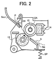
- Fig. 2 illustrates the construction of the fixing apparatus 10.
- the fixing apparatus 10 includes a fixing roller 12 including a heating source 12A inside thereof and a pressing roller 13 opposing and contacting the fixing roller 12 so as to rotate together with the fixing roller 12.
- the fixing roller 12 is made of material having a satisfactory heat conductivity, such as steel (e.g., STKM11, STKM12) or an aluminum alloy, and offset preventing oil (not shown) is coated on its surface.
- a cleaning pad 14 is pressed against the fixing roller 12 to remove surplus oil on the fixing roller 12.
- the pressing roller 13 has the diameter of 30mm.
- the pressing roller 13 may be configured to have rubber, which is 5.5mm thick and 316mm long in its axial direction, on its surface, or to be a solid roller without having such rubber.
- a reference S denotes a recording sheet carrying an unfixed image thereupon
- a reference S IN denotes a sheet entrance guide
- a reference S OUT denotes a sheet exit guide
- a reference P denotes a separation claw
- a reference SP denotes a spring pressing the pressing roller 13 toward the fixing roller 12.
- the outer diameter of the fixing roller 12 is set in the range of 16-40mm, and as illustrated in Figs. 3 and 5, the wall thickness (T) of the fixing roller 12 is set in the range of 0.25-0.5mm, and the length of the fixing roller 12 in its axial direction is set in the range of 350-410mm.
- the deformation in a fixing roller when the fixing roller and a pressing roller sandwiches and conveys a recording sheet changes according to the outer diameter of the fixing roller.
- the ratio of the wall thickness relative to the outer diameter of the fixing roller 12 is set in the range of 8/1000-20/1000.
- the ratio of the wall thickness relative to the outer diameter of the fixing roller 12 is set in a range of 8/1000-14/1000
- the ratio of the wall thickness relative to the outer diamter of the fixing roller 12 is set in a range of 12/1000-20/1000.
- the outer diameter of the fixing roller 12 is set to 30mm, and the wall thickness at a sheet passing area of the fixing roller 12 in the axial direction of the fixing roller 12 (the thickness denoted by T in Figs. 3 and 5) is set to 0.3mm, so that the ratio of the wall thickness relative to the outer diameter of the fixing roller 12 is set to 10/1000.
- the fixing roller 12 is made of an aluminum alloy (e.g., A5052)
- the outer diameter of the fixing roller 12 is set to 30mm
- the wall thickness at the sheet passing area of the fixing roller 12 is set to 0.45mm, so that the ratio of the wall thickness relative to the outer diameter of the fixing roller 12 is set to 15/1000.
- Fig. 3 is a cross section of the fixing roller 12. As illustrated in Fig. 3, a plurality of ribs 15, 15' are formed in the sheet passing area of the fixing roller 12 in the axial direction thereof, along the axial direction of the fixing roller 12.
- the ribs 15, 15' are formed such that, irrespective of the material of the fixing roller 12, the width (B) in the axial direction of the fixing roller 12 is set to 1.5-3mm, and the height (H) from the internal circumferential surface of the fixing roller 12 toward the center of the fixing roller 12 in its cross section is set to 0.5mm, which corresponds to 0.8-2.0 times of the wall thickness at the sheet passing area of the fixing roller 12 (the thickness denoted by T in Figs. 3 and 5).
- the ribs 15 which are provided at the center part of the sheet passing area in the axial direction of the fixing roller 12 are arranged with an interval smaller than that of the ribs 15' which are provided at other parts of the sheet passing area of the fixing roller 12.
- the plurality of ribs 15, 15' i.e., three ribs 15 and four ribs 15', are provided such that the interval L of the ribs 15 provided at the center part of the sheet passing area in the axial direction of the fixing roller 12 satisfies a relation: L ⁇ L2 ⁇ L1, where a reference L1 represents an interval of the ribs 15' provided at the other parts of the sheet passing area than the center part thereof and a reference L2 represents an interval between the rib 15 of the center part of the sheet passing area, that is located to face the ribs 15' of the other parts of the sheet passing area, and the ribs 15' of the other area of the sheet passing area, that is located to face the rib 15 of the center part of the sheet passing area.
- the fixing roller 12 is configured such that the wall thickness at its axial end parts (the thickness denoted by T1 in Figs. 3 and 4) is greater than the wall thickness T in the sheet passing area.
- the wall thickness T1 is set such that the ratio of the wall thickness T1 relative to the outer diameter of the fixing roller 12 is set in the range of 16/1000-40/1000.
- the fixing roller 12 is made of steel (e.g., STKM12)
- the wall thickness T1 at the axial end parts is 0.55mm
- the fixing roller 12 is made of an aluminum alloy
- the wall thickness T1 at the axial end parts is 0.9mm.
- the wall thickness of the fixing roller 12 is determined such that a predetermined cross sectional rigidity is obtained in the fixing roller 12.
- the ribs 15 at the center part of the sheet passing area of the fixing roller 12 prevent the fixing roller 12 from being crushed at the center part thereof, thereby avoiding the force of sandwiching a recording sheet between the fixing roller 12 and the pressing roller 13 from being decreased to cause inferior fixing.
- a thick recording sheet e.g., a sheet of 135K, or a recording sheet having an inferior surface smoothness
- the fixing roller 12 is prevented from being crushed at the center part thereof, and thereby inferior fixing is avoided.
- the wall thickness of the fixing roller 12 is smaller at the sheet passing area of the fixing roller 12 in the axial direction of the fixing roller 12 than at the axial end parts of the fixing roller 12, the rising time of the fixing roller 12 to a fixing temperature can be decreased.
- the decrease in the rigidity of the fixing roller 12 at the center part of the sheet passing area of the fixing roller 12 in the axial direction thereof is reinforced by providing more of the ribs 15 to the center part of the sheet passing area than to the other parts of the sheet passing area of the fixing roller 12.
- the ribs 15, 15' serving as reinforcing members for the fixing roller 12 are formed integrally with the fixing roller 12 so as to protrude from an internal circumferential surface toward a center of the cross section of the fixing roller 12. Therefore, unlike a structure in which reinforcing rings, which are separate from a fixing roller, are provided inside of the fixing roller, the reinforcing members, i.e., the ribs 15,15', never fall off the internal surface of the fixing roller 12, and thereby deformation of the fixing roller 12 when the fixing roller 12 is heated, such as bending, can be securely prevented.
- the fixing roller 12 is supported at both end parts thereof by a bearing functioning as a rotation supporting member for the fixing roller 12 as illustrated in Fig. 3.
- a ball bearing 16 is used for the supporting member for the fixing roller 12.
- the linear velocity of a recording sheet is set in the range of about 100-130mm/sec. Therefore, when the fixing roller 12 is used in such a high speed image forming apparatus, the rotation speed of the fixing roller 12 is set at a relatively high speed, and at the same time the driving torque for the fixing roller 12 must be decreased. Because the ball bearing 16 can avoid giving an excessive load to the fixing roller 12, the ball bearing 16 can be advantageously used in such a high speed image forming apparatus.
- the ball bearing 16 is configured to contact an outer circumferential surface of the fixing roller 12 at a part of the axial end parts of the fixing roller 12. Therefore, if the wall thickness of the fixing roller 12 at the part of the axial end parts of the fixing roller 12 where the ball bearing 16 opposes is substantially the same as that of the axial end parts of the fixing roller 12, which is greater than the sheet passing area of the fixing roller 12, heat may be dissipated through the ball bearing 16 contacting the part of the axial end parts of the fixing roller 12 because of a relatively high heat capacity of that part.
- the fixing roller 12 of the present invention is configured such that the above heat dissipation through the ball bearing 16 is prevented.
- the fixing roller 12 is configured such that the wall thickness T1 of both axial end parts of the fixing roller 12 is greater than the wall thickness T of the sheet passing area of the fixing roller 12 except for the part of the axial end parts of the fixing roller 12 where the ball bearing 16 opposes.
- the lengths S1 and S1' of the parts of the axial end parts of the fixing roller 12, having the wall thickness T1 which is greater than the wall thickness T of the sheet passing area of the fixing roller 12, are set to be in the ranges of 5-10mm and 12-16mm from the ends of the fixing roller 12 respectively. These ranges are both smaller than respective distances from the ends of the fixing roller 12 to the parts of the axial end parts of the fixing roller 12 where the ball bearings 16 oppose.
- a rib 17 having a dimension different from that of the part of the axial end parts of the fixing roller 12 having the wall thickness T1 is provided so as to protrude from an internal circumferential surface of the fixing roller 12 toward the center of the cross section of the fixing roller 12.
- the rib 17 is configured in the same height (H) from the internal circumferential surface of the fixing roller 12 toward the center of the cross section of the fixing roller 12 and width (B) in the axial direction of the fixing roller 12 as those of the ribs 15, 15' provided at the sheet passing area of the fixing roller 12.
- the both end parts thicker than the sheet passing area of the fixing roller 12 do not reach the parts of the fixing roller 12 where the ball bearings 16 oppose, respectively.
- the thicker wall having a relatively large heat capacity does not exist, heat conduction at that part is suppressed and thereby heat dissipation through the ball bearing 16 is suppressed.
- the part of the heating roller 12 where the ball bearing 16 opposes is configured so as to be relatively thin as in the sheet passing area of the fixing roller 12, the rising time of the fixing roller 12 to a fixing temperature is decreased, and at the same time decrease in the fixing temperature is prevented, so that inferior fixing is avoided.
- the rib 17 is provided to the part of the fixing roller 12 where the ball bearing 16 opposes, crushing of the fixing roller 12 at the part thereof where the ball bearing 16 opposes due to bending thereof is prevented.
- the rib 17 has the same configuration as those of the ribs 15, 15' provided at the sheet passing area of the fixing roller 12. Therefore, at the part of the fixing roller 12 where the ball bearing 16 opposes, the rib 17 never abnormally increases the force of sandwiching a recording sheet with the fixing roller 12 and the pressing roller 13 as compared at the sheet passing area of the fixing roller 12, and thus such a phenomenon never occurs in which the recording sheet being sandwiched and conveyed between the fixing roller 12 and the pressing roller 13 is pulled at the both end parts of the recording sheet in the widthwise direction thereof. Consequently, occurrence of wrinkling in the recording sheet is suppressed.
- the fixing roller 12 is configured so as to have a thinner wall thickness at the part of the fixing roller 12 where the ball bearing 16 opposes and if the rib 17 is not provided at that part, the fixing roller 12 is easy to be crushed at that part under the influence of increased contacting pressure from the pressing roller 13, and as a result, the surface area of the fixing roller 12 contacting the circumferential surface of the pressing roller 13 increases at the part of the fixing roller 12 where crushed, i.e., the part where the ball bearing 16 opposes, so that a recording sheet is pulled at both widthwise end parts thereof, and thereby the recording sheet tends to be wrinkled.
- the number of ribs provided at the sheet passing area of the fixing roller 12 can be increased at the both axial end parts of the sheet passing area of the fixing roller 12, which however is not desirable from the view point of processing cost for the fixing roller 12.
- the number of ribs at the sheet passing area of the fixing roller 12 is reduced to a level of 3-7 as described above, it is conceivable to extend the both end parts of the fixing roller 12, that have a wall thickness greater that than that of the sheet passing area of the fixing roller 12, toward the part of the fixing roller 12 where the ball bearing 16 opposes, so that the fixing roller 12 is prevented from being crushed at that part of the fixing roller 12 where the ball bearing 16 opposes.
- the number of ribs at the sheet passing area of the fixing roller 12 is set to be in the range of 3-7, and the both end parts of the fixing roller 12 in the axial direction thereof, that have a wall thickness greater than that of the sheet passing area of the fixing roller 12, are configured so as not to extend to the part of the fixing roller 12 where the ball bearing 16 opposes, and the rib 17 having the same configuration as that of the ribs 15, 15' that are provided at the sheet passing area of the fixing roller 12 is provided to the part of the fixing roller 12 where the ball bearing 16 opposes.
- a fixing roller having a heating source inside thereof is used.
- a fixing roller which does not have a heating source inside thereof and which instead is heated by an external heat source can be also used.
- the invention is especially directed to the following subjects:
Landscapes
- Physics & Mathematics (AREA)
- General Physics & Mathematics (AREA)
- Fixing For Electrophotography (AREA)
Abstract
Description
- The present invention relates to a fixing roller, a fixing apparatus using the fixing roller and for use in an image forming apparatus and an image forming apparatus using the fixing apparatus, and in particular relates to a structure for reinforcing a fixing or heating roller of a fixing apparatus.
- In image forming apparatuses, such as copying machines, facsimile apparatuses, printers, printing apparatuses, etc., an unfixed toner image transferred onto and carried on a recording medium such as paper is heated by a fixing apparatus so as to be fixed onto the recording medium, and thereby a reproduced or printed image is obtained on the recording medium.
- A known fixing apparatus has a configuration in which a pair of rollers are arranged so as to oppose each other. One of the rollers is used as a heating roller or a fixing roller for heating a recording medium and the other roller is used as a pressing roller for pressing the recording medium against the heating roller. In this configuration, the recording medium is conveyed while being sandwiched between the heating roller and the pressing roller at a nip portion between the heating roller and the pressing roller, and thereby an unfixed toner image carried on the recording medium is fixed onto the recording medium by heat from the heating roller.
- In order to accomplish efficient fixing in such a fixing apparatus, it is important to increase heat transmission efficiency of the heating roller by using material having a satisfactory heat conductivity for the heating roller. In addition, the heating roller is generally designed in such a manner by which the heat conductivity is increased. As an example, wall thickness of the heating roller is made thin so that the heat capacitance of the heating roller is reduced, thereby enabling shortening of the rising time of the heating roller to reach a fixing temperature and reducing of the power consumption of the heating roller.
- However, when a heating roller is constructed so as to have a thin wall, the mechanical rigidity of the heating roller is decreased, so that bending may occur in the heating roller or a portion of the heating roller pressed by a pressing roller may be crushed in an axial direction of the heating roller.
- In a known construction for avoiding the above-described problem in a heating roller, separate reinforcing members such as rings are arranged so as to be fixed to internal surfaces of the heating roller at a plurality of positions of the heating roller, e.g., at a center part and end parts of the heating roller in an axial direction thereof, where the heating roller most likely tends to be crushed.
- However, in the above-described configuration, the reinforcing rings must be processed separately from the heating roller, thereby causing increase in the cost of the heating roller. In addition, when the heating roller is actually used in an image forming apparatus, the rings may be deformed due to thermal expansion thereof, thereby falling off the internal surfaces of the heating roller. As a result, deformation such as bending or crushing of the heating roller cannot be avoided. If the heating roller is deformed, the force of sandwiching a recording medium with the fixing roller and the pressing roller is decreased, and thereby the efficiency of heating the recording sheet with the heating roller is decreased, and consequently inferior fixing is caused.
- Further, when the reinforcing rings are arranged at a plurality of positions of a heating roller in an axial direction thereof, depending upon the number of the rings that are provided, heat loss may be caused by heat dissipation via the reinforcing rings, which may also cause decrease in the efficiency of heating the recording medium with the heating roller and consequent inferior fixing.
- The present invention has been made in view of the above-discussed and other problems and addresses the above-discussed and other problems.
- Preferred embodiments of the present invention provide a novel fixing roller, a novel fixing apparatus using the fixing roller and an image forming apparatus using the fixing apparatus, in which increase of processing cost of a fixing roller or heating roller and falling off of reinforcing members for the heating roller are prevented and at the same time the rising time of the fixing apparatus to a fixing temperature can be decreased and inferior fixing is suppressed.
- According to a preferred embodiment of the present invention a fixing roller for use in a fixing apparatus for fixing a toner image carried on a recording sheet onto the recording sheet with heat includes a plurality of ribs formed at a sheet passing area of the fixing roller in an axial direction of the fixing roller so as to protrude from an internal circumferential surface of the fixing roller toward a cross sectional center thereof. The plurality of ribs are provided along the axial direction of the fixing roller such that a number of ribs per a unit length at a center part of the sheet passing area of the fixing roller in the axial direction of the fixing roller is different from that at other parts of the sheet passing area.
- A heating source for heating the fixing roller is provided.
- According to a further preferred embodiment of the present invention, a fixing apparatus for fixing a toner image carried on a recording sheet onto the recording sheet with heat includes a fixing roller having a plurality of ribs formed at a sheet passing area of the fixing roller in an axial direction of the fixing roller so as to protrude from an internal circumferential surface of the fixing roller toward a cross sectional center thereof. The plurality of ribs are provided along the axial direction of the fixing roller such that a number of ribs per a unit length at a center part of the sheet passing area of the fixing roller in the axial direction of the fixing roller is different from that at other parts of the sheet passing area. The fixing apparatus further includes a heating source for heating the fixing roller and a pressing roller opposing and rotating with the fixing roller, and the toner image on the recording sheet is fixed onto the recording sheet while the recording sheet is being sandwiched and conveyed between the fixing roller and the pressing roller.
- In the above-described fixing apparatus, the heating source may be provided inside of the fixing roller.
- Further, the number of ribs per a unit length may be greater at the center part of the sheet passing area of the fixing roller in the axial direction of the fixing roller than at the other parts of the sheet passing area.
- Furthermore, a center of the fixing roller in the axial direction thereof may correspond to a center of the sheet passing area of the fixing roller in the axial direction of the fixing roller.
- Still further, the fixing roller may have a first wall thickness at the sheet passing area thereof and a second wall thickness at least at a part of axial end parts thereof that are out of the sheet passing area. The second wall thickness is greater than the first wall thickness.
- Furthermore, the above-described fixing apparatus may further include a supporting member opposing a part of the axial end parts of the fixing roller to support the fixing roller. In this case, the part of the axial end parts of the fixing roller where the fixing roller supporting member opposes does not have the second wall thickness. Further, a rib may be formed at the part of the axial end parts of the fixing roller where the fixing roller supporting member opposes so as to protrude from the internal circumferential surface of the fixing roller toward the cross sectional center thereof. A height from the internal circumferential surface of the fixing roller, of the rib formed at the part of the axial end parts of the fixing roller where the fixing roller supporting member opposes so as to protrude from the internal circumferential surface of the fixing roller toward the cross sectional center thereof is different from that of the part of the axial end parts of the fixing roller having the second wall thickness. The height from the internal circumferential surface of the fixing roller, of the rib formed at the part of the axial end parts of the fixing roller where the fixing roller supporting member opposes may be equal to that of the plurality of ribs formed at the sheet passing area of the fixing roller.
- According to another preferred embodiment of the present invention, an image forming apparatus includes an image forming unit for forming a toner image on a recording sheet and a fixing apparatus for fixing the toner image on the recording sheet onto the recording sheet with heat. The fixing apparatus includes a fixing roller having a plurality of ribs formed at a sheet passing area of the fixing roller in an axial direction of the fixing roller so as to protrude from an internal circumferential surface of the fixing roller toward a cross sectional center thereof. The plurality of ribs are provided along the axial direction of the fixing roller such that a number of ribs per a unit length at a center part of the sheet passing area of the fixing roller in the axial direction of the fixing roller is different from that at other parts of the sheet passing area. The fixing apparatus further includes a heating source for heating the fixing roller and a pressing roller opposing and rotating with the fixing roller, and the toner image on the recording sheet is fixed onto the recording sheet while the recording sheet is being sandwiched and conveyed between the fixing roller and the pressing roller.
- In the above-described image forming apparatus, the heating source may be provided inside of the fixing roller.
- Further, the number of ribs per a unit length may be greater at the center part of the sheet passing area of the fixing roller in the axial direction of the fixing roller than at the other parts of the sheet passing area.
- Furthermore, a center of the fixing roller in the axial direction thereof may correspond to a center of the sheet passing area of the fixing roller in the axial direction of the fixing roller.
- Still furthermore, the fixing roller may have a first wall thickness at the sheet passing area thereof and a second wall thickness at least at a part of axial end parts thereof that are out of the sheet passing area. The second wall thickness is greater than the first wall thickness.
- Further, in the above-described image forming apparatus, the fixing apparatus may include a supporting member opposing a part of the fixing roller at the axial end parts of the fixing roller to support the fixing roller. In this case, the part of the axial end parts of the fixing roller where the fixing roller supporting member opposes does not have the second wall thickness.
Further, a rib may be formed at the part of the axial end parts of the fixing roller where the fixing roller supporting member opposes so as to protrude from the internal circumferential surface of the fixing roller toward the cross sectional center thereof. In this case, a height from the internal circumferential surface of the fixing roller, of the rib formed at the part of the axial end parts of the fixing roller where the fixing roller supporting member opposes so as to protrude from the internal circumferential surface of the fixing roller toward the cross sectional center thereof is different from that of the part of the axial end parts of the fixing roller, having the second wall thickness. The height from the internal circumferential surface of the fixing roller, of the rib formed at the part of the axial end parts of the fixing roller where the fixing roller supporting member opposes may be equal to that of the plurality of ribs formed at the sheet passing area of the fixing roller. - A more complete appreciation of the present invention and many of the attendant advantages thereof will be readily obtained as the same becomes better understood by reference to the following detailed description when considered in conjunction with accompanying drawings, wherein:
- Fig. 1 is a cross section illustrating a printer as an example of an image forming apparatus having a fixing apparatus according to a preferred embodiment of the present invention;
- Fig. 2 is a cross section of the fixing apparatus;
- Fig. 3 is a cross section of a fixing roller of the fixing apparatus;
- Fig. 4 is a partial perspective view of the fixing roller of Fig. 3; and
- Fig. 5 is a partial cross section for explaining an internal configuration of both end parts of the fixing roller of Fig. 4 in the axial direction thereof.
-
- Referring now to the drawings, wherein like reference numerals designate identical or corresponding parts throughout the several views, preferred embodiments of the present invention are described.
- Fig. 1 illustrates a printer as an example of an image forming apparatus having a fixing apparatus according to a preferred embodiment of the present invention.
- A
printer 1 includes a belt-shaped photoconductor 2 (hereinafter referred to as the photoconductor belt 2), and around thephotoconductor belt 2 along a moving direction of thephotoconductor belt 2 indicated by arrow in the figure, acharging device 3, awriting device 4 having a laser optical system, a developingdevice 5, atransfer device 6, and a cleaning device 7 are arranged. - A
sheet feeding device 8, which includes a plurality offeeding cassettes transfer device 6. Further, afixing apparatus 10 is arranged at a position where a recording sheet, on which an image has been transferred from thephotoconductor belt 2 with thetransfer device 6, is separated from thephotoconductor belt 2 by curvature of thebelt 2, and asheet discharging device 11 is arranged after thefixing apparatus 10 in the recording sheet conveying direction. - The
photoconductor belt 2 is uniformly charged by thecharging device 3 while moving, and then an electrostatic latent image according to image information is formed on thephotoconductor belt 2 by thewriting device 4. The latent image is visualized by the developingdevice 5, and the visualized image is transferred onto a recording sheet conveyed from thefeeding device 8 by thetransfer device 6. - The recording sheet on which an image has been transferred is separated from the
photoconductor belt 2 by curvature of thebelt 2, and reaches the fixingapparatus 10, where the image is fixed onto the recording sheet. The recording sheet is then discharged onto a dischargingtray 11A by the dischargingdevice 11. - Fig. 2 illustrates the construction of the fixing
apparatus 10. In Fig. 2, the fixingapparatus 10 includes a fixingroller 12 including aheating source 12A inside thereof and apressing roller 13 opposing and contacting the fixingroller 12 so as to rotate together with the fixingroller 12. - The fixing
roller 12 is made of material having a satisfactory heat conductivity, such as steel (e.g., STKM11, STKM12) or an aluminum alloy, and offset preventing oil (not shown) is coated on its surface. Acleaning pad 14 is pressed against the fixingroller 12 to remove surplus oil on the fixingroller 12. - The
pressing roller 13 has the diameter of 30mm. Thepressing roller 13 may be configured to have rubber, which is 5.5mm thick and 316mm long in its axial direction, on its surface, or to be a solid roller without having such rubber. In Fig. 2, a reference S denotes a recording sheet carrying an unfixed image thereupon, a reference SIN denotes a sheet entrance guide, a reference SOUT denotes a sheet exit guide, a reference P denotes a separation claw, and a reference SP denotes a spring pressing thepressing roller 13 toward the fixingroller 12. - The outer diameter of the fixing
roller 12 is set in the range of 16-40mm, and as illustrated in Figs. 3 and 5, the wall thickness (T) of the fixingroller 12 is set in the range of 0.25-0.5mm, and the length of the fixingroller 12 in its axial direction is set in the range of 350-410mm. - The deformation in a fixing roller when the fixing roller and a pressing roller sandwiches and conveys a recording sheet changes according to the outer diameter of the fixing roller. Specifically, when the wall thickness of a fixing roller is the same, as the outer diameter of the fixing roller increases, the deformation in the fixing roller increases. In this embodiment, the ratio of the wall thickness relative to the outer diameter of the fixing
roller 12 is set in the range of 8/1000-20/1000. More specifically, when the fixingroller 12 is made of steel (STKM11, STKM12), the ratio of the wall thickness relative to the outer diameter of the fixingroller 12 is set in a range of 8/1000-14/1000, and when the fixingroller 12 is made of an aluminum alloy, the ratio of the wall thickness relative to the outer diamter of the fixingroller 12 is set in a range of 12/1000-20/1000. When the ratio is smaller than the above ranges, the deformation of the fixingroller 12 when the fixingroller 12 and thepressing roller 13 sandwiches and conveys a recording sheet is relatively large so that wrinkling tends to occur in the recording sheet, and when the ratio is greater than the above ranges, the rising time of the fixingroller 12 to reach a fixing temperature increases. - In this embodiment, when the fixing
roller 12 is made of steel (e.g., STKM12), the outer diameter of the fixingroller 12 is set to 30mm, and the wall thickness at a sheet passing area of the fixingroller 12 in the axial direction of the fixing roller 12 (the thickness denoted by T in Figs. 3 and 5) is set to 0.3mm, so that the ratio of the wall thickness relative to the outer diameter of the fixingroller 12 is set to 10/1000. When the fixingroller 12 is made of an aluminum alloy (e.g., A5052), the outer diameter of the fixingroller 12 is set to 30mm, and the wall thickness at the sheet passing area of the fixing roller 12 (the thickness denoted by T in Figs. 3 and 5) is set to 0.45mm, so that the ratio of the wall thickness relative to the outer diameter of the fixingroller 12 is set to 15/1000. - Fig. 3 is a cross section of the fixing
roller 12. As illustrated in Fig. 3, a plurality ofribs 15, 15' are formed in the sheet passing area of the fixingroller 12 in the axial direction thereof, along the axial direction of the fixingroller 12. - The
ribs 15, 15' are formed such that, irrespective of the material of the fixingroller 12, the width (B) in the axial direction of the fixingroller 12 is set to 1.5-3mm, and the height (H) from the internal circumferential surface of the fixingroller 12 toward the center of the fixingroller 12 in its cross section is set to 0.5mm, which corresponds to 0.8-2.0 times of the wall thickness at the sheet passing area of the fixing roller 12 (the thickness denoted by T in Figs. 3 and 5). Theribs 15 which are provided at the center part of the sheet passing area in the axial direction of the fixingroller 12 are arranged with an interval smaller than that of the ribs 15' which are provided at other parts of the sheet passing area of the fixingroller 12. That is, the number of ribs per a unit length is greater at the center part of the sheet passing area than at the other parts of the sheet passing area of the fixingroller 12. In this embodiment, as illustrated in Fig. 3, the plurality ofribs 15, 15', i.e., threeribs 15 and four ribs 15', are provided such that the interval L of theribs 15 provided at the center part of the sheet passing area in the axial direction of the fixingroller 12 satisfies a relation: L<L2<L1, where a reference L1 represents an interval of the ribs 15' provided at the other parts of the sheet passing area than the center part thereof and a reference L2 represents an interval between therib 15 of the center part of the sheet passing area, that is located to face the ribs 15' of the other parts of the sheet passing area, and the ribs 15' of the other area of the sheet passing area, that is located to face therib 15 of the center part of the sheet passing area. - The fixing
roller 12 is configured such that the wall thickness at its axial end parts (the thickness denoted by T1 in Figs. 3 and 4) is greater than the wall thickness T in the sheet passing area. The wall thickness T1 is set such that the ratio of the wall thickness T1 relative to the outer diameter of the fixingroller 12 is set in the range of 16/1000-40/1000. In this embodiment, when the fixingroller 12 is made of steel (e.g., STKM12), the wall thickness T1 at the axial end parts is 0.55mm, and when the fixingroller 12 is made of an aluminum alloy, the wall thickness T1 at the axial end parts is 0.9mm. The reason why the wall thickness differs according to the material of the fixingroller 12 is that the rigidity of the fixingroller 12 differs depending upon the material of the fixingroller 12. In either case, the wall thickness of the fixingroller 12 is determined such that a predetermined cross sectional rigidity is obtained in the fixingroller 12. - The reason why
more ribs 15 are arranged at the center part of the sheet passing area of the fixingroller 12 in the axial direction of the fixingroller 12 than at other parts of the sheet passing area is because that once the cross sectional rigidity at the both axial end parts of the fixingroller 12 is obtained, then the center part of the sheet passing area of the fixingroller 12 thinner than the both axial end parts thereof is decreased in the sectional rigidity relative to the both axial end parts thereof, so that the center part of the sheet passing area of the fixingroller 12 tends to be crushed. Theribs 15 at the center part of the sheet passing area of the fixingroller 12 prevent the fixingroller 12 from being crushed at the center part thereof, thereby avoiding the force of sandwiching a recording sheet between the fixingroller 12 and thepressing roller 13 from being decreased to cause inferior fixing. In particular, even when fixing a thick recording sheet, e.g., a sheet of 135K, or a recording sheet having an inferior surface smoothness, according to a correlation between the wall thickness of the fixingroller 12 and the number of ribs provided to the fixingroller 12, the fixingroller 12 is prevented from being crushed at the center part thereof, and thereby inferior fixing is avoided. - Thus, because the wall thickness of the fixing
roller 12 is smaller at the sheet passing area of the fixingroller 12 in the axial direction of the fixingroller 12 than at the axial end parts of the fixingroller 12, the rising time of the fixingroller 12 to a fixing temperature can be decreased. The decrease in the rigidity of the fixingroller 12 at the center part of the sheet passing area of the fixingroller 12 in the axial direction thereof is reinforced by providing more of theribs 15 to the center part of the sheet passing area than to the other parts of the sheet passing area of the fixingroller 12. - In the embodiment, the
ribs 15, 15' serving as reinforcing members for the fixingroller 12 are formed integrally with the fixingroller 12 so as to protrude from an internal circumferential surface toward a center of the cross section of the fixingroller 12. Therefore, unlike a structure in which reinforcing rings, which are separate from a fixing roller, are provided inside of the fixing roller, the reinforcing members, i.e., theribs 15,15', never fall off the internal surface of the fixingroller 12, and thereby deformation of the fixingroller 12 when the fixingroller 12 is heated, such as bending, can be securely prevented. Thus, decrease in the force of sandwiching a recording sheet at the sheet passing area of the fixingroller 12, which is caused by deformation in the fixingroller 12, is prevented, and thereby the heat transfer or conduction to the recording sheet from the fixingroller 12 can be satisfactorily maintained. According to a result of measurement of the rising time of the fixingroller 12 to a fixing temperature according to the above-described embodiment, when the output of a heating source of the fixingroller 12 is about 700-800W, the rising time of the fixingroller 12 to the fixing temperature was about 10-15sec. This rising time is considerably shorter that of a fixing roller in which the wall thickness of the fixing roller is not changed, as in the above-described embodiment of the present invention, between the sheet passing area and both end parts of the fixing roller. - Now, a fixing apparatus according to another preferred embodiment of the present invention is described.
- In the another embodiment, the fixing
roller 12 is supported at both end parts thereof by a bearing functioning as a rotation supporting member for the fixingroller 12 as illustrated in Fig. 3. In the embodiment, aball bearing 16 is used for the supporting member for the fixingroller 12. In a high speed image forming apparatus, the linear velocity of a recording sheet is set in the range of about 100-130mm/sec. Therefore, when the fixingroller 12 is used in such a high speed image forming apparatus, the rotation speed of the fixingroller 12 is set at a relatively high speed, and at the same time the driving torque for the fixingroller 12 must be decreased. Because theball bearing 16 can avoid giving an excessive load to the fixingroller 12, theball bearing 16 can be advantageously used in such a high speed image forming apparatus. - The
ball bearing 16 is configured to contact an outer circumferential surface of the fixingroller 12 at a part of the axial end parts of the fixingroller 12. Therefore, if the wall thickness of the fixingroller 12 at the part of the axial end parts of the fixingroller 12 where theball bearing 16 opposes is substantially the same as that of the axial end parts of the fixingroller 12, which is greater than the sheet passing area of the fixingroller 12, heat may be dissipated through theball bearing 16 contacting the part of the axial end parts of the fixingroller 12 because of a relatively high heat capacity of that part. - Accordingly, the fixing
roller 12 of the present invention is configured such that the above heat dissipation through theball bearing 16 is prevented. Specifically, the fixingroller 12 is configured such that the wall thickness T1 of both axial end parts of the fixingroller 12 is greater than the wall thickness T of the sheet passing area of the fixingroller 12 except for the part of the axial end parts of the fixingroller 12 where theball bearing 16 opposes. - In this embodiment, as illustrated in Fig. 3, the lengths S1 and S1' of the parts of the axial end parts of the fixing
roller 12, having the wall thickness T1 which is greater than the wall thickness T of the sheet passing area of the fixingroller 12, are set to be in the ranges of 5-10mm and 12-16mm from the ends of the fixingroller 12 respectively. These ranges are both smaller than respective distances from the ends of the fixingroller 12 to the parts of the axial end parts of the fixingroller 12 where theball bearings 16 oppose. - At the part of the axial end parts of the fixing
roller 12 where theball bearing 16 opposes, as illustrated in Figs. 4 and 5, arib 17 having a dimension different from that of the part of the axial end parts of the fixingroller 12 having the wall thickness T1 is provided so as to protrude from an internal circumferential surface of the fixingroller 12 toward the center of the cross section of the fixingroller 12. - In the embodiment, the
rib 17 is configured in the same height (H) from the internal circumferential surface of the fixingroller 12 toward the center of the cross section of the fixingroller 12 and width (B) in the axial direction of the fixingroller 12 as those of theribs 15, 15' provided at the sheet passing area of the fixingroller 12. - As described above, the both end parts thicker than the sheet passing area of the fixing
roller 12 do not reach the parts of the fixingroller 12 where theball bearings 16 oppose, respectively. Thus, at the part of the fixingroller 12 where the ball bearing 16 contacts the outer circumferential surface thereof, because the thicker wall having a relatively large heat capacity does not exist, heat conduction at that part is suppressed and thereby heat dissipation through theball bearing 16 is suppressed. As a result, in cooperation with that the part of theheating roller 12 where theball bearing 16 opposes is configured so as to be relatively thin as in the sheet passing area of the fixingroller 12, the rising time of the fixingroller 12 to a fixing temperature is decreased, and at the same time decrease in the fixing temperature is prevented, so that inferior fixing is avoided. Further, because therib 17 is provided to the part of the fixingroller 12 where theball bearing 16 opposes, crushing of the fixingroller 12 at the part thereof where theball bearing 16 opposes due to bending thereof is prevented. Therib 17 has the same configuration as those of theribs 15, 15' provided at the sheet passing area of the fixingroller 12. Therefore, at the part of the fixingroller 12 where theball bearing 16 opposes, therib 17 never abnormally increases the force of sandwiching a recording sheet with the fixingroller 12 and thepressing roller 13 as compared at the sheet passing area of the fixingroller 12, and thus such a phenomenon never occurs in which the recording sheet being sandwiched and conveyed between the fixingroller 12 and thepressing roller 13 is pulled at the both end parts of the recording sheet in the widthwise direction thereof. Consequently, occurrence of wrinkling in the recording sheet is suppressed. - If the fixing
roller 12 is configured so as to have a thinner wall thickness at the part of the fixingroller 12 where theball bearing 16 opposes and if therib 17 is not provided at that part, the fixingroller 12 is easy to be crushed at that part under the influence of increased contacting pressure from thepressing roller 13, and as a result, the surface area of the fixingroller 12 contacting the circumferential surface of thepressing roller 13 increases at the part of the fixingroller 12 where crushed, i.e., the part where theball bearing 16 opposes, so that a recording sheet is pulled at both widthwise end parts thereof, and thereby the recording sheet tends to be wrinkled. For avoiding this, the number of ribs provided at the sheet passing area of the fixingroller 12 can be increased at the both axial end parts of the sheet passing area of the fixingroller 12, which however is not desirable from the view point of processing cost for the fixingroller 12. When the number of ribs at the sheet passing area of the fixingroller 12 is reduced to a level of 3-7 as described above, it is conceivable to extend the both end parts of the fixingroller 12, that have a wall thickness greater that than that of the sheet passing area of the fixingroller 12, toward the part of the fixingroller 12 where theball bearing 16 opposes, so that the fixingroller 12 is prevented from being crushed at that part of the fixingroller 12 where theball bearing 16 opposes. However, if the part of the fixingroller 12 having the wall thickness greater than that of the sheet passing area of the fixingroller 12 extents to the part of the fixingroller 12 where theball bearing 16 opposes, then as described above, decrease in the fixing temperature is caused by heat dissipation through theball bearing 16. Accordingly, in this embodiment, the number of ribs at the sheet passing area of the fixingroller 12 is set to be in the range of 3-7, and the both end parts of the fixingroller 12 in the axial direction thereof, that have a wall thickness greater than that of the sheet passing area of the fixingroller 12, are configured so as not to extend to the part of the fixingroller 12 where theball bearing 16 opposes, and therib 17 having the same configuration as that of theribs 15, 15' that are provided at the sheet passing area of the fixingroller 12 is provided to the part of the fixingroller 12 where theball bearing 16 opposes. Thereby, crushing of the fixingroller 12 at the part of the fixingroller 12 where theball bearing 16 opposes is avoided, and an excessive increase of the contacting area of the fixingroller 12 with thepressing roller 13 is avoided at both end parts of a recording sheet in its widthwise direction. - In the above embodiment, a fixing roller having a heating source inside thereof is used. However, a fixing roller which does not have a heating source inside thereof and which instead is heated by an external heat source can be also used.
- Numerous additional modifications and variations of the present invention are possible in light of the above teachings. It is therefore to be understood that within the scope of the appended claims, the present invention may be practiced otherwise than as specifically described herein.
- The present application claims priority and contains subject matter related to Japanese Patent Application No. 2000-331066 filed in the Japanese Patent Office on October 30, 2000, and the entire contents of which are hereby incorporated by reference.
- The invention is especially directed to the following subjects:
- a) A fixing apparatus for fixing a toner image
carried on a recording sheet onto the recording sheet with
heat, comprising:
- a fixing roller having a plurality of ribs formed at a sheet passing area of the fixing roller in an axial direction of the fixing roller so as to protrude from an internal circumferential surface of the fixing roller toward a cross sectional center thereof, the plurality of ribs being provided along the axial direction of the fixing roller such that a number of ribs per a unit length at a center part of the sheet passing area of the fixing roller in the axial direction of the fixing roller is different from that at other parts of the sheet passing area;
- a heating source for heating the fixing roller; and
- a pressing roller opposing and rotating with the fixing roller, wherein the toner image on the recording sheet is fixed onto the recording sheet while the recording sheet is being sandwiched and conveyed between the fixing roller and the pressing roller.
- a1) The fixing apparatus according to a),
wherein the heating source is provided inside of the fixing roller. - a2) The fixing apparatus according to a),
wherein the number of ribs per a unit length is greater at the center part of the sheet passing area of the fixing roller in the axial direction of the fixing roller than at the other parts of the sheet passing area. - a3) The fixing apparatus according to a),
wherein a center of the fixing roller in the axial direction thereof corresponds to a center of the sheet passing area of the fixing roller in the axial direction of the fixing roller. - a4) The fixing apparatus according to a),
wherein the fixing roller has a first wall thickness at the sheet passing area thereof and a second wall thickness at least at a part of axial end parts thereof that are out of the sheet passing area, and
wherein the second wall thickness is greater than the first wall thickness. - a5) The fixing apparatus according to a), further
comprising:
- a supporting member opposing a part of the axial end parts
- a6) The fixing apparatus according to a),
wherein a rib is formed at the part of the axial end parts of the fixing roller where the fixing roller supporting member opposes so as to protrude from the internal circumferential surface of the fixing roller toward the cross sectional center thereof, and
wherein a height from the internal circumferential surface of the fixing roller, of the rib formed at the part of the axial end parts of the fixing roller where the fixing roller supporting member opposes so as to protrude from the internal circumferential surface of the fixing roller toward the cross sectional center thereof is different from that of the part of the axial end parts of the fixing roller, having the second wall thickness. - a7) The fixing apparatus according to a),
wherein the height from the internal circumferential surface of the fixing roller, of the rib formed at the part of the axial end parts of the fixing roller where the fixing roller supporting member opposes is equal to that of the plurality of ribs formed at the sheet passing area of the fixing roller. - b) An image forming apparatus, comprising:
- an image forming unit for forming a toner image on a recording sheet; and
- a fixing apparatus for fixing the toner image on the
recording sheet onto the recording sheet with heat, the
fixing apparatus including,
- a fixing roller having a plurality of ribs formed at a sheet passing area of the fixing roller in an axial direction of the fixing roller so as to protrude from an internal circumferential surface of the fixing roller toward a cross sectional center thereof, the plurality of ribs being provided along the axial direction of the fixing roller such that a number of ribs per a unit length at a center part of the sheet passing area of the fixing roller in the axial direction of the fixing roller is different from that at other parts of the sheet passing area;
- a heating source for heating the fixing roller; and
- a pressing roller opposing and rotating with the fixing roller, wherein the toner image on the recording sheet is fixed onto the recording sheet while the recording sheet is being sandwiched and conveyed between the fixing roller and the pressing roller.
- b1) The image forming apparatus according to b),
wherein the heating source is provided inside of the fixing roller. - b2) The image forming apparatus according to b),
wherein the number of ribs per a unit length is greater at the center part of the sheet passing area of the heating roller than at the other parts of the sheet passing area. - b3) The image forming apparatus according to b),
wherein a center of the fixing roller in the axial direction thereof corresponds to a center of the sheet passing area of the fixing roller in the axial direction of the fixing roller. - b4) The image forming apparatus according to b),
wherein the fixing roller has a first wall thickness at the sheet passing area thereof and a second wall thickness at least at a part of axial end parts thereof that are out of the sheet passing area, and
wherein the second wall thickness is greater than the first wall thickness. - b5) The image forming apparatus according to b4),
the fixing apparatus further including,
- a supporting member opposing a part of the axial end
parts
of the fixing roller to support the fixing roller,
wherein the part of the axial end parts of the fixing roller where the fixing roller supporting member opposes does not have the second wall thickness. - b6) The image forming apparatus according to b5),
wherein a rib is formed at the part of the axial end parts of the fixing roller where the fixing roller supporting member opposes so as to protrude from the internal circumferential surface of the fixing roller toward the cross sectional center thereof, and
wherein a height from the internal circumferential surface of the fixing roller, of the rib formed at the part of the axial end parts of the fixing roller where the fixing roller supporting member opposes so as to protrude from the internal circumferential surface of the fixing roller toward the cross sectional center thereof is different from that of the part of the axial end parts of the fixing roller, having the second wall thickness. - b7) The image forming apparatus according to b6),
wherein the height from the internal circumferential surface of the fixing roller, of the rib formed at the part of the axial end parts of the fixing roller where the fixing roller supporting member opposes is equal to that of the plurality of ribs formed at the sheet passing area of the fixing roller. - c) A fixing roller for use in a fixing apparatus for
fixing a toner image carried on a recording sheet onto the
recording sheet with heat, comprising:
- a plurality of ribs formed at a sheet passing area of the fixing roller in an axial direction of the fixing roller so as to protrude from an internal circumferential surface of the fixing roller toward a cross sectional center thereof, the plurality of ribs being provided along the axial direction of the fixing roller such that a number of ribs per a unit length at a center part of the sheet passing area of the fixing roller in the axial direction of the fixing roller is different from that at other parts of the sheet passing area; and
- a heating source provided inside of the fixing roller for heating the fixing roller.
- c1) The fixing roller according to c),
wherein the number of ribs per a unit length is greater at the center part of the sheet passing area of the fixing roller than at the other parts of the sheet passing area. - c2) The fixing roller according to c),
wherein a center of the fixing roller in the axial direction thereof corresponds to a center of the sheet passing area of the fixing roller in the axial direction of the fixing roller. - c3) The fixing roller according to c),
wherein the fixing roller has a first wall thickness at the sheet passing area thereof and a second wall thickness at least at a part of axial end parts thereof that are out of the sheet passing area, and
wherein the second wall thickness is greater than the first wall thickness. - c4) The fixing roller according to c3),
wherein a part of the axial end parts of the fixing roller where a supporting member for supporting the fixing roller opposes does not have the second wall thickness. - c5) The fixing roller according to c4),
wherein a rib is formed at the part of the axial end parts of the fixing roller where the fixing roller supporting member opposes so as to protrude from the internal circumferential surface of the fixing roller toward the cross sectional center thereof, and
wherein a height from the internal circumferential surface of the fixing roller, of the rib formed at the part of the axial end parts of the fixing roller where the fixing roller supporting member opposes so as to protrude from the internal circumferential surface of the fixing roller toward the cross sectional center thereof is different from that of the part of the axial end parts of the fixing roller, having the second wall thickness. - c6) The fixing roller according to c5),
wherein the height from the internal circumferential surface of the fixing roller, of the rib formed at the part of the axial end parts of the fixing roller where the fixing roller supporting member opposes is equal to that of the plurality of ribs formed at the sheet passing area of the fixing roller. - d) A fixing apparatus for fixing a toner image
carried on a recording sheet onto the recording sheet with
heat, comprising:
- a fixing roller having a plurality of ribs formed at a part of the fixing roller so as to protrude from an internal surface of the fixing roller, the plurality of ribs being provided along an axial direction of the fixing roller such that an interval of the plurality of ribs increases toward respective axial ends of the fixing roller from a center of the part of the fixing roller where the plurality of ribs are formed in the axial direction of the fixing roller;
- a heating source for heating the fixing roller; and
- a pressing roller opposing and rotating with the fixing roller, wherein the toner image on the recording sheet is fixed onto the recording sheet while the recording sheet is being sandwiched and conveyed between the fixing roller and the pressing roller.
- d1) The fixing apparatus according to d),
wherein the fixing roller has a first wall thickness at the part of the fixing roller where the plurality of ribs are formed and a second wall thickness at axial end parts of the fixing roller, and
wherein the second wall thickness is greater than the first wall thickness. - e) An image forming apparatus, comprising:
- an image forming unit configured to form a toner image on a recording sheet; and
- a fixing apparatus for fixing the toner image on the
recording sheet onto the recording sheet with heat, the
fixing apparatus including,
- a fixing roller having a plurality of ribs formed at a part of the fixing roller so as to protrude from an internal surface of the fixing roller, the plurality of ribs being provided along an axial direction of the fixing roller such that an interval of the plurality of ribs increases toward respective ends of the fixing roller from a center of the part of the fixing roller where the plurality of ribs are formed in the axial direction of the fixing roller;
- a heating source for heating the fixing roller; and
- a pressing roller opposing and rotating with the fixing roller, wherein the toner image on the recording sheet is fixed onto the recording sheet while the recording sheet is being sandwiched and conveyed between the fixing roller and the pressing roller.
- e1) The image forming apparatus according to e),
wherein the fixing roller has a first wall thickness at the part of the fixing roller where the plurality of ribs are formed and a second wall thickness at axial end parts of the fixing roller, and
wherein the second wall thickness is greater than the first wall thickness. - f) A fixing roller for use in a fixing apparatus for
fixing a toner image carried on a recording sheet onto the
recording sheet with heat, comprising:
- a plurality of ribs formed at a part of the fixing roller so as to protrude from an internal surface of the fixing roller, the plurality of ribs being provided along an axial direction of the fixing roller such that an interval of the plurality of ribs increases toward respective ends of the fixing roller from a center of the part of the fixing roller where the plurality of ribs are formed in the axial direction of the fixing roller; and
- a heating source for heating the fixing roller provided inside of the fixing roller.
-
wherein the part of the axial end parts of the fixing roller where the fixing roller supporting member opposes does not have the second wall thickness.
Claims (17)
- A fixing roller for use in a fixing apparatus (10) for fixing a toner image carried on a recording sheet (5) onto the recording sheet (5) with heat, comprising:a plurality of ribs (15, 15') formed at a sheet passing area of the fixing roller (12) in an axial direction of the fixing roller (12) so as to protrude from an internal circumferential surface of the fixing roller toward a cross sectional center thereof, the plurality of ribs (15, 15') being provided along the axial direction of the fixing roller (12) such that a number of ribs (15) per a unit length at a center part of the sheet passing area of the fixing roller in the axial direction of the fixing roller (12) is different from that (15') at other parts of the sheet passing area; anda heating source (12a) for heating the fixing roller (12).
- The fixing roller according to claim 1, wherein the heating source (12a) is provided inside of the fixing roller (12) for heating the fixing roller (12).
- The fixing roller according to anyone of claims 1 or 2,
wherein the number of ribs (15) per a unit length is greater at the center part of the sheet passing area of the fixing roller (12) than at the other parts of the sheet passing area. - The fixing roller according to anyone of claims 1 to 3,
wherein a center of the fixing roller (12) in the axial direction thereof corresponds to a center of the sheet passing area of the fixing roller (12) in the axial direction of the fixing roller (12). - The fixing roller according to anyone of claims 1 to 4,
wherein the fixing roller (12) has a first wall thickness (T) at the sheet passing area thereof and a second wall thickness (T1) at least at a part of axial end parts (51, 51') thereof that are out of the sheet passing area, and
wherein the second wall thickness (T1) is greater than the first wall thickness (T). - The fixing roller according to claim 5,
wherein a part of the axial end parts (51, 51') of the fixing roller (12) where a supporting member for supporting the fixing roller opposes does not have the second wall thickness. - The fixing roller according to claim 6,
wherein a rib is formed at the part of the axial end parts of the fixing roller where the fixing roller supporting member opposes so as to protrude from the internal circumferential surface of the fixing roller (12) toward the cross sectional center thereof, and
wherein a height (H) from the internal circumferential surface of the fixing roller (12), of the rib (17) formed at the part of the axial end parts of the fixing roller (12)
where the fixing roller (12) supporting member opposes so as to protrude from the internal circumferential surface of the fixing roller (12) toward the cross sectional center thereof is different from that of the part of the axial end parts of the fixing roller (12), having the second wall thickness (T1). - The fixing roller according to claim 7,
wherein the height (H) from the internal circumferential surface of the fixing roller (12), of the rib (17) formed at the part of the axial end parts (S1, S1') of the fixing roller (12) where the fixing roller supporting member opposes is equal to that of the plurality of ribs (15, 15') formed at the sheet passing area of the fixing roller (12). - A fixing apparatus for fixing a toner image carried on a recording sheet (5) onto the recording sheet (5) with heat, comprising:wherein the toner image on the recording sheet (5) is fixed onto the recording sheet (5) while the recording sheet (5) is being sandwiched and conveyed between the fixing roller (12) and the pressing roller (13).a fixing roller in accordance with anyone of claims 1 to 8 having a pressing roller (13) opposing and rotating with the fixing roller (12),
- The fixing apparatus according to claim 9, wherein:the supporting member is opposing a part of the axial end parts of the fixing roller (12) to support the fixing roller (12).
- An image forming apparatus, comprising:an image forming unit for forming a toner image on a recording sheet (5); anda fixing apparatus (10) in accordance with anyone of claims 9 or 10.
- The image forming apparatus according to claim 11,
wherein the fixing roller (12) has a first wall thickness (T) at the part of the fixing roller (12) where the plurality of ribs are formed and a second wall thickness (T1) at axial end parts (S1, S1') of the fixing roller (12), and
wherein the second wall thickness (T1) is greater than the first wall thickness (T). - A fixing roller for use in a fixing apparatus for fixing a toner image carried on a recording sheet (5) onto the recording sheet (5) with heat, comprising:a plurality of ribs (15, 15') formed at a part of the fixing roller (12) so as to protrude from an internal surface of the fixing roller (12), the plurality of ribs (15, 15') being provided along an axial direction of the fixing roller (12) such that an interval of the plurality of ribs increases toward respective axial ends of the fixing roller (12) from a center of the part of the fixing roller (12) where the plurality of ribs (15, 15') are formed in the axial direction of the fixing roller (12); anda heating source (12a) for heating the fixing roller (12).
- The fixing roller according to claim 12 wherein
the heating source (12a) for heating the fixing roller (12) is provided inside of the fixing roller. - A fixing apparatus for fixing a toner image carried on a recording sheet (5) onto the recording sheet (5) with heat, comprising:wherein the toner image on the recording sheet (5) is fixed onto the recording sheet (5) while the recording sheet (5) is being sandwiched and conveyed between the fixing roller (12) and the pressing roller (13).a fixing roller in accordance with anyone of the claims 12 or 13 having a heating source (12a) for heating the fixing roller (12); anda pressing roller (13) opposing and rotating with the fixing roller (12),
- The fixing apparatus according to claim 15,
wherein the fixing roller (12) has a first wall thickness (T) at the part of the fixing roller (12) where the plurality of ribs (15, 15') are formed and a second wall thickness (T1) at axial end parts (S1, S1') of the fixing roller (12), and
wherein the second wall thickness (T1) is greater than the first wall thickness (T). - An image forming apparatus, comprising:an image forming unit configured to form a toner image on a recording sheet (5); anda fixing apparatus for fixing the toner image on the recording sheet (5) onto the recording sheet (5) with heat, in accordance with anyone of the claims 15 or 16.
Applications Claiming Priority (2)
| Application Number | Priority Date | Filing Date | Title |
|---|---|---|---|
| JP2000331066 | 2000-10-30 | ||
| JP2000331066 | 2000-10-30 |
Publications (2)
| Publication Number | Publication Date |
|---|---|
| EP1202132A1 true EP1202132A1 (en) | 2002-05-02 |
| EP1202132B1 EP1202132B1 (en) | 2005-04-20 |
Family
ID=18807478
Family Applications (1)
| Application Number | Title | Priority Date | Filing Date |
|---|---|---|---|
| EP01125384A Expired - Lifetime EP1202132B1 (en) | 2000-10-30 | 2001-10-30 | Fixing roller, fixing apparatus using the fixing roller and image forming apparatus using the fixing apparatus |
Country Status (4)
| Country | Link |
|---|---|
| US (1) | US6516177B2 (en) |
| EP (1) | EP1202132B1 (en) |
| JP (1) | JP2008203905A (en) |
| DE (1) | DE60110183T2 (en) |
Cited By (1)
| Publication number | Priority date | Publication date | Assignee | Title |
|---|---|---|---|---|
| US10087015B2 (en) | 2014-12-04 | 2018-10-02 | Boe Technology Group Co., Ltd. | Roller assembly and transmission device |
Families Citing this family (7)
| Publication number | Priority date | Publication date | Assignee | Title |
|---|---|---|---|---|
| JP2003251782A (en) * | 2002-03-06 | 2003-09-09 | Fuji Photo Film Co Ltd | Rotary drum |
| DE10251101B3 (en) * | 2002-11-04 | 2004-07-15 | Nexpress Solutions Llc | Fixing roller for electrophotographic printing machine with internal electrical heating element and end flanges fitted to cylindrical roller body |
| US20040234306A1 (en) * | 2003-05-20 | 2004-11-25 | Xerox Corporation | Fuser roll for xerographic printing having spiral support ribs |
| US20060222423A1 (en) * | 2005-03-31 | 2006-10-05 | Xerox Corporation | Heat-pipe fuser roll with internal coating |
| JP4988633B2 (en) * | 2008-03-21 | 2012-08-01 | 株式会社リコー | Fixing member, fixing member manufacturing method, fixing rotator, fixing device, and image forming apparatus |
| KR20120068267A (en) * | 2010-12-17 | 2012-06-27 | 삼성전자주식회사 | Fixing unit and image forming apparatus |
| DE102012219552A1 (en) * | 2012-10-25 | 2014-04-30 | Krones Ag | Glue roller for a labeling device |
Citations (3)
| Publication number | Priority date | Publication date | Assignee | Title |
|---|---|---|---|---|
| JPH1039665A (en) * | 1996-07-26 | 1998-02-13 | Ricoh Co Ltd | Roller core metal and manufacturing method thereof |
| US5802443A (en) * | 1996-02-08 | 1998-09-01 | Fuji Xerox Co., Ltd. | Reinforced thin cylindrical structure, image fixing device using this cylindrical structure, and method for manufacturing reinforced thin cylindrical structure |
| JP2000029342A (en) * | 1998-07-07 | 2000-01-28 | Ricoh Co Ltd | Thin roller and method of manufacturing the thin roller |
Family Cites Families (6)
| Publication number | Priority date | Publication date | Assignee | Title |
|---|---|---|---|---|
| US4158128A (en) * | 1977-06-20 | 1979-06-12 | Ivanovsky Nauchno-Issledo-Valetelsky Experimentalnokonstruktorsky Mashinostroitelny Institut | Roller for applying uniform load across the width of processed sheet material |
| GB2053414B (en) * | 1979-07-12 | 1983-04-07 | Rank Xerox Ltd | Rollers |
| US4645327A (en) * | 1983-02-23 | 1987-02-24 | Konishiroku Photo Industry Co., Ltd. | Recording apparatus having water vapor removing or preventing means |
| US4942434A (en) * | 1987-12-11 | 1990-07-17 | Ricoh Company, Ltd. | Fixed roller for an electrostatic image recorder |
| JPH11149226A (en) * | 1997-11-18 | 1999-06-02 | Ricoh Co Ltd | Fixing device |
| JP2001109306A (en) | 1999-10-06 | 2001-04-20 | Ricoh Co Ltd | Thermal fixing roller and method of manufacturing the same |
-
2001
- 2001-10-30 DE DE60110183T patent/DE60110183T2/en not_active Expired - Lifetime
- 2001-10-30 US US09/984,373 patent/US6516177B2/en not_active Expired - Lifetime
- 2001-10-30 EP EP01125384A patent/EP1202132B1/en not_active Expired - Lifetime
-
2008
- 2008-06-02 JP JP2008144834A patent/JP2008203905A/en active Pending
Patent Citations (3)
| Publication number | Priority date | Publication date | Assignee | Title |
|---|---|---|---|---|
| US5802443A (en) * | 1996-02-08 | 1998-09-01 | Fuji Xerox Co., Ltd. | Reinforced thin cylindrical structure, image fixing device using this cylindrical structure, and method for manufacturing reinforced thin cylindrical structure |
| JPH1039665A (en) * | 1996-07-26 | 1998-02-13 | Ricoh Co Ltd | Roller core metal and manufacturing method thereof |
| JP2000029342A (en) * | 1998-07-07 | 2000-01-28 | Ricoh Co Ltd | Thin roller and method of manufacturing the thin roller |
Non-Patent Citations (2)
| Title |
|---|
| PATENT ABSTRACTS OF JAPAN vol. 1998, no. 06 30 April 1998 (1998-04-30) * |
| PATENT ABSTRACTS OF JAPAN vol. 2000, no. 04 31 August 2000 (2000-08-31) * |
Cited By (1)
| Publication number | Priority date | Publication date | Assignee | Title |
|---|---|---|---|---|
| US10087015B2 (en) | 2014-12-04 | 2018-10-02 | Boe Technology Group Co., Ltd. | Roller assembly and transmission device |
Also Published As
| Publication number | Publication date |
|---|---|
| EP1202132B1 (en) | 2005-04-20 |
| US6516177B2 (en) | 2003-02-04 |
| DE60110183D1 (en) | 2005-05-25 |
| US20020051662A1 (en) | 2002-05-02 |
| DE60110183T2 (en) | 2006-03-09 |
| JP2008203905A (en) | 2008-09-04 |
Similar Documents
| Publication | Publication Date | Title |
|---|---|---|
| US7643767B2 (en) | Transfer-fixing unit and image forming apparatus for enhanced image quality | |
| JP4038328B2 (en) | Image forming apparatus, transfer material conveying method, and transfer apparatus | |
| US7567766B2 (en) | Fixing device with temperature control and image forming apparatus | |
| EP1376263B1 (en) | Image forming and recording apparatus | |
| US8346149B2 (en) | Fixing device and image forming apparatus incorporating same | |
| US8358948B2 (en) | Fixing device and image forming apparatus incorporating same | |
| CN111620167B (en) | Image forming apparatus | |
| EP1202132B1 (en) | Fixing roller, fixing apparatus using the fixing roller and image forming apparatus using the fixing apparatus | |
| US20100150624A1 (en) | Fixing device and image forming apparatus provided with the fixing device | |
| JP3158030B2 (en) | Fixing device | |
| JP7533016B2 (en) | Fixing device and image forming apparatus | |
| US12105454B2 (en) | Fixing device | |
| JP2002268436A (en) | Fixing device / image forming device | |
| JPH08310704A (en) | Paper transferring device | |
| JP3762147B2 (en) | Sheet feeding and conveying apparatus and image forming apparatus | |
| JP3940654B2 (en) | Fixing device and image forming apparatus | |
| JP3682892B2 (en) | Fixing device cooling device | |
| EP0770935B1 (en) | Fixing device | |
| JP2005055787A (en) | Image forming apparatus | |
| US12066774B2 (en) | Fixing apparatus | |
| US11635714B2 (en) | Fixing apparatus and image forming apparatus | |
| JP7512615B2 (en) | Fixing device and image forming apparatus | |
| JP7484124B2 (en) | Fixing device and image forming apparatus | |
| JP2003228251A (en) | Fixing device and image forming device | |
| JP2006209156A (en) | Fixing apparatus and image forming apparatus |
Legal Events
| Date | Code | Title | Description |
|---|---|---|---|
| PUAI | Public reference made under article 153(3) epc to a published international application that has entered the european phase |
Free format text: ORIGINAL CODE: 0009012 |
|
| AK | Designated contracting states |
Kind code of ref document: A1 Designated state(s): AT BE CH CY DE DK ES FI FR GB GR IE IT LI LU MC NL PT SE TR Kind code of ref document: A1 Designated state(s): DE FR GB |
|
| AX | Request for extension of the european patent |
Free format text: AL;LT;LV;MK;RO;SI |
|
| 17P | Request for examination filed |
Effective date: 20020614 |
|
| AKX | Designation fees paid |
Free format text: DE FR GB |
|
| 17Q | First examination report despatched |
Effective date: 20040526 |
|
| GRAP | Despatch of communication of intention to grant a patent |
Free format text: ORIGINAL CODE: EPIDOSNIGR1 |
|
| GRAS | Grant fee paid |
Free format text: ORIGINAL CODE: EPIDOSNIGR3 |
|
| GRAA | (expected) grant |
Free format text: ORIGINAL CODE: 0009210 |
|
| AK | Designated contracting states |
Kind code of ref document: B1 Designated state(s): DE FR GB |
|
| REG | Reference to a national code |
Ref country code: GB Ref legal event code: FG4D |
|
| REG | Reference to a national code |
Ref country code: IE Ref legal event code: FG4D |
|
| REF | Corresponds to: |
Ref document number: 60110183 Country of ref document: DE Date of ref document: 20050525 Kind code of ref document: P |
|
| PLBE | No opposition filed within time limit |
Free format text: ORIGINAL CODE: 0009261 |
|
| STAA | Information on the status of an ep patent application or granted ep patent |
Free format text: STATUS: NO OPPOSITION FILED WITHIN TIME LIMIT |
|
| ET | Fr: translation filed | ||
| 26N | No opposition filed |
Effective date: 20060123 |
|
| REG | Reference to a national code |
Ref country code: FR Ref legal event code: PLFP Year of fee payment: 15 |
|
| REG | Reference to a national code |
Ref country code: FR Ref legal event code: PLFP Year of fee payment: 16 |
|
| REG | Reference to a national code |
Ref country code: FR Ref legal event code: PLFP Year of fee payment: 17 |
|
| REG | Reference to a national code |
Ref country code: FR Ref legal event code: PLFP Year of fee payment: 18 |
|
| PGFP | Annual fee paid to national office [announced via postgrant information from national office to epo] |
Ref country code: GB Payment date: 20201022 Year of fee payment: 20 Ref country code: DE Payment date: 20201022 Year of fee payment: 20 Ref country code: FR Payment date: 20201021 Year of fee payment: 20 |
|
| REG | Reference to a national code |
Ref country code: DE Ref legal event code: R071 Ref document number: 60110183 Country of ref document: DE |
|
| REG | Reference to a national code |
Ref country code: GB Ref legal event code: PE20 Expiry date: 20211029 |
|
| PG25 | Lapsed in a contracting state [announced via postgrant information from national office to epo] |
Ref country code: GB Free format text: LAPSE BECAUSE OF EXPIRATION OF PROTECTION Effective date: 20211029 |