EP1202018A2 - Micro-textured heat transfer surfaces - Google Patents
Micro-textured heat transfer surfaces Download PDFInfo
- Publication number
- EP1202018A2 EP1202018A2 EP01125672A EP01125672A EP1202018A2 EP 1202018 A2 EP1202018 A2 EP 1202018A2 EP 01125672 A EP01125672 A EP 01125672A EP 01125672 A EP01125672 A EP 01125672A EP 1202018 A2 EP1202018 A2 EP 1202018A2
- Authority
- EP
- European Patent Office
- Prior art keywords
- textured
- heat exchanger
- sheet
- component
- tube
- Prior art date
- Legal status (The legal status is an assumption and is not a legal conclusion. Google has not performed a legal analysis and makes no representation as to the accuracy of the status listed.)
- Withdrawn
Links
Images


Classifications
-
- B—PERFORMING OPERATIONS; TRANSPORTING
- B21—MECHANICAL METAL-WORKING WITHOUT ESSENTIALLY REMOVING MATERIAL; PUNCHING METAL
- B21D—WORKING OR PROCESSING OF SHEET METAL OR METAL TUBES, RODS OR PROFILES WITHOUT ESSENTIALLY REMOVING MATERIAL; PUNCHING METAL
- B21D53/00—Making other particular articles
- B21D53/02—Making other particular articles heat exchangers or parts thereof, e.g. radiators, condensers fins, headers
- B21D53/08—Making other particular articles heat exchangers or parts thereof, e.g. radiators, condensers fins, headers of both metal tubes and sheet metal
-
- F—MECHANICAL ENGINEERING; LIGHTING; HEATING; WEAPONS; BLASTING
- F28—HEAT EXCHANGE IN GENERAL
- F28F—DETAILS OF HEAT-EXCHANGE AND HEAT-TRANSFER APPARATUS, OF GENERAL APPLICATION
- F28F13/00—Arrangements for modifying heat-transfer, e.g. increasing, decreasing
- F28F13/18—Arrangements for modifying heat-transfer, e.g. increasing, decreasing by applying coatings, e.g. radiation-absorbing, radiation-reflecting; by surface treatment, e.g. polishing
- F28F13/185—Heat-exchange surfaces provided with microstructures or with porous coatings
-
- F—MECHANICAL ENGINEERING; LIGHTING; HEATING; WEAPONS; BLASTING
- F28—HEAT EXCHANGE IN GENERAL
- F28F—DETAILS OF HEAT-EXCHANGE AND HEAT-TRANSFER APPARATUS, OF GENERAL APPLICATION
- F28F1/00—Tubular elements; Assemblies of tubular elements
- F28F1/10—Tubular elements and assemblies thereof with means for increasing heat-transfer area, e.g. with fins, with projections, with recesses
-
- F—MECHANICAL ENGINEERING; LIGHTING; HEATING; WEAPONS; BLASTING
- F28—HEAT EXCHANGE IN GENERAL
- F28F—DETAILS OF HEAT-EXCHANGE AND HEAT-TRANSFER APPARATUS, OF GENERAL APPLICATION
- F28F13/00—Arrangements for modifying heat-transfer, e.g. increasing, decreasing
- F28F13/02—Arrangements for modifying heat-transfer, e.g. increasing, decreasing by influencing fluid boundary
-
- F—MECHANICAL ENGINEERING; LIGHTING; HEATING; WEAPONS; BLASTING
- F28—HEAT EXCHANGE IN GENERAL
- F28F—DETAILS OF HEAT-EXCHANGE AND HEAT-TRANSFER APPARATUS, OF GENERAL APPLICATION
- F28F21/00—Constructions of heat-exchange apparatus characterised by the selection of particular materials
- F28F21/08—Constructions of heat-exchange apparatus characterised by the selection of particular materials of metal
- F28F21/081—Heat exchange elements made from metals or metal alloys
- F28F21/084—Heat exchange elements made from metals or metal alloys from aluminium or aluminium alloys
-
- F—MECHANICAL ENGINEERING; LIGHTING; HEATING; WEAPONS; BLASTING
- F28—HEAT EXCHANGE IN GENERAL
- F28F—DETAILS OF HEAT-EXCHANGE AND HEAT-TRANSFER APPARATUS, OF GENERAL APPLICATION
- F28F21/00—Constructions of heat-exchange apparatus characterised by the selection of particular materials
- F28F21/08—Constructions of heat-exchange apparatus characterised by the selection of particular materials of metal
- F28F21/089—Coatings, claddings or bonding layers made from metals or metal alloys
-
- F—MECHANICAL ENGINEERING; LIGHTING; HEATING; WEAPONS; BLASTING
- F28—HEAT EXCHANGE IN GENERAL
- F28F—DETAILS OF HEAT-EXCHANGE AND HEAT-TRANSFER APPARATUS, OF GENERAL APPLICATION
- F28F3/00—Plate-like or laminated elements; Assemblies of plate-like or laminated elements
- F28F3/02—Elements or assemblies thereof with means for increasing heat-transfer area, e.g. with fins, with recesses, with corrugations
- F28F3/04—Elements or assemblies thereof with means for increasing heat-transfer area, e.g. with fins, with recesses, with corrugations the means being integral with the element
-
- Y—GENERAL TAGGING OF NEW TECHNOLOGICAL DEVELOPMENTS; GENERAL TAGGING OF CROSS-SECTIONAL TECHNOLOGIES SPANNING OVER SEVERAL SECTIONS OF THE IPC; TECHNICAL SUBJECTS COVERED BY FORMER USPC CROSS-REFERENCE ART COLLECTIONS [XRACs] AND DIGESTS
- Y10—TECHNICAL SUBJECTS COVERED BY FORMER USPC
- Y10T—TECHNICAL SUBJECTS COVERED BY FORMER US CLASSIFICATION
- Y10T29/00—Metal working
- Y10T29/16—Cotter-pin making
-
- Y—GENERAL TAGGING OF NEW TECHNOLOGICAL DEVELOPMENTS; GENERAL TAGGING OF CROSS-SECTIONAL TECHNOLOGIES SPANNING OVER SEVERAL SECTIONS OF THE IPC; TECHNICAL SUBJECTS COVERED BY FORMER USPC CROSS-REFERENCE ART COLLECTIONS [XRACs] AND DIGESTS
- Y10—TECHNICAL SUBJECTS COVERED BY FORMER USPC
- Y10T—TECHNICAL SUBJECTS COVERED BY FORMER US CLASSIFICATION
- Y10T29/00—Metal working
- Y10T29/49—Method of mechanical manufacture
- Y10T29/4935—Heat exchanger or boiler making
-
- Y—GENERAL TAGGING OF NEW TECHNOLOGICAL DEVELOPMENTS; GENERAL TAGGING OF CROSS-SECTIONAL TECHNOLOGIES SPANNING OVER SEVERAL SECTIONS OF THE IPC; TECHNICAL SUBJECTS COVERED BY FORMER USPC CROSS-REFERENCE ART COLLECTIONS [XRACs] AND DIGESTS
- Y10—TECHNICAL SUBJECTS COVERED BY FORMER USPC
- Y10T—TECHNICAL SUBJECTS COVERED BY FORMER US CLASSIFICATION
- Y10T29/00—Metal working
- Y10T29/49—Method of mechanical manufacture
- Y10T29/4935—Heat exchanger or boiler making
- Y10T29/49366—Sheet joined to sheet
- Y10T29/49368—Sheet joined to sheet with inserted tubes
-
- Y—GENERAL TAGGING OF NEW TECHNOLOGICAL DEVELOPMENTS; GENERAL TAGGING OF CROSS-SECTIONAL TECHNOLOGIES SPANNING OVER SEVERAL SECTIONS OF THE IPC; TECHNICAL SUBJECTS COVERED BY FORMER USPC CROSS-REFERENCE ART COLLECTIONS [XRACs] AND DIGESTS
- Y10—TECHNICAL SUBJECTS COVERED BY FORMER USPC
- Y10T—TECHNICAL SUBJECTS COVERED BY FORMER US CLASSIFICATION
- Y10T29/00—Metal working
- Y10T29/49—Method of mechanical manufacture
- Y10T29/4935—Heat exchanger or boiler making
- Y10T29/49377—Tube with heat transfer means
- Y10T29/49378—Finned tube
-
- Y—GENERAL TAGGING OF NEW TECHNOLOGICAL DEVELOPMENTS; GENERAL TAGGING OF CROSS-SECTIONAL TECHNOLOGIES SPANNING OVER SEVERAL SECTIONS OF THE IPC; TECHNICAL SUBJECTS COVERED BY FORMER USPC CROSS-REFERENCE ART COLLECTIONS [XRACs] AND DIGESTS
- Y10—TECHNICAL SUBJECTS COVERED BY FORMER USPC
- Y10T—TECHNICAL SUBJECTS COVERED BY FORMER US CLASSIFICATION
- Y10T29/00—Metal working
- Y10T29/49—Method of mechanical manufacture
- Y10T29/4935—Heat exchanger or boiler making
- Y10T29/49391—Tube making or reforming
Definitions
- the present invention relates to textured heat transfer surfaces. More particularly, the present invention relates to finstock which is micro-textured to provide increased surface area and increased turbulence of air flowing thereover, and to tubestock, turbulators and the like which are micro-textured to provide increased surface area and increased coolant or refrigerant flow thereover.
- Aluminum and its alloys are particularly useful materials for heat exchangers in a variety of applications including vehicles such as cars, trucks, airplanes, and the like.
- Aluminum alloys are lighter than steel alloys and thus offer weight advantages in many applications in vehicles.
- the light weight and excellent heat transfer properties of aluminum alloys make them particularly attractive candidates for use in heat exchangers such as radiators, heaters, evaporators, oil coolers, condensers and the like.
- These heat exchangers and similar components are typically fabricated from mill finished brazing sheet which may be clad or unclad.
- Conventional aluminum brazing sheet typically includes two to four roll bonded layers with at least one of the exterior layers being an Aluminum Association (AA) 4xxx series alloy and the other layers being 1xxx, 2xxx, 3xxx, 4xxx, 5xxx, 6xxx, 7xxx or 8xxx series alloy.
- Mill finished brazing sheet has an inherent roughness of about 0.7 micron root mean squared (RMS) or less. All dimensions referred to hereinafter include the RMS value thereof.
- Aluminum brazing sheet is fabricated into the tubes of heat exchangers and the fins attached thereto.
- the efficiency of a heat exchanger is significantly affected by many variables including the total surface area of the heat transfer surfaces and the persistence of thermal boundary layers on the heat transfer surfaces. Hence, it is generally desirable to maximize the size of the heat transfer surface area and to turbulate the heat transfer media (coolant, air, refrigerant, etc.) to disrupt the boundary layer and maximize heat transfer.
- louvers which are members that are mechanically flared out into the air or coolant stream, and cause re-direction (i.e. turbulation) of the air or coolant.
- Conventional louvers on finstock are about 0.5-2 millimeters (mm) high and are spaced apart by about 1 mm.
- the length of a louver typically is about 80-90 percent of the length of a fin.
- Other types of embossments for heat exchanger fins are disclosed in U. S. Patent Nos. 4,434,846 and 4,984,626, Louvers and other embossments must be incorporated into heat exchanger components with due regard for the geometry of the components. Due to their size and configuration, louvers and embossments can only be used on a limited variety of heat exchanger components and at limited positions on a component.
- extruded condensor tubing has been provided with small voids in the extrusion profile of the tube which increase the surface area and increase turbulation of the refrigerant flowing therein.
- Extruded tubing is typically only used for high pressure environments (e.g. 1000 psi) such as in condenscrs because of die relatively high production costs compared to wrought products and the limitations on the alloy types suitable for extrusion.
- the wrought product of the present invention having a micro-textured surface with textured features having dimensions of about 1-50 microns high, preferably about 20-40 microns high, about 1-200 microns wide, preferably about 20-50 microns wide and spaced apart by about 1-50 microns, preferably about 20-50 microns apart.
- the wrought product may be an aluminum brazing sheet or finstock used in concert with brazing sheet or be formed from stainless steel or copper/brass (Cu/brass).
- the aluminum may be a monolithic sheet of the AA series 1xxx, 2xxx, 3xxx, 4xxx, 5xxx, 6xxx, 7xxx, or 8xxx or a multilayer composite sheet with each layer being one of the AA series 1xxx, 2xxx, 3xxx, 4xxx, 5xxx, 6xxx, 7xxx, or 8xxx.
- the textured features are preferably roll textured into the aluminum sheet in a regular pattern of spaced apart cross hatches, spaced apart circles, dimples, parallel lines or combinations thereof.
- the roll texturing can be done as a finishing step by a material supplier or on a strip as a part of the fabrication practice for a particular component being made (e.g. roll textured while in a fin machine or tube making machine).
- the wrought sheet is about 25-1500 microns thick.
- the wrought sheet of the present invention may be used to fabricate the 'tubing, fins or turbulators of a heat exchanger such as a radiator, oil cooler, heater, condenser, evaporator or the like.
- the textured aluminum surface may be present on one or both sides of the fins of a heat exchanger or on the surfaces of the heat exchanger exposed to the coolant and/or refrigerant (e.g. the internal surface of a radiator or heater tube).
- the present invention includes a wrought product including textured sheet 2 shown in Fig. 1 and heat exchangers incorporating the sheet 2.
- the sheet 2 is produced from mill finished aluminum brazing sheet.
- the sheet 2 may be a monolithic sheet of the AA series 1xxx, 2xxx, 3xxx, 4xxx, 5xxx, 6xxx, 7xxx, or 8xxx or a multilayer composite sheet with each layer being one of the AA series 1xxx, 2xxx, 3xxx, 4xxx, 5xxx, 6xxx, 7xxx, or 8xxx.
- Other aluminum alloys not registered with the Aluminum Association may also used in the present invention.
- Mill finished aluminum brazing sheet typically has a maximum roughness of about 0.7 micron.
- the sheet may be produced from other materials such as stainless steel and Cu/brass.
- the sheet 2 has a textured surface 4 on one or both sides thereof in the form of micro-textured features 6 extending from a main body 8 of the sheet 2.
- micro-textured it is meant texturing which imparts features to the sheet having dimensions larger than the inherent roughness of the sheet yet smaller than conventional embossments in finstock. The texturing may or may not reduce the gauge of the sheet 2.
- the overall thickness of the sheet 2 is reduced despite the presence of the textured features 6 extending from the main body 8 of the sheet 2.
- the overall thickness of the sheet 2 (measured from peak to peak on opposing sides of the sheet 2) to increase as a result of creating relatively large textured features 6.
- the textured features 6 are preferably produced by creating a negative image of a desired pattern onto the surface of a roll and running the mill finished sheet through a set of rolls set at a gap height less than the thickness of the incoming sheet.
- One or both of the rolls may be patterned depending on whether one or both sides of the wrought product are to be micro-textured.
- the height of the textured features 6 is influenced by the amount of reduction of the incoming sheet, determined by a roll separating force (e.g. up to about 9500 psi), taken during the rolling pass. Increases to the roll separating force serves to increase the degree of relief on the surface up to some maximum roll separating force. Beyond this maximum roll separating force, a degradation of the pattern may be observed.
- the negative pattern on the rolls may be created by use of lasers or by a photo-resist and etch method or any other technique (such as sandblasting or electron discharge machining (EDM)) for reproducibly and precisely removing small and exact bits of the hardened roll into the desired negative pattern.
- EDM electron discharge machining
- the textured features 6 may be present in a variation of configurations.
- Figs. 1 and 2 show the textured features 6 as being parallel ridges extending across the width of the sheet 2.
- Other suitable configurations for the textured features 6 include spaced apart circles, annuli, grooves, dimples or cross hatches distributed across the textured surface 4.
- the spacing between the textured features 6 may be regular or irregular across the sheet 2.
- Fig. 3 shows a sheet 20 having pyramid-shaped textured features 26 positioned at regular intervals across one side of the sheet 20.
- the pattern of the textured features 6 is determined by the pattern present on the texturing roll.
- the textured features 6 and 26 shown in Figs. 1-3 are depicted as being of symmetrical form and spaced evenly apart. This is not meant to be limiting as the textured features may also be non-symmetrical and/or irregularly spaced and may vary in form from textured feature to textured feature across a sheet.
- Mill finished brazing sheet typically has a thickness of about 25-1500 microns with a maximum height of any roughness feature of about 0.7 micron.
- the thickness T of the main body 8 of the sheet remains nearly the same as the original thickness of the mill finished sheet less the amount of reduction thereof as result of the roll texturing.
- the distance H between a peak 10 of the textured features 6 and the main body 8 of the sheet 2 is preferably about 1-50 microns, more preferably about 20-40 microns.
- the textured features 6 may be as small as 1 micron high.
- the minimum height of the textured features 6 may be 2-5 microns.
- the width W of the base of the peaks 10 is preferably 1-200 microns, more preferably 20-50 microns.
- the distance D between the peaks 10 is preferably about 1-50 microns, more preferably 20-50 microns.
- Each peak 10 of a textured feature 6 is shown in Figs. 1 and 2 on one surface 4 of the sheet 2 as opposing a valley 12 on the other surface 4 of the sheet 2. This is not meant to be limiting as the textured features 6 on the opposing side of the sheer 2 may have the same or different configuration.
- the sheet 2 may be used to produce a heat exchanger such as a radiator, heater, evaporator, cooler, condenser or the like.
- the sheet 2 may be fabricated into the fins of a heat exchanger and/or the tube to which the fins are attached.
- both sides of the sheet 2 are micro-textured however it is also contemplated that only one side of a fin may include the textured features 6.
- the sheet 2 may also be made into a heat exchanger tube.
- Heat exchanger tubing may also be micro-textured on the inside surface of the tube (the side in contact with a coolant or refrigerant) or on the exterior surface of the tube to which the fins are attached (the air side or fin side).
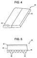
- a radiator or heater tube 40 may be formed from a sheet 42 folded into the shape of tube. A portion 43 of the sheet 42 is shown enlarged in Fig. 5.
- the sheet 42 includes an aluminum alloy waterside liner 44 with textured features 46 rolled therein positioned on one side of an aluminum alloy main body 48 and an aluminum-silicon clad layer 50 positioned on the other side of the main body 48. It has been found that improved heat transfer properties are achieved when the coolant side of heat exchanger tubing includes the textured surface of the present invention.
- the wrought metal products of the present invention are micro-textured to provide substantially higher surface areas than prior heat exchange components with morphologies that aid in increasing turbulence of heat transfer media flowing thereover.
- the textured features 6 are sized sufficiently fine (small) to allow for products fabricated from the textured sheet 2 to be made without concern as to the location of the textured features 6 with respect to the component geometry.
- Micro-textured finstock may include conventional louvers or other embossments and be fabricated in the identical manner and on the same fin machines employed for untextured finstock. As such, the incoming stock used to fabricate a part may be micro-textured without concern for the specific dimensions or part geometries.
- the configurations or patterns of the textured features 6 are also believed to improved other critical product features.
- the textured features 6 improve the directional bending moments of the product, particularly when in the form of parallel ridges as shown in Figs. I and 2, and strengthen the final product. In the case of evaporators where shedding of cooling water is desired, the textured features 6 are believed to improve water management via enhanced capillary action.
Landscapes
- Engineering & Computer Science (AREA)
- Physics & Mathematics (AREA)
- Mechanical Engineering (AREA)
- Thermal Sciences (AREA)
- General Engineering & Computer Science (AREA)
- Geometry (AREA)
- Chemical & Material Sciences (AREA)
- Crystallography & Structural Chemistry (AREA)
- Heat-Exchange Devices With Radiators And Conduit Assemblies (AREA)
- Pressure Welding/Diffusion-Bonding (AREA)
Abstract
Description
- The present invention relates to textured heat transfer surfaces. More particularly, the present invention relates to finstock which is micro-textured to provide increased surface area and increased turbulence of air flowing thereover, and to tubestock, turbulators and the like which are micro-textured to provide increased surface area and increased coolant or refrigerant flow thereover.
- Aluminum and its alloys are particularly useful materials for heat exchangers in a variety of applications including vehicles such as cars, trucks, airplanes, and the like. Aluminum alloys are lighter than steel alloys and thus offer weight advantages in many applications in vehicles. The light weight and excellent heat transfer properties of aluminum alloys make them particularly attractive candidates for use in heat exchangers such as radiators, heaters, evaporators, oil coolers, condensers and the like. These heat exchangers and similar components are typically fabricated from mill finished brazing sheet which may be clad or unclad. Conventional aluminum brazing sheet typically includes two to four roll bonded layers with at least one of the exterior layers being an Aluminum Association (AA) 4xxx series alloy and the other layers being 1xxx, 2xxx, 3xxx, 4xxx, 5xxx, 6xxx, 7xxx or 8xxx series alloy. Mill finished brazing sheet has an inherent roughness of about 0.7 micron root mean squared (RMS) or less. All dimensions referred to hereinafter include the RMS value thereof.
- Aluminum brazing sheet is fabricated into the tubes of heat exchangers and the fins attached thereto. The efficiency of a heat exchanger is significantly affected by many variables including the total surface area of the heat transfer surfaces and the persistence of thermal boundary layers on the heat transfer surfaces. Hence, it is generally desirable to maximize the size of the heat transfer surface area and to turbulate the heat transfer media (coolant, air, refrigerant, etc.) to disrupt the boundary layer and maximize heat transfer.
- For finstock, turbulators and the like, one approach to enhancing turbulation of the heat transfer medium has been to use louvers which are members that are mechanically flared out into the air or coolant stream, and cause re-direction (i.e. turbulation) of the air or coolant. Conventional louvers on finstock are about 0.5-2 millimeters (mm) high and are spaced apart by about 1 mm. The length of a louver typically is about 80-90 percent of the length of a fin. Other types of embossments for heat exchanger fins are disclosed in U. S. Patent Nos. 4,434,846 and 4,984,626, Louvers and other embossments must be incorporated into heat exchanger components with due regard for the geometry of the components. Due to their size and configuration, louvers and embossments can only be used on a limited variety of heat exchanger components and at limited positions on a component.
- More recently, extruded condensor tubing has been provided with small voids in the extrusion profile of the tube which increase the surface area and increase turbulation of the refrigerant flowing therein. Extruded tubing is typically only used for high pressure environments (e.g. 1000 psi) such as in condenscrs because of die relatively high production costs compared to wrought products and the limitations on the alloy types suitable for extrusion.
- Accordingly, a need remains for wrought products having features for enhancing heat transfer which may be used in a variety of heat exchanger components.
- This need is met by the wrought product of the present invention having a micro-textured surface with textured features having dimensions of about 1-50 microns high, preferably about 20-40 microns high, about 1-200 microns wide, preferably about 20-50 microns wide and spaced apart by about 1-50 microns, preferably about 20-50 microns apart. The wrought product may be an aluminum brazing sheet or finstock used in concert with brazing sheet or be formed from stainless steel or copper/brass (Cu/brass). The aluminum may be a monolithic sheet of the AA series 1xxx, 2xxx, 3xxx, 4xxx, 5xxx, 6xxx, 7xxx, or 8xxx or a multilayer composite sheet with each layer being one of the AA series 1xxx, 2xxx, 3xxx, 4xxx, 5xxx, 6xxx, 7xxx, or 8xxx. The textured features are preferably roll textured into the aluminum sheet in a regular pattern of spaced apart cross hatches, spaced apart circles, dimples, parallel lines or combinations thereof. The roll texturing can be done as a finishing step by a material supplier or on a strip as a part of the fabrication practice for a particular component being made (e.g. roll textured while in a fin machine or tube making machine). The wrought sheet is about 25-1500 microns thick.
- The wrought sheet of the present invention may be used to fabricate the 'tubing, fins or turbulators of a heat exchanger such as a radiator, oil cooler, heater, condenser, evaporator or the like. The textured aluminum surface may be present on one or both sides of the fins of a heat exchanger or on the surfaces of the heat exchanger exposed to the coolant and/or refrigerant (e.g. the internal surface of a radiator or heater tube).
- Other features of the present invention will be further described in the following related description of the preferred embodiments which is to be considered together with the accompanying drawings wherein like figures refer to like pans and further wherein
- Fig. 1 is a perspective view of a sheet having textured features made in accordance with the present invention;
- Fig. 2 is a side view of the sheet shown in Fig. 1;
- Fig. 3 is a perspective view of a sheet having another type of textured feature;
- Fig. 4 is a perspective view of a folded tube type of heat exchanger tubing features made in accordance with the present invention; and
- Fig. 5 is an enlarged view of a portion of the tubing shown in Fig. 5.
-
- For purposes of the description hereinafter, the terms "upper", "lower", "right", "left", "vertical", "horizontal", "top", "bottom" and derivatives thereof relate to the invention as it is oriented in the drawing figures. However, it is to be understood that the invention may assume various alternative variations and step sequences, except where expressly specified to the contrary. It is also to be understood that the specific devices and processes illustrated in the attached drawings, and described in the following specification, are simply exemplary embodiments of the invention. Hence, specific dimensions and other physical characteristics related to the embodiments disclosed herein are not to be considered as limiting.
- The present invention includes a wrought product including
textured sheet 2 shown in Fig. 1 and heat exchangers incorporating thesheet 2. In a particularly preferred embodiment, thesheet 2 is produced from mill finished aluminum brazing sheet. Thesheet 2 may be a monolithic sheet of the AA series 1xxx, 2xxx, 3xxx, 4xxx, 5xxx, 6xxx, 7xxx, or 8xxx or a multilayer composite sheet with each layer being one of the AA series 1xxx, 2xxx, 3xxx, 4xxx, 5xxx, 6xxx, 7xxx, or 8xxx. Other aluminum alloys not registered with the Aluminum Association may also used in the present invention. Mill finished aluminum brazing sheet typically has a maximum roughness of about 0.7 micron. The sheet may be produced from other materials such as stainless steel and Cu/brass. - The
sheet 2 has atextured surface 4 on one or both sides thereof in the form ofmicro-textured features 6 extending from amain body 8 of thesheet 2. By the term micro-textured, it is meant texturing which imparts features to the sheet having dimensions larger than the inherent roughness of the sheet yet smaller than conventional embossments in finstock. The texturing may or may not reduce the gauge of thesheet 2. In certain cases, the overall thickness of thesheet 2 is reduced despite the presence of thetextured features 6 extending from themain body 8 of thesheet 2. However, it is also possible for the overall thickness of the sheet 2 (measured from peak to peak on opposing sides of the sheet 2) to increase as a result of creating relatively largetextured features 6. - The
textured features 6 are preferably produced by creating a negative image of a desired pattern onto the surface of a roll and running the mill finished sheet through a set of rolls set at a gap height less than the thickness of the incoming sheet. One or both of the rolls may be patterned depending on whether one or both sides of the wrought product are to be micro-textured. The height of thetextured features 6 is influenced by the amount of reduction of the incoming sheet, determined by a roll separating force (e.g. up to about 9500 psi), taken during the rolling pass. Increases to the roll separating force serves to increase the degree of relief on the surface up to some maximum roll separating force. Beyond this maximum roll separating force, a degradation of the pattern may be observed. As such, there is a critical range of roll separating force that must be established for a particular pattern on a sheet of a particular alloy with particular mechanical properties. The negative pattern on the rolls may be created by use of lasers or by a photo-resist and etch method or any other technique (such as sandblasting or electron discharge machining (EDM)) for reproducibly and precisely removing small and exact bits of the hardened roll into the desired negative pattern. - The
textured features 6 may be present in a variation of configurations. Figs. 1 and 2 show thetextured features 6 as being parallel ridges extending across the width of thesheet 2. Other suitable configurations for thetextured features 6 include spaced apart circles, annuli, grooves, dimples or cross hatches distributed across thetextured surface 4. The spacing between thetextured features 6 may be regular or irregular across thesheet 2. Fig. 3 shows asheet 20 having pyramid-shapedtextured features 26 positioned at regular intervals across one side of thesheet 20. The pattern of thetextured features 6 is determined by the pattern present on the texturing roll. Thetextured features - Mill finished brazing sheet typically has a thickness of about 25-1500 microns with a maximum height of any roughness feature of about 0.7 micron. Referring to Figs. 1 and 2, the thickness T of the
main body 8 of the sheet remains nearly the same as the original thickness of the mill finished sheet less the amount of reduction thereof as result of the roll texturing. The distance H between apeak 10 of thetextured features 6 and themain body 8 of thesheet 2 is preferably about 1-50 microns, more preferably about 20-40 microns. For relatively smooth mill finished sheet, thetextured features 6 may be as small as 1 micron high. For rougher mill finished sheet, the minimum height of thetextured features 6 may be 2-5 microns. The width W of the base of thepeaks 10 is preferably 1-200 microns, more preferably 20-50 microns. The distance D between thepeaks 10 is preferably about 1-50 microns, more preferably 20-50 microns. Eachpeak 10 of atextured feature 6 is shown in Figs. 1 and 2 on onesurface 4 of thesheet 2 as opposing avalley 12 on theother surface 4 of thesheet 2. This is not meant to be limiting as thetextured features 6 on the opposing side of the sheer 2 may have the same or different configuration. - The
sheet 2 may be used to produce a heat exchanger such as a radiator, heater, evaporator, cooler, condenser or the like. Thesheet 2 may be fabricated into the fins of a heat exchanger and/or the tube to which the fins are attached. When thesheet 2 is used as a fin, preferably both sides of thesheet 2 are micro-textured however it is also contemplated that only one side of a fin may include the textured features 6. Thesheet 2 may also be made into a heat exchanger tube. - Heat exchanger tubing may also be micro-textured on the inside surface of the tube (the side in contact with a coolant or refrigerant) or on the exterior surface of the tube to which the fins are attached (the air side or fin side). For example, as shown in Figs. 4 and 5, a radiator or
heater tube 40 may be formed from asheet 42 folded into the shape of tube. Aportion 43 of thesheet 42 is shown enlarged in Fig. 5. Thesheet 42 includes an aluminumalloy waterside liner 44 withtextured features 46 rolled therein positioned on one side of an aluminum alloymain body 48 and an aluminum-silicon cladlayer 50 positioned on the other side of themain body 48. It has been found that improved heat transfer properties are achieved when the coolant side of heat exchanger tubing includes the textured surface of the present invention. - The wrought metal products of the present invention are micro-textured to provide substantially higher surface areas than prior heat exchange components with morphologies that aid in increasing turbulence of heat transfer media flowing thereover. The
textured features 6 are sized sufficiently fine (small) to allow for products fabricated from thetextured sheet 2 to be made without concern as to the location of thetextured features 6 with respect to the component geometry. Micro-textured finstock may include conventional louvers or other embossments and be fabricated in the identical manner and on the same fin machines employed for untextured finstock. As such, the incoming stock used to fabricate a part may be micro-textured without concern for the specific dimensions or part geometries. The configurations or patterns of thetextured features 6 are also believed to improved other critical product features. Thetextured features 6 improve the directional bending moments of the product, particularly when in the form of parallel ridges as shown in Figs. I and 2, and strengthen the final product. In the case of evaporators where shedding of cooling water is desired, thetextured features 6 are believed to improve water management via enhanced capillary action. - It will be readily appreciated by those skilled in the art that modifications may be made to the invention without departing from the concepts disclosed in the foregoing description. Such modifications are to be considered as included within the following claims unless the claims, by their language, expressly state otherwise. Accordingly, the particular embodiments described in detail herein are illustrative only and are not limiting to the scope of the invention which is to be given the full breadth of the appended claims and any and all equivalents thereof.
Claims (24)
- A heat exchanger comprising:a metal tube having a coolant side and a fin side;a metal fin attached to said tube fin side; anda micro-rextured surface positioned on one of said tube coolant side, said tube fin side and said fin, wherein said micro-textured surface has a main surface and plurality of textured features extending from said main surface.
- The heat exchanger of claim 1 wherein said micro-textured surface is present on said coolant side of said tube.
- The heat exchanger of claim 2 wherein said tube is a radiator tube, heater tube or a condenser tube.
- The heat exchanger of claim 1 wherein said micro-textured surface is present on said fin.
- The heat exchanger of claim 1 wherein said textured features are about 1-50 microns in height.
- The heat exchanger of claim 5 wherein said textured features are about 20-40 microns in height.
- The heat exchanger of claim 1 wherein said textured features are spaced apart about 1-50 microns.
- The heat exchanger of claim 1 wherein said textured features are spaced apart about 20-50 microns.
- The heat exchanger of claim 6 wherein the main body in the location of said micro-textured surface is about 25-1500 microns thick.
- The heat exchanger of claim 1 wherein said metal is aluminum, stainless steel or Cu/brass.
- The heat exchanger of claim 10 wherein said metal is an aluminum alloy of the AA series 1xxx, 2xxx, 3xxx, 4xxx, 5xxx, 6xxx, 7xxx, or 8xxx.
- A heat exchange component comprising a metal sheet, said sheet having a micro-textured heat transfer surface, said micro-textured surface having textured features about 1-50 microns in height.
- The component of claim 12 wherein said metal is aluminum, stainless steel or Cu/brass.
- The component of claim 13 whcrein said metal is an aluminum alloy of the AA series 1xxx, 2xxx, 3xxx, 4xxx, 5xxx, 6xxx, 7xxx, or 8xxx.
- The component of claim 14 wherein said micro-textured surface includes a clad layer.
- The component of claim 12 wherein said sheet is roll textured.
- The component of claim 12 wherein said textured features are present in a regular pattern on said textured surface.
- The component of claim 17 wherein said textured features are in the form of spaced apart crosshatches, spaced apart circles or parallel ridges.
- A method of making a heat exchanger component comprising the steps of:providing a mill finished brazing sheet;rolling the sheet between a pair of rolls, at least one of the rolls being textured, to create textured features on at least one side of the sheet thereby increasing the surface area of the textured side of the sheet; andforming the textured sheet into a heat exchanger component, wherein at least one heat transfer surface of the heat exchanger component includes the textured features.
- The method of claim 19 wherein the heat exchanger component is a tube.
- The method of claim 20 wherein the heat transfer surface having the textured features is on an interior surface of the tube.
- The method of claim 19 wherein the heat exchanger component is a fin.
- The method of claim 19 wherein the textured features are about 1-50 microns in height.
- The method of claim 19 wherein the heat exchanger component is a turbulator.
Applications Claiming Priority (2)
| Application Number | Priority Date | Filing Date | Title |
|---|---|---|---|
| US698854 | 1991-05-13 | ||
| US09/698,854 US6644388B1 (en) | 2000-10-27 | 2000-10-27 | Micro-textured heat transfer surfaces |
Publications (2)
| Publication Number | Publication Date |
|---|---|
| EP1202018A2 true EP1202018A2 (en) | 2002-05-02 |
| EP1202018A3 EP1202018A3 (en) | 2004-04-07 |
Family
ID=24806924
Family Applications (1)
| Application Number | Title | Priority Date | Filing Date |
|---|---|---|---|
| EP01125672A Withdrawn EP1202018A3 (en) | 2000-10-27 | 2001-10-26 | Micro-textured heat transfer surfaces |
Country Status (4)
| Country | Link |
|---|---|
| US (2) | US6644388B1 (en) |
| EP (1) | EP1202018A3 (en) |
| JP (1) | JP2002181476A (en) |
| KR (1) | KR20020033062A (en) |
Cited By (14)
| Publication number | Priority date | Publication date | Assignee | Title |
|---|---|---|---|---|
| DE10253457B3 (en) * | 2002-11-16 | 2004-07-22 | Stiebel Eltron Gmbh & Co. Kg | A heat transfer partition with a structured layer with peaks and valleys especially useful for electric heaters for water heating containers or heat exchangers |
| EP1557627A1 (en) * | 2003-12-01 | 2005-07-27 | SPX Cooling Technologies GmbH | Flow duct |
| WO2007042182A1 (en) * | 2005-10-14 | 2007-04-19 | Behr Gmbh & Co. Kg | Heat exchanger |
| EP2086305A2 (en) | 2008-02-01 | 2009-08-05 | Neng Tyi Precision Industries Co., Ltd. | Heat-dissipating element and heat sink having the same |
| DE102008007608A1 (en) * | 2008-02-04 | 2009-08-06 | Behr Gmbh & Co. Kg | Heat exchanger for motor vehicle, has pipes with maeander-shaped moldings and connected directly to block, where pipes are soldered with one another at contact points and are shifted against each other |
| WO2013079665A1 (en) * | 2011-12-02 | 2013-06-06 | Wickeder Westfalenstahl Gmbh | Heat exchanger |
| EP1959220A3 (en) * | 2007-02-14 | 2013-07-24 | Behr GmbH & Co. KG | Heat exchange surface, heat exchanger and method for manufacturing a heat exchange surface |
| US8875780B2 (en) | 2010-01-15 | 2014-11-04 | Rigidized Metals Corporation | Methods of forming enhanced-surface walls for use in apparatae for performing a process, enhanced-surface walls, and apparatae incorporating same |
| WO2015026304A1 (en) * | 2013-08-21 | 2015-02-26 | Ozyegin Universitesi | Nanostructure chemical mechanical polishing induced live nano-structures for lime-scale prevention on heating elements |
| EP3266890A1 (en) * | 2016-07-07 | 2018-01-10 | Hydro Aluminium Rolled Products GmbH | Use of a tape having omnidirectional surface topography for producing a heat exchanger component |
| EP2458316A3 (en) * | 2010-11-24 | 2018-02-21 | Honeywell International Inc. | Entrainment heat sink devices |
| US20200200489A1 (en) * | 2018-12-19 | 2020-06-25 | Mahle International Gmbh | Tube for a heat exchanger and method of making the tube |
| US10807163B2 (en) | 2014-07-14 | 2020-10-20 | Raytheon Technologies Corporation | Additive manufactured surface finish |
| US11969803B2 (en) | 2021-01-28 | 2024-04-30 | Subaru Corporation | Drill and method of producing drilled product |
Families Citing this family (34)
| Publication number | Priority date | Publication date | Assignee | Title |
|---|---|---|---|---|
| JP2003156297A (en) * | 2001-11-16 | 2003-05-30 | Komatsu Ltd | Heat exchanger |
| US7182124B2 (en) * | 2004-08-31 | 2007-02-27 | Egbon Electronics Ltd. | Heat sink structure |
| US7128139B2 (en) * | 2004-10-14 | 2006-10-31 | Nova Chemicals (International) S.A. | External ribbed furnace tubes |
| CN100453955C (en) * | 2005-01-07 | 2009-01-21 | 鸿富锦精密工业(深圳)有限公司 | Heat pipe and manufacturing method thereof |
| US20090044481A1 (en) * | 2005-01-18 | 2009-02-19 | Turek James N | Rebar, beam and mesh highchair |
| FR2890435B1 (en) * | 2005-09-07 | 2007-09-28 | Commissariat Energie Atomique | HEAT EXCHANGER COMPRISING A SUPERCRITICAL CARBON DIOXIDE CIRCUIT |
| US7464700B2 (en) * | 2006-03-03 | 2008-12-16 | Proliance International Inc. | Method for cooling an internal combustion engine having exhaust gas recirculation and charge air cooling |
| US7743821B2 (en) | 2006-07-26 | 2010-06-29 | General Electric Company | Air cooled heat exchanger with enhanced heat transfer coefficient fins |
| US20080078535A1 (en) * | 2006-10-03 | 2008-04-03 | General Electric Company | Heat exchanger tube with enhanced heat transfer co-efficient and related method |
| SE530449C2 (en) * | 2006-10-26 | 2008-06-10 | Ecolean Res & Dev As | Apparatus for filling collapsible packages |
| US7845396B2 (en) * | 2007-07-24 | 2010-12-07 | Asia Vital Components Co., Ltd. | Heat dissipation device with coarse surface capable of intensifying heat transfer |
| US8033325B2 (en) * | 2007-07-24 | 2011-10-11 | Asia Vital Components Co., Ltd. | Heat dissipation apparatus with coarse surface capable of intensifying heat transfer |
| CN100547339C (en) * | 2008-03-12 | 2009-10-07 | 江苏萃隆精密铜管股份有限公司 | A kind of enhanced heat transfer tube and its manufacturing method |
| US8267163B2 (en) * | 2008-03-17 | 2012-09-18 | Visteon Global Technologies, Inc. | Radiator tube dimple pattern |
| DE102008019768A1 (en) * | 2008-04-18 | 2009-10-22 | Hydro Aluminium Deutschland Gmbh | Method of making a tape for packaging |
| US8814954B2 (en) * | 2009-05-08 | 2014-08-26 | Hoowaki, Llc | Method of manufacturing products having a metal surface |
| US8857234B2 (en) * | 2010-01-19 | 2014-10-14 | Board Of Supervisors Of Louisiana State University And Agricultural And Mechanical College | Continuous microscale forming of metal-based microchannels and other microchannel devices |
| US20120111542A1 (en) * | 2010-11-09 | 2012-05-10 | Alcoa Inc. | Coiled heat pipes and methods thereof |
| CN102278904B (en) * | 2011-07-29 | 2013-03-06 | 华北电力大学 | Internal liquid-dividing hood-type condensed heat-exchanging pipe |
| KR102033820B1 (en) | 2011-12-16 | 2019-10-17 | 노벨리스 인코퍼레이티드 | Aluminium fin alloy and method of making the same |
| KR101173842B1 (en) * | 2012-05-21 | 2012-08-16 | 주식회사 한국번디 | L type turn-fin tube and turn-fin type heat exchanger using the l type turn-fin tube |
| JP6016935B2 (en) * | 2012-10-16 | 2016-10-26 | 三菱電機株式会社 | Plate heat exchanger and refrigeration cycle apparatus equipped with the plate heat exchanger |
| CN103851945B (en) * | 2012-12-07 | 2017-05-24 | 诺而达奥托铜业(中山)有限公司 | Internal threaded pipe with rough internal surface |
| JPWO2014184964A1 (en) * | 2013-05-17 | 2017-02-23 | 株式会社日立製作所 | Heat exchanger |
| KR102094529B1 (en) * | 2013-07-23 | 2020-03-30 | 엘지전자 주식회사 | An heat exchanger, a manufacturing mehtod and a manufacturing device the same |
| US20160040947A1 (en) | 2014-08-06 | 2016-02-11 | Novelis Inc. | Aluminum alloy for heat exchanger fins |
| EP3069865B1 (en) * | 2015-03-17 | 2021-10-13 | TI Automotive (Fuldabrück) GmbH | Multilayer motor vehicle supply line |
| EP3390948B1 (en) | 2015-12-16 | 2020-08-19 | Carrier Corporation | Heat transfer tube for heat exchanger |
| CN109328118B (en) * | 2016-06-27 | 2022-09-09 | 哈维全球解决方案有限责任公司 | Microstructured packaging surface for enhanced grip |
| EP3382315B1 (en) * | 2017-03-31 | 2019-11-20 | BSH Hausgeräte GmbH | Laundry drying appliance comprising at least one finned-tube heat exchanger |
| CN108691178B (en) * | 2017-03-31 | 2022-04-08 | Bsh家用电器有限公司 | Household appliances comprising at least one metal part |
| WO2019089736A1 (en) | 2017-10-31 | 2019-05-09 | Arconic Inc. | Improved aluminum alloys, and methods for producing the same |
| US11204204B2 (en) * | 2019-03-08 | 2021-12-21 | Toyota Motor Engineering & Manufacturing North America, Inc. | Acoustic absorber with integrated heat sink |
| US11976856B2 (en) * | 2021-03-19 | 2024-05-07 | Daikin Industries, Ltd. | Shell and plate heat exchanger for water-cooled chiller and water-cooled chiller including the same |
Citations (2)
| Publication number | Priority date | Publication date | Assignee | Title |
|---|---|---|---|---|
| US4434846A (en) | 1981-04-06 | 1984-03-06 | Mcquay Inc. | Patterned heat exchanger fin |
| US4984626A (en) | 1989-11-24 | 1991-01-15 | Carrier Corporation | Embossed vortex generator enhanced plate fin |
Family Cites Families (21)
| Publication number | Priority date | Publication date | Assignee | Title |
|---|---|---|---|---|
| US3457990A (en) * | 1967-07-26 | 1969-07-29 | Union Carbide Corp | Multiple passage heat exchanger utilizing nucleate boiling |
| US3496752A (en) * | 1968-03-08 | 1970-02-24 | Union Carbide Corp | Surface for boiling liquids |
| US3906604A (en) * | 1974-02-01 | 1975-09-23 | Hitachi Cable | Method of forming heat transmissive wall surface |
| US4258783A (en) * | 1977-11-01 | 1981-03-31 | Borg-Warner Corporation | Boiling heat transfer surface, method of preparing same and method of boiling |
| US4182412A (en) * | 1978-01-09 | 1980-01-08 | Uop Inc. | Finned heat transfer tube with porous boiling surface and method for producing same |
| DE3010450A1 (en) * | 1980-03-19 | 1981-09-24 | Kabel- und Metallwerke Gutehoffnungshütte AG, 3000 Hannover | PIPE FOR HEAT EXCHANGER PURPOSES, ESPECIALLY FOR EVAPORATORS |
| ZA873747B (en) * | 1986-05-30 | 1987-11-23 | Alcan International Limited | Prelubricated finstock |
| US4846267A (en) * | 1987-04-01 | 1989-07-11 | The Boc Group, Inc. | Enhanced heat transfer surfaces |
| US6371199B1 (en) * | 1988-02-24 | 2002-04-16 | The Trustees Of The University Of Pennsylvania | Nucleate boiling surfaces for cooling and gas generation |
| JPH0261497A (en) * | 1988-08-25 | 1990-03-01 | Osaka Gas Co Ltd | Heat exchanger |
| US5070937A (en) * | 1991-02-21 | 1991-12-10 | American Standard Inc. | Internally enhanced heat transfer tube |
| JP2802184B2 (en) * | 1991-07-04 | 1998-09-24 | 住友軽金属工業株式会社 | Heat transfer tube for condenser |
| US5249446A (en) * | 1991-07-19 | 1993-10-05 | Aluminum Company Of America | Process for making an aluminum alloy finstock lubricated by a water-microemulsifiable composition |
| US5537851A (en) * | 1993-01-05 | 1996-07-23 | Aluminum Company Of America | Sheet product produced by massive reduction in last stand of cold rolling process |
| KR0132015B1 (en) * | 1993-02-24 | 1998-04-20 | 가나이 쯔도무 | heat transmitter |
| US5377746A (en) * | 1993-04-26 | 1995-01-03 | Fintube Limited Partnership | Texturized fin |
| CN1084876C (en) * | 1994-08-08 | 2002-05-15 | 运载器有限公司 | Heat transfer tube |
| DE19510124A1 (en) * | 1995-03-21 | 1996-09-26 | Km Europa Metal Ag | Exchanger tube for a heat exchanger |
| CA2179448A1 (en) * | 1995-07-12 | 1997-01-13 | Atsuyumi Ishikawa | Heat exchanger for refrigerating cycle |
| IT1283468B1 (en) * | 1996-07-19 | 1998-04-21 | Alcan Alluminio S P A | LAMINATE FOR THE CONSTRUCTION OF HEAT EXCHANGERS AND RELATED PRODUCTION METHOD |
| US6059014A (en) * | 1997-04-21 | 2000-05-09 | Ishikawajima Heavy Industries Co., Ltd. | Casting steel strip |
-
2000
- 2000-10-27 US US09/698,854 patent/US6644388B1/en not_active Expired - Fee Related
-
2001
- 2001-10-25 KR KR1020010065965A patent/KR20020033062A/en not_active Withdrawn
- 2001-10-26 EP EP01125672A patent/EP1202018A3/en not_active Withdrawn
- 2001-10-29 JP JP2001330489A patent/JP2002181476A/en not_active Abandoned
-
2003
- 2003-08-28 US US10/652,754 patent/US6925711B2/en not_active Expired - Fee Related
Patent Citations (2)
| Publication number | Priority date | Publication date | Assignee | Title |
|---|---|---|---|---|
| US4434846A (en) | 1981-04-06 | 1984-03-06 | Mcquay Inc. | Patterned heat exchanger fin |
| US4984626A (en) | 1989-11-24 | 1991-01-15 | Carrier Corporation | Embossed vortex generator enhanced plate fin |
Cited By (16)
| Publication number | Priority date | Publication date | Assignee | Title |
|---|---|---|---|---|
| DE10253457B3 (en) * | 2002-11-16 | 2004-07-22 | Stiebel Eltron Gmbh & Co. Kg | A heat transfer partition with a structured layer with peaks and valleys especially useful for electric heaters for water heating containers or heat exchangers |
| EP1557627A1 (en) * | 2003-12-01 | 2005-07-27 | SPX Cooling Technologies GmbH | Flow duct |
| WO2007042182A1 (en) * | 2005-10-14 | 2007-04-19 | Behr Gmbh & Co. Kg | Heat exchanger |
| EP1959220A3 (en) * | 2007-02-14 | 2013-07-24 | Behr GmbH & Co. KG | Heat exchange surface, heat exchanger and method for manufacturing a heat exchange surface |
| EP2086305A2 (en) | 2008-02-01 | 2009-08-05 | Neng Tyi Precision Industries Co., Ltd. | Heat-dissipating element and heat sink having the same |
| EP2086305A3 (en) * | 2008-02-01 | 2010-04-14 | Neng Tyi Precision Industries Co., Ltd. | Heat-dissipating element and heat sink having the same |
| DE102008007608A1 (en) * | 2008-02-04 | 2009-08-06 | Behr Gmbh & Co. Kg | Heat exchanger for motor vehicle, has pipes with maeander-shaped moldings and connected directly to block, where pipes are soldered with one another at contact points and are shifted against each other |
| US8875780B2 (en) | 2010-01-15 | 2014-11-04 | Rigidized Metals Corporation | Methods of forming enhanced-surface walls for use in apparatae for performing a process, enhanced-surface walls, and apparatae incorporating same |
| EP2458316A3 (en) * | 2010-11-24 | 2018-02-21 | Honeywell International Inc. | Entrainment heat sink devices |
| WO2013079665A1 (en) * | 2011-12-02 | 2013-06-06 | Wickeder Westfalenstahl Gmbh | Heat exchanger |
| WO2015026304A1 (en) * | 2013-08-21 | 2015-02-26 | Ozyegin Universitesi | Nanostructure chemical mechanical polishing induced live nano-structures for lime-scale prevention on heating elements |
| US10807163B2 (en) | 2014-07-14 | 2020-10-20 | Raytheon Technologies Corporation | Additive manufactured surface finish |
| EP2975351B1 (en) * | 2014-07-14 | 2023-11-01 | RTX Corporation | Additive manufactured surface finnish |
| EP3266890A1 (en) * | 2016-07-07 | 2018-01-10 | Hydro Aluminium Rolled Products GmbH | Use of a tape having omnidirectional surface topography for producing a heat exchanger component |
| US20200200489A1 (en) * | 2018-12-19 | 2020-06-25 | Mahle International Gmbh | Tube for a heat exchanger and method of making the tube |
| US11969803B2 (en) | 2021-01-28 | 2024-04-30 | Subaru Corporation | Drill and method of producing drilled product |
Also Published As
| Publication number | Publication date |
|---|---|
| EP1202018A3 (en) | 2004-04-07 |
| US6925711B2 (en) | 2005-08-09 |
| US20040068871A1 (en) | 2004-04-15 |
| JP2002181476A (en) | 2002-06-26 |
| KR20020033062A (en) | 2002-05-04 |
| US6644388B1 (en) | 2003-11-11 |
Similar Documents
| Publication | Publication Date | Title |
|---|---|---|
| US6644388B1 (en) | Micro-textured heat transfer surfaces | |
| US5058266A (en) | Method of making internally finned hollow heat exchanger | |
| JP4077296B2 (en) | Manufacturing method of heat exchange pipe structured on both sides | |
| US5441106A (en) | Heat exchange tubes | |
| US4756362A (en) | Heat exchanger | |
| US6213158B1 (en) | Flat turbulator for a tube and method of making same | |
| CA2347793C (en) | Polyhedral array heat transfer tube | |
| US5682946A (en) | Tube for use in a heat exchanger | |
| RU2289076C2 (en) | Pipes with grooves for reversible usage at heat exchangers | |
| US5388329A (en) | Method of manufacturing a heating exchange tube | |
| EP0591094A1 (en) | Internally ribbed heat transfer tube | |
| EP2917674B1 (en) | Evaporation heat transfer tube with a hollow cavity | |
| JP2008545946A (en) | Plate heat exchanger having an exchange structure forming several channels in the passage | |
| US6687995B1 (en) | Heat exchanger and method for producing a heat exchanger | |
| US20200200489A1 (en) | Tube for a heat exchanger and method of making the tube | |
| WO2018049585A1 (en) | Aluminum alloy composite strip for internal threaded heat exchange tube, and manufacturing method therefor | |
| CN109604367B (en) | Roll bending forming device and method for variable-thickness folding type micro-channel flat tube | |
| JP2011075122A (en) | Aluminum internally-grooved heat transfer tube | |
| KR101441123B1 (en) | Louvered pins for heat exchangers | |
| CA2506936C (en) | Polyhedral array heat transfer tube | |
| CA2591683C (en) | Tube made of a profile rolled metal product and method of producing the same | |
| Webb | Advances in air-cooled heat exchanger technology | |
| CN1147699C (en) | Cooling elements for heat exchangers | |
| ITUD20000150A1 (en) | IMPROVED HIGH EFFICIENCY EVAPORATOR FOR REFRIGERATORS OR FREEZERS | |
| CN220039222U (en) | Fin with transverse texture enhanced heat exchange |
Legal Events
| Date | Code | Title | Description |
|---|---|---|---|
| PUAI | Public reference made under article 153(3) epc to a published international application that has entered the european phase |
Free format text: ORIGINAL CODE: 0009012 |
|
| AK | Designated contracting states |
Kind code of ref document: A2 Designated state(s): AT BE CH CY DE DK ES FI FR GB GR IE IT LI LU MC NL PT SE TR |
|
| AX | Request for extension of the european patent |
Free format text: AL;LT;LV;MK;RO;SI |
|
| PUAL | Search report despatched |
Free format text: ORIGINAL CODE: 0009013 |
|
| AK | Designated contracting states |
Kind code of ref document: A3 Designated state(s): AT BE CH CY DE DK ES FI FR GB GR IE IT LI LU MC NL PT SE TR |
|
| AX | Request for extension of the european patent |
Extension state: AL LT LV MK RO SI |
|
| AKX | Designation fees paid | ||
| REG | Reference to a national code |
Ref country code: DE Ref legal event code: 8566 |
|
| STAA | Information on the status of an ep patent application or granted ep patent |
Free format text: STATUS: THE APPLICATION IS DEEMED TO BE WITHDRAWN |
|
| 18D | Application deemed to be withdrawn |
Effective date: 20041008 |