EP1201973A1 - Vessel with a lid - Google Patents
Vessel with a lid Download PDFInfo
- Publication number
- EP1201973A1 EP1201973A1 EP01203959A EP01203959A EP1201973A1 EP 1201973 A1 EP1201973 A1 EP 1201973A1 EP 01203959 A EP01203959 A EP 01203959A EP 01203959 A EP01203959 A EP 01203959A EP 1201973 A1 EP1201973 A1 EP 1201973A1
- Authority
- EP
- European Patent Office
- Prior art keywords
- vessel
- lid
- opening
- cams
- situated
- Prior art date
- Legal status (The legal status is an assumption and is not a legal conclusion. Google has not performed a legal analysis and makes no representation as to the accuracy of the status listed.)
- Granted
Links
- 238000007789 sealing Methods 0.000 claims description 9
- 239000000203 mixture Substances 0.000 description 4
- 239000004568 cement Substances 0.000 description 2
- 239000004576 sand Substances 0.000 description 2
- 230000000712 assembly Effects 0.000 description 1
- 238000000429 assembly Methods 0.000 description 1
- 238000010276 construction Methods 0.000 description 1
- 230000008878 coupling Effects 0.000 description 1
- 238000010168 coupling process Methods 0.000 description 1
- 238000005859 coupling reaction Methods 0.000 description 1
- 230000000284 resting effect Effects 0.000 description 1
- 239000000126 substance Substances 0.000 description 1
- 238000013022 venting Methods 0.000 description 1
- XLYOFNOQVPJJNP-UHFFFAOYSA-N water Substances O XLYOFNOQVPJJNP-UHFFFAOYSA-N 0.000 description 1
Images

Classifications
-
- B—PERFORMING OPERATIONS; TRANSPORTING
- B65—CONVEYING; PACKING; STORING; HANDLING THIN OR FILAMENTARY MATERIAL
- B65D—CONTAINERS FOR STORAGE OR TRANSPORT OF ARTICLES OR MATERIALS, e.g. BAGS, BARRELS, BOTTLES, BOXES, CANS, CARTONS, CRATES, DRUMS, JARS, TANKS, HOPPERS, FORWARDING CONTAINERS; ACCESSORIES, CLOSURES, OR FITTINGS THEREFOR; PACKAGING ELEMENTS; PACKAGES
- B65D90/00—Component parts, details or accessories for large containers
- B65D90/10—Manholes; Inspection openings; Covers therefor
-
- F—MECHANICAL ENGINEERING; LIGHTING; HEATING; WEAPONS; BLASTING
- F16—ENGINEERING ELEMENTS AND UNITS; GENERAL MEASURES FOR PRODUCING AND MAINTAINING EFFECTIVE FUNCTIONING OF MACHINES OR INSTALLATIONS; THERMAL INSULATION IN GENERAL
- F16J—PISTONS; CYLINDERS; SEALINGS
- F16J13/00—Covers or similar closure members for pressure vessels in general
- F16J13/02—Detachable closure members; Means for tightening closures
- F16J13/06—Detachable closure members; Means for tightening closures attached only by clamps along the circumference
-
- F—MECHANICAL ENGINEERING; LIGHTING; HEATING; WEAPONS; BLASTING
- F16—ENGINEERING ELEMENTS AND UNITS; GENERAL MEASURES FOR PRODUCING AND MAINTAINING EFFECTIVE FUNCTIONING OF MACHINES OR INSTALLATIONS; THERMAL INSULATION IN GENERAL
- F16J—PISTONS; CYLINDERS; SEALINGS
- F16J13/00—Covers or similar closure members for pressure vessels in general
- F16J13/22—Covers or similar closure members for pressure vessels in general with movement parallel to the plane of the opening
-
- B—PERFORMING OPERATIONS; TRANSPORTING
- B65—CONVEYING; PACKING; STORING; HANDLING THIN OR FILAMENTARY MATERIAL
- B65D—CONTAINERS FOR STORAGE OR TRANSPORT OF ARTICLES OR MATERIALS, e.g. BAGS, BARRELS, BOTTLES, BOXES, CANS, CARTONS, CRATES, DRUMS, JARS, TANKS, HOPPERS, FORWARDING CONTAINERS; ACCESSORIES, CLOSURES, OR FITTINGS THEREFOR; PACKAGING ELEMENTS; PACKAGES
- B65D2590/00—Component parts, details or accessories for large containers
- B65D2590/54—Gates or closures
- B65D2590/542—Gates or closures special sealing means or means for improving sealing
Definitions
- the present invention concerns a vessel with a lid, which vessel is provided with an opening extending in a flat surface and which can be sealed by the lid, whereby this lid can rotate in relation to the vessel, around an axis directed perpendicular to the surface of the opening and situated next to the opening, between a position in which it is rotated shut and in which it is situated opposite to the opening and an open position in which it is situated next to the opening.
- the invention in particular concerns a pressure vessel with a lid, whereby the vessel can be put under pressure.
- the lid still has to provide for a good sealing.
- Such pressure vessels with a lid are for example part of a mixer plant, whereby a mixing element is then mounted inside the vessel, forming a mixing vessel.
- Such mixer plants are used to produce a mixture on the basis of cement and sand, and possibly other substances, whereby compressed air is usually supplied to the mixing vessel to carry the mixture to its ultimate destination via flexible pipes.
- the lid can hermetically seal the opening through which the components are provided in the mixing vessel.
- Mixer plants are known which are provided with loose sealing lids, which can be attached to the mixing vessel for example by means of a bayonet coupling or by means of clamps. As these lids are loose, they can get lost or can be easily damaged.
- the lid is situated inside the mixing vessel.
- the lid is pressed against the edge of the filling opening by the pressure which, after the mixing vessel has been filled, is built up in the latter thanks to the supply of compressed air.
- the vessel is not immediately hermetically sealed, so that while the pressure is being built up, cement, sand and such can temporarily escape between the lid and the mixing vessel or the filling pipe thereof, until the lid is pressed with sufficient pressure against the mixing vessel.
- the mixing element must be kept at a certain distance from the filling opening for safety reasons. This implies that, because of the space occupied by a lid which is situated on the inside in relation to the filling opening, this filling opening must be situated higher than usual, so that it is more difficult to shovel in the components to be mixed.
- Vessels according to the first paragraph with a rotating lid at the outside of the vessel are also known.
- the problem with these vessels is to lock the lid in closed position in a safe way when pressure inside the vessel is above atmospheric pressure.
- Vessels are known wherein cams are used for this purpose.
- Such vessel is described in US-A-6.095.365.
- Cam members rotate about cam shafts on adjusting bolts screwed in nuts which in turn rotate about pins in cam support brackets fixed to the vessel.
- Cam shafts and pins extend horizontally, parallel to tangents of the round opening to be closed.
- the nuts are successively rotated about the pins to raise the nuts and bolts to a vertical position, with the bolts each disposed in a slot of a bearing plate fixed to the lid, after which the cam members are rotated about the cam shafts.
- these movements are made in the inverse order.
- cam assemblies are of a rather complicated structure and locking is time consuming.
- the locking of unlocking requires for each cam assembly two different rotations, one of the nut and bolt and one of the cam. This makes automation of the locking difficult and costly.
- the invention aims a vessel with a rotating lid at the outside of the vessel, which does not have the above-mentioned disadvantages and which is of a relatively simple construction and which can be hermetically sealed in a fast and easy manner, whereby automation of the locking of the lid is relatively easy.
- this aim is reached in a vessel with lid, which vessel is provided with an opening extending in a flat surface and which can be sealed by the lid, whereby this lid can rotate in relation to the vessel, around an axis directed perpendicular to the surface of the opening and situated next to the opening, between a position in which it is rotated shut and in which it is situated opposite to the opening and an open position in which it is situated next to the opening, whereby the lid is situated on the outside of the opening in relation to the vessel, and means are provided on the vessel to bring the lid from the position in which it is rotated shut in the closed position and to lock it, said means comprising at least two cams which can rotate in relation to the vessel, by the characterised that each of the cams is rotating in a support which is stationary mounted on the vessel, the stationary supports being situated and shaped such that the lid can be rotated shut between the cams and the vessel.
- the cams are not mounted on pivoting nuts but directly on stationary supports. Only a single rotation of the cams is required to lock or unlock the lid.
- the locking means contain preferably two cams, whereby one cam is situated near the axis of rotation of the lid, and the other one is situated diametrically opposed to it.
- the locking means preferably contain hydraulic or pneumatic means for rotating the cams.
- this movement can be easily be performed by hydraulic or pneumatic means.
- the cams are rotating around a geometrical axis extending transversely with respect to the nearest edge of the opening, this is in radial direction with respect to the opening when this opening is round.
- Each cam may be fixed on a shaft which is rotating in a support.
- a special application of the invention regards mixer plants, whereby the vessel is a mixing vessel and the opening is a filling opening.
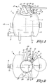
- the mixer plant represented in figures 1 to 7 mainly comprises a mixing vessel 1 provided with a round filling opening 2 at the top, a lid 3 to seal this filling opening 2 and a mixing element 4 erected in the mixing vessel 1, consisting for example of a shaft and blades or mixing arms provided onto it, driven by a motor which is not represented in the figures.
- the mixing vessel 1 consists of a round tub 5 with spherical far ends, resting horizontally with its longitudinal axis in supports 6 standing for example on a frame, and of a round filling pipe 7 which is connected onto the top side of the tub 5.
- the top far end of this filling pipe 7 is flat and open, and it forms the above-mentioned filling opening 2 which thus extends in a flat plane.
- the filling pipe 7 Onto the filling pipe 7 are connected one or several, in the given example two, mouthpieces 8. One of them is used to insert water, followed by compressed air, in the filling pipe 7 and thus in the mixing vessel 1, the other for the venting after the mixing.
- the tub 5 At the bottom, the tub 5 is provided with an outlet 9 for the mixture. Into this outlet 9, onto which can be connected a drain hose, can also flow a mouthpiece 10 to possibly supply extra compressed air, especially for the conveyance through the hose.
- the lid 3 is hinge-mounted around a shaft 12 with a part 11 protruding outside its perimeter which, as is represented in detail in figure 6, is fixed to a support 13 which is welded onto the outside of the filling pipe 7.
- Said shaft 12 is perpendicular to the surface of the filling opening 2.
- the lid 3 can shift in the vertical height over the shaft 12.
- the lid 3 is fixed to this end on a bush 15 which envelops the shaft 12 in a revolving manner by means of a bolt 14.
- this bush 15 is pushed up by a spring 17 which surrounds the shaft 12 between the support 13 and the bush 15.
- a collar 18 at the top far end of the shaft 12 restricts the upward movement of the bush 15.
- the round lid 3 is provided with a concentric groove 19 whose average diameter coincides with the inner diameter of the open end of the filling pipe 7.
- These means 21 contain two cams 22 which are rotating about an axis extending transversally to the nearest edge of the opening 2, this is practically radial with respect to the filling opening 2 when this opening is round as in the given example.
- the cams 22 are fixed to shafts 23, which are bearing-mounted in supports 24, for example blocks as shown in the figures.
- the supports 24 are fixed to the vessel 1, for example welded onto the outside of the filling pipe 7 and which are thus stationary with respect to the vessel 1.
- each of the cams 22 can also be provided on a cam disc, which is then fixed on a shaft 23.
- the supports 24 are provided with the necessary recesses 27 on their side which is turned towards the filling opening 2, so as not to hinder the lid 3 while it is rotated shut and locked. Shape and position of the supports 24 is thus such that the lid 3 can be rotated shut and thereby be inserted between the cams 22 and the filling pipe 7 of the vessel 1.
- the lid 3 is closed and locked as follows.
- Figures 1 and 2 represent the lid 3 when rotated into the open position.
- the cams 22 are hereby directed almost horizontally and the handles 25 are practically situated at an angle of 45° in relation to the vertical axis.
- the lid 3 is rotated to above the filling opening 2, i.e. in the shut position represented in figure 3.
- the lid 3 is situated in its highest position on the shaft 12, so that the sealing ring 20 is not or barely situated against the farthest edge of the filling pipe 7.
- the cams 22 thereby rotate towards the bottom, first until they are directed vertically down, whereby they thus push the lid 3 down against the action of the spring 17, so that the sealing ring 20 is strongly pushed against the edge of the filling pipe 7.
- the handles 25 are rotated up against their stops 26, which are situated such that the cams 22 rotate somewhat further during this rotation than the downward directed position, into the position which is clearly shown in figure 7.
- the pressure on the sealing ring 20 diminishes somewhat during the rotation past the downward directed position, but it is still sufficient to ensure a hermetic sealing.
- these cams 22 would be rotated back due to the upward pressure exerted on the cams 22 by the lid 3 as a result of the pressure in the mixing vessel 1.
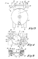
- Figures 4 to 7 represent the lid 3 in the closed position when locked.
- the cams 22 do not necessarily have to be rotated manually, as described above. They can also be rotated in a mechanical manner, for example by means of a motor, or pneumatically or hydraulically.
- Figure 8 represents a variant whereby each of the handles 25 is fixed to a hydraulic or pneumatic cylinder 28 which may bring about the rotation of the handles 25 up against the stop 26 and vice versa.
- sealing ring 20 is preferably provided in the lid 3, the latter can also be provided in the edge of the filling pipe 7, according to a variant, provided that it is sufficiently thick.
- the vessel must not necessarily be a mixing vessel, nor must the opening be a filling opening.
- the invention can also be applied to other vessels, in particular pressure vessels, which are provided with an opening sealed by a lid.
Landscapes
- Engineering & Computer Science (AREA)
- General Engineering & Computer Science (AREA)
- Mechanical Engineering (AREA)
- Closures For Containers (AREA)
- Pressure Vessels And Lids Thereof (AREA)
- Mixers With Rotating Receptacles And Mixers With Vibration Mechanisms (AREA)
Abstract
Description
- The present invention concerns a vessel with a lid, which vessel is provided with an opening extending in a flat surface and which can be sealed by the lid, whereby this lid can rotate in relation to the vessel, around an axis directed perpendicular to the surface of the opening and situated next to the opening, between a position in which it is rotated shut and in which it is situated opposite to the opening and an open position in which it is situated next to the opening.
- The invention in particular concerns a pressure vessel with a lid, whereby the vessel can be put under pressure. When this is the case, the lid still has to provide for a good sealing.
- Such pressure vessels with a lid are for example part of a mixer plant, whereby a mixing element is then mounted inside the vessel, forming a mixing vessel.
- Such mixer plants are used to produce a mixture on the basis of cement and sand, and possibly other substances, whereby compressed air is usually supplied to the mixing vessel to carry the mixture to its ultimate destination via flexible pipes.
- It is very important thereby, that the lid can hermetically seal the opening through which the components are provided in the mixing vessel.
- Mixer plants are known which are provided with loose sealing lids, which can be attached to the mixing vessel for example by means of a bayonet coupling or by means of clamps. As these lids are loose, they can get lost or can be easily damaged.
- These disadvantages are not found in a mixer plant with a vessel having a lid according to the first paragraph, whereby the lid is fixed to the vessel such that it can rotate.
- With some known mixer plants of this type, however, the lid is situated inside the mixing vessel.
- However, this restricts the size of the filling opening since, besides this filling opening, inside the mixing vessel or for example the upstand or standing filling pipe thereof in which the filling opening is usually situated, there must be room for the lid in its open position.
- The lid is pressed against the edge of the filling opening by the pressure which, after the mixing vessel has been filled, is built up in the latter thanks to the supply of compressed air. However, the vessel is not immediately hermetically sealed, so that while the pressure is being built up, cement, sand and such can temporarily escape between the lid and the mixing vessel or the filling pipe thereof, until the lid is pressed with sufficient pressure against the mixing vessel.
- According to the regulations, the mixing element must be kept at a certain distance from the filling opening for safety reasons. This implies that, because of the space occupied by a lid which is situated on the inside in relation to the filling opening, this filling opening must be situated higher than usual, so that it is more difficult to shovel in the components to be mixed.
- Vessels according to the first paragraph with a rotating lid at the outside of the vessel are also known. The problem with these vessels is to lock the lid in closed position in a safe way when pressure inside the vessel is above atmospheric pressure. Vessels are known wherein cams are used for this purpose.
- Such vessel is described in US-A-6.095.365. Cam members rotate about cam shafts on adjusting bolts screwed in nuts which in turn rotate about pins in cam support brackets fixed to the vessel. Cam shafts and pins extend horizontally, parallel to tangents of the round opening to be closed. In order to close and lock the lid when it is rotated shut, the nuts are successively rotated about the pins to raise the nuts and bolts to a vertical position, with the bolts each disposed in a slot of a bearing plate fixed to the lid, after which the cam members are rotated about the cam shafts. For unlocking and opening the lid, these movements are made in the inverse order.
- The cam assemblies are of a rather complicated structure and locking is time consuming. The locking of unlocking requires for each cam assembly two different rotations, one of the nut and bolt and one of the cam. This makes automation of the locking difficult and costly.
- Also, the invention aims a vessel with a rotating lid at the outside of the vessel, which does not have the above-mentioned disadvantages and which is of a relatively simple construction and which can be hermetically sealed in a fast and easy manner, whereby automation of the locking of the lid is relatively easy.
- According to the invention, this aim is reached in a vessel with lid, which vessel is provided with an opening extending in a flat surface and which can be sealed by the lid, whereby this lid can rotate in relation to the vessel, around an axis directed perpendicular to the surface of the opening and situated next to the opening, between a position in which it is rotated shut and in which it is situated opposite to the opening and an open position in which it is situated next to the opening, whereby the lid is situated on the outside of the opening in relation to the vessel, and means are provided on the vessel to bring the lid from the position in which it is rotated shut in the closed position and to lock it, said means comprising at least two cams which can rotate in relation to the vessel, by the characterised that each of the cams is rotating in a support which is stationary mounted on the vessel, the stationary supports being situated and shaped such that the lid can be rotated shut between the cams and the vessel.
- The cams are not mounted on pivoting nuts but directly on stationary supports. Only a single rotation of the cams is required to lock or unlock the lid.
- The locking means contain preferably two cams, whereby one cam is situated near the axis of rotation of the lid, and the other one is situated diametrically opposed to it.
- The locking means preferably contain hydraulic or pneumatic means for rotating the cams.
- As only one movement, this is a rotation of each cam has to be performed, this movement can be easily be performed by hydraulic or pneumatic means.
- In a particular embodiment, the cams are rotating around a geometrical axis extending transversely with respect to the nearest edge of the opening, this is in radial direction with respect to the opening when this opening is round.
- Each cam may be fixed on a shaft which is rotating in a support.
- A special application of the invention regards mixer plants, whereby the vessel is a mixing vessel and the opening is a filling opening.
- In order to better explain the characteristics of the invention, the following preferred embodiment of a vessel with a lid according to the invention is described as an example only without being limiting in any way, with reference to the accompanying drawings, in which:
- Figure 1 represents a front view of a mixer plant provided with a vessel with a lid according to the invention, whereby the lid is rotated open;
- Figure 2 represents a top view of the mixer plant of figure 1;
- Figure 3 represents a side view according to arrow F3 in figure 1, but with the lid rotated shut;
- Figure 4 represents a part of a top view analogous to that in figure 3, but with the lid closed and locked;
- Figure 5 represents a section according to line V-V in figure 4;
- Figure 6 represents a section according to line VI-VI in figure 4, to a larger scale;
- Figure 7 represents a view according to arrow F7 in figure 4, drawn to a larger scale;
- Figure 8 represents a view of a handle for locking the lid, but with reference to another embodiment of the invention.
-
- The mixer plant represented in figures 1 to 7 mainly comprises a mixing vessel 1 provided with a
round filling opening 2 at the top, alid 3 to seal this fillingopening 2 and amixing element 4 erected in the mixing vessel 1, consisting for example of a shaft and blades or mixing arms provided onto it, driven by a motor which is not represented in the figures. - The mixing vessel 1 consists of a
round tub 5 with spherical far ends, resting horizontally with its longitudinal axis insupports 6 standing for example on a frame, and of around filling pipe 7 which is connected onto the top side of thetub 5. The top far end of thisfilling pipe 7 is flat and open, and it forms the above-mentionedfilling opening 2 which thus extends in a flat plane. - Onto the
filling pipe 7 are connected one or several, in the given example two,mouthpieces 8. One of them is used to insert water, followed by compressed air, in thefilling pipe 7 and thus in the mixing vessel 1, the other for the venting after the mixing. At the bottom, thetub 5 is provided with anoutlet 9 for the mixture. Into thisoutlet 9, onto which can be connected a drain hose, can also flow amouthpiece 10 to possibly supply extra compressed air, especially for the conveyance through the hose. - The
lid 3 is hinge-mounted around ashaft 12 with apart 11 protruding outside its perimeter which, as is represented in detail in figure 6, is fixed to asupport 13 which is welded onto the outside of thefilling pipe 7. Saidshaft 12 is perpendicular to the surface of the filling opening 2. - The
lid 3 can shift in the vertical height over theshaft 12. - As is represented in detail in figure 6, the
lid 3 is fixed to this end on abush 15 which envelops theshaft 12 in a revolving manner by means of abolt 14. - With the help of a ball bearing 16, this
bush 15 is pushed up by aspring 17 which surrounds theshaft 12 between thesupport 13 and thebush 15. Acollar 18 at the top far end of theshaft 12 restricts the upward movement of thebush 15. - At a short distance from its outer perimeter, the
round lid 3 is provided with aconcentric groove 19 whose average diameter coincides with the inner diameter of the open end of thefilling pipe 7. - In this
groove 19 is clamped arubber sealing ring 20. - On the mixing vessel 1, in particular on the
filling pipe 7, are provided means 21 to lock thelid 3. - These means 21 contain two
cams 22 which are rotating about an axis extending transversally to the nearest edge of theopening 2, this is practically radial with respect to thefilling opening 2 when this opening is round as in the given example. - The
cams 22 are fixed toshafts 23, which are bearing-mounted insupports 24, for example blocks as shown in the figures. Thesupports 24 are fixed to the vessel 1, for example welded onto the outside of thefilling pipe 7 and which are thus stationary with respect to the vessel 1. Instead of being fixed directly on itsshaft 23, each of thecams 22 can also be provided on a cam disc, which is then fixed on ashaft 23. - Either of the two
supports 24 is erected immediately next to thesupport 13, while the other is diametrically opposed to the first one. - On the outside of the
supports 24,longitudinal handles 25 are fixed on theshafts 23. The rotation of thesehandles 25 is restricted by astop 26. - The supports 24 are provided with the necessary recesses 27 on their side which is turned towards the filling
opening 2, so as not to hinder thelid 3 while it is rotated shut and locked. Shape and position of thesupports 24 is thus such that thelid 3 can be rotated shut and thereby be inserted between thecams 22 and the fillingpipe 7 of the vessel 1. - The
lid 3 is closed and locked as follows. - Figures 1 and 2 represent the
lid 3 when rotated into the open position. Thecams 22 are hereby directed almost horizontally and thehandles 25 are practically situated at an angle of 45° in relation to the vertical axis. - After the components for the mixture to be produced have been introduced via the filling
opening 2, thelid 3 is rotated to above the fillingopening 2, i.e. in the shut position represented in figure 3. - Because of the
spring 17, thelid 3 is situated in its highest position on theshaft 12, so that the sealingring 20 is not or barely situated against the farthest edge of the fillingpipe 7. - By placing the
shaft 12 so that a theoretical plane through the middle of saidshaft 12 and the middle of the fillingopening 2 forms an angle of about 45° in relation to the longitudinal direction of the mixing vessel 1, it can be obtained that, for the given model of the mixing vessel 1, thelid 3 does not protrude sideways outside the mixing vessel 1 during the above-mentioned rotation. It is clear that, for example with other models of the mixing vessel 1, other positions of theshaft 12 are possible. - In order to bring the
lid 3 in the closed position and to lock it, the twoshafts 23 are rotated over somewhat more than 45° by means of thehandles 25. - The
cams 22 thereby rotate towards the bottom, first until they are directed vertically down, whereby they thus push thelid 3 down against the action of thespring 17, so that the sealingring 20 is strongly pushed against the edge of the fillingpipe 7. - The
handles 25 are rotated up against theirstops 26, which are situated such that thecams 22 rotate somewhat further during this rotation than the downward directed position, into the position which is clearly shown in figure 7. The pressure on the sealingring 20 diminishes somewhat during the rotation past the downward directed position, but it is still sufficient to ensure a hermetic sealing. Thus is avoided that thesecams 22 would be rotated back due to the upward pressure exerted on thecams 22 by thelid 3 as a result of the pressure in the mixing vessel 1. - Figures 4 to 7 represent the
lid 3 in the closed position when locked. - After the mixing and the emptying of the mixing vessel 1, first the
handles 25, and consequently also theshafts 23 with thecams 22, are rotated back into their initial position, so that, under the influence of thespring 17, thelid 3 is pushed up a little, from the closed position into the position in which it is rotated shut, after which it can be easily rotated sideways into the open position. - The
cams 22 do not necessarily have to be rotated manually, as described above. They can also be rotated in a mechanical manner, for example by means of a motor, or pneumatically or hydraulically. - Figure 8 represents a variant whereby each of the
handles 25 is fixed to a hydraulic or pneumatic cylinder 28 which may bring about the rotation of thehandles 25 up against thestop 26 and vice versa. - It is clear that the
stop 26 for the restriction of the rotation of acam 22 must not necessarily work in conjunction with thehandle 25. Thisstop 26 could also work directly in conjunction with thecam 22. - Although the sealing
ring 20 is preferably provided in thelid 3, the latter can also be provided in the edge of the fillingpipe 7, according to a variant, provided that it is sufficiently thick. - Although a mixer plant with a mixing vessel 1 and a
lid 3 are described above, the vessel must not necessarily be a mixing vessel, nor must the opening be a filling opening. The invention can also be applied to other vessels, in particular pressure vessels, which are provided with an opening sealed by a lid. - The invention is by no means limited to the above-described embodiment represented in the accompanying drawings; on the contrary, such a vessel with a lid can be made in all sorts.of variants while still remaining within the scope of the invention.
Claims (16)
- Vessel with a lid, which vessel (1) is provided with an opening (2) extending in a flat surface and which can be sealed by the lid (3), whereby this lid (3) can rotate in relation to the vessel (1), around an axis directed perpendicular to the surface of the opening (2) and situated next to the opening (2), between a position in which it is rotated shut and in which it is situated opposite to the opening (2) and an open position in which it is situated next to the opening (2), whereby the lid (3) is situated on the outside of the opening (2) in relation to the vessel (1), and means (21) are provided on the vessel (1) to bring the lid (3) from the position in which it is rotated shut in the closed position and to lock it, said means (21) comprising at least two cams (22) which can rotate in relation to the vessel (1), characterised in that each of the cams (22) is rotating in a support (24) which is stationary mounted on the vessel (1), the stationary supports (24) being situated and shaped such that the lid (3) can be rotated shut between the cams (22) and the vessel (1).
- Vessel with a lid according to claim 1, characterised in that the locking means (21) contain two cams (22), whereby one cam is situated near the axis of rotation of the lid (3), and the other one is situated diametrically opposed to it.
- Vessel with a lid according to claim 1 or 2, characterised in that the locking means (21) contain hydraulic or pneumatic means for rotating the cams (22).
- Vessel with a lid according to any one of claims 1 to 3, characterised in that the cams (22) are rotating around a geometrical axis extending transversely with respect to the nearest edge of the opening (2), this is in the radial direction with respect to the opening (2) when this opening is round.
- Vessel according to any one of the preceding claims, characterised in that each cam (22) is fixed on a shaft (23) which is rotating in a support (24).
- Vessel with a lid according to claim 5, characterised in that, on the outside of the support (24), a handle (25) is fixed on the shaft (23).
- Vessel with a lid according to any of the preceding claims, characterised in that a cam (22) can be rotated to somewhat past the position in which the lid (3) is pushed maximally against the edge of the opening (2), which position is the locked position.
- Vessel with a lid according to claim 7, characterised in that the locking means (21) contain stops (26) which are fixed in relation to the vessel (1), and which restrict the rotation of the cam (22) in the closing and locking direction of the lid (3) directly or indirectly to the locked position.
- Vessel with a lid according to any of the preceding claims, characterised in that the vessel (1) contains a tub (5), and in that a plane through the axis of rotation of the lid (3) and the middle of the opening (2) forms an angle of about 45° in relation to the axis of the tub (5).
- Vessel with a lid according to any of the preceding claims, characterised in that the lid (3) is provided with a groove (19) at its bottom side in which is provided a sealing ring (20).
- Vessel with a lid according to any of the preceding claims, characterised in that the lid (3) can rotate around a shaft (12) standing on a support (13) which is fixed in relation to the vessel (1), whereby the lid (3) can be shifted in the height over this shaft (12).
- Vessel with a lid according to claim 11, characterised in that a spring (17) surrounds the shaft (12) and pushes the lid (3) away from the vessel (1).
- Vessel with a lid according claim 12, characterised in that the lid (3) is fixed on a bush (15) which rests on the spring (17) by means of a bearing (16), which spring surrounds the shaft (12) between said bush (15) and the support (13).
- Vessel with a lid according to any of the preceding claims, characterised in that the vessel (1) contains a pipe (7) and in that the opening (2) is formed by the open end of the pipe (7).
- Vessel with a lid according to any of the preceding claims, characterised in that it is a pressure vessel whose internal pressure can be set higher than the ambient pressure.
- Vessel with a lid according to any of the preceding claims, characterised in that it is a mixing vessel (1) of a mixer plant, and in that the opening is the filling opening (2) of this mixing vessel (1).
Applications Claiming Priority (2)
| Application Number | Priority Date | Filing Date | Title |
|---|---|---|---|
| BE200000689 | 2000-10-27 | ||
| BE2000/0689A BE1013815A3 (en) | 2000-10-27 | 2000-10-27 | Barrel with lid |
Publications (2)
| Publication Number | Publication Date |
|---|---|
| EP1201973A1 true EP1201973A1 (en) | 2002-05-02 |
| EP1201973B1 EP1201973B1 (en) | 2003-07-02 |
Family
ID=3896736
Family Applications (1)
| Application Number | Title | Priority Date | Filing Date |
|---|---|---|---|
| EP01203959A Expired - Lifetime EP1201973B1 (en) | 2000-10-27 | 2001-10-16 | Vessel with a lid |
Country Status (4)
| Country | Link |
|---|---|
| EP (1) | EP1201973B1 (en) |
| AT (1) | ATE244371T1 (en) |
| BE (1) | BE1013815A3 (en) |
| DE (1) | DE60100427T2 (en) |
Cited By (1)
| Publication number | Priority date | Publication date | Assignee | Title |
|---|---|---|---|---|
| CN120942713A (en) * | 2025-10-16 | 2025-11-14 | 山西建投矿建集团有限公司 | A smart mining equipment for mass production and multi-functional sensor installation |
Families Citing this family (1)
| Publication number | Priority date | Publication date | Assignee | Title |
|---|---|---|---|---|
| CN110953343B (en) * | 2019-12-23 | 2021-08-10 | 青岛科技大学 | Autoclave automatic switching device and use method |
Citations (5)
| Publication number | Priority date | Publication date | Assignee | Title |
|---|---|---|---|---|
| GB1071010A (en) * | 1965-01-12 | 1967-06-07 | Masch Und App Bau Dietikon Ag | Improvements in or relating to a locking mechanism, in particular for autoclaves |
| US4157146A (en) * | 1978-09-25 | 1979-06-05 | Svenson Bert N | Safety clamping system for pressure vessel closures and the like |
| DE3641328A1 (en) * | 1986-12-03 | 1988-06-16 | Mann & Hummel Filter | Device for mixing a granular or pulverulent main material and at least one additive |
| EP0456911A1 (en) * | 1988-11-28 | 1991-11-21 | Bremat B.V. | Mixer-transport apparatus for floor mortar and the like |
| US6095365A (en) | 1998-08-24 | 2000-08-01 | The Heil Company | Pivoting hatch cover assembly |
-
2000
- 2000-10-27 BE BE2000/0689A patent/BE1013815A3/en not_active IP Right Cessation
-
2001
- 2001-10-16 EP EP01203959A patent/EP1201973B1/en not_active Expired - Lifetime
- 2001-10-16 AT AT01203959T patent/ATE244371T1/en not_active IP Right Cessation
- 2001-10-16 DE DE60100427T patent/DE60100427T2/en not_active Expired - Fee Related
Patent Citations (5)
| Publication number | Priority date | Publication date | Assignee | Title |
|---|---|---|---|---|
| GB1071010A (en) * | 1965-01-12 | 1967-06-07 | Masch Und App Bau Dietikon Ag | Improvements in or relating to a locking mechanism, in particular for autoclaves |
| US4157146A (en) * | 1978-09-25 | 1979-06-05 | Svenson Bert N | Safety clamping system for pressure vessel closures and the like |
| DE3641328A1 (en) * | 1986-12-03 | 1988-06-16 | Mann & Hummel Filter | Device for mixing a granular or pulverulent main material and at least one additive |
| EP0456911A1 (en) * | 1988-11-28 | 1991-11-21 | Bremat B.V. | Mixer-transport apparatus for floor mortar and the like |
| US6095365A (en) | 1998-08-24 | 2000-08-01 | The Heil Company | Pivoting hatch cover assembly |
Cited By (1)
| Publication number | Priority date | Publication date | Assignee | Title |
|---|---|---|---|---|
| CN120942713A (en) * | 2025-10-16 | 2025-11-14 | 山西建投矿建集团有限公司 | A smart mining equipment for mass production and multi-functional sensor installation |
Also Published As
| Publication number | Publication date |
|---|---|
| ATE244371T1 (en) | 2003-07-15 |
| DE60100427T2 (en) | 2004-06-09 |
| BE1013815A3 (en) | 2002-09-03 |
| DE60100427D1 (en) | 2003-08-07 |
| EP1201973B1 (en) | 2003-07-02 |
Similar Documents
| Publication | Publication Date | Title |
|---|---|---|
| EP0832379B1 (en) | Cap unit | |
| RU77190U1 (en) | MIXING DEVICE | |
| EP1201973B1 (en) | Vessel with a lid | |
| US5553831A (en) | Ball valve | |
| US5937581A (en) | Automated hatch opening device | |
| CN209457654U (en) | A kind of door-opening mechanism of mixing machine | |
| RU2428612C2 (en) | Hatch-trapdoor | |
| US6736365B2 (en) | Valve for use in producing cast concrete articles | |
| CN211197343U (en) | Manhole automatic opening and closing structure of dangerous chemical transport tank car | |
| KR102884589B1 (en) | Apparatus for opening and closing a inserting hole of bulk tank | |
| AU2017380943B2 (en) | Discharge valve | |
| CN207093783U (en) | Kettle top baiting valve | |
| JP2623431B2 (en) | Shut-off valve of vacuum valve used in vacuum sewer system | |
| CN210303481U (en) | Medicine dispensing and adding device for oil field wastewater treatment | |
| ES1258670U (en) | Planetary mixer for the production of cement or resin-based conglomerates, in concrete concrete (Machine-translation by Google Translate, not legally binding) | |
| CN209553998U (en) | A kind of concrete admixture wet tank | |
| CN208118108U (en) | A kind of pressure is for starching the mechanically-sealing apparatus of agitator tank | |
| RU1836135C (en) | Powder mixing plant | |
| JPH0712672U (en) | Gate valve | |
| CN218166922U (en) | Vertical stirring tank | |
| CN223046432U (en) | Lime feed bin that leakproofness is strong | |
| CN209365007U (en) | A kind of mortar stirring tank convenient for blanking | |
| CN213058509U (en) | Feeding station convenient for feeding | |
| KR100998466B1 (en) | Waste Discharge Valve of Automatic Waste Collection System | |
| CN209758045U (en) | Concrete transportation heat preservation device of moisturizing |
Legal Events
| Date | Code | Title | Description |
|---|---|---|---|
| PUAI | Public reference made under article 153(3) epc to a published international application that has entered the european phase |
Free format text: ORIGINAL CODE: 0009012 |
|
| AK | Designated contracting states |
Kind code of ref document: A1 Designated state(s): AT BE CH CY DE DK ES FI FR GB GR IE IT LI LU MC NL PT SE TR |
|
| AX | Request for extension of the european patent |
Free format text: AL;LT;LV;MK;RO;SI |
|
| 17P | Request for examination filed |
Effective date: 20020913 |
|
| GRAH | Despatch of communication of intention to grant a patent |
Free format text: ORIGINAL CODE: EPIDOS IGRA |
|
| AKX | Designation fees paid |
Free format text: AT BE CH CY DE DK ES FI FR GB GR IE IT LI LU MC NL PT SE TR |
|
| GRAH | Despatch of communication of intention to grant a patent |
Free format text: ORIGINAL CODE: EPIDOS IGRA |
|
| GRAA | (expected) grant |
Free format text: ORIGINAL CODE: 0009210 |
|
| AK | Designated contracting states |
Designated state(s): AT BE CH CY DE DK ES FI FR GB GR IE IT LI LU MC NL PT SE TR |
|
| PG25 | Lapsed in a contracting state [announced via postgrant information from national office to epo] |
Ref country code: FI Free format text: LAPSE BECAUSE OF FAILURE TO SUBMIT A TRANSLATION OF THE DESCRIPTION OR TO PAY THE FEE WITHIN THE PRESCRIBED TIME-LIMIT Effective date: 20030702 Ref country code: TR Free format text: LAPSE BECAUSE OF FAILURE TO SUBMIT A TRANSLATION OF THE DESCRIPTION OR TO PAY THE FEE WITHIN THE PRESCRIBED TIME-LIMIT Effective date: 20030702 |
|
| REG | Reference to a national code |
Ref country code: GB Ref legal event code: FG4D |
|
| REG | Reference to a national code |
Ref country code: CH Ref legal event code: EP |
|
| REG | Reference to a national code |
Ref country code: IE Ref legal event code: FG4D |
|
| REF | Corresponds to: |
Ref document number: 60100427 Country of ref document: DE Date of ref document: 20030807 Kind code of ref document: P |
|
| REG | Reference to a national code |
Ref country code: CH Ref legal event code: NV Representative=s name: R. A. EGLI & CO. PATENTANWAELTE |
|
| PG25 | Lapsed in a contracting state [announced via postgrant information from national office to epo] |
Ref country code: SE Free format text: LAPSE BECAUSE OF FAILURE TO SUBMIT A TRANSLATION OF THE DESCRIPTION OR TO PAY THE FEE WITHIN THE PRESCRIBED TIME-LIMIT Effective date: 20031002 Ref country code: GR Free format text: LAPSE BECAUSE OF FAILURE TO SUBMIT A TRANSLATION OF THE DESCRIPTION OR TO PAY THE FEE WITHIN THE PRESCRIBED TIME-LIMIT Effective date: 20031002 Ref country code: DK Free format text: LAPSE BECAUSE OF FAILURE TO SUBMIT A TRANSLATION OF THE DESCRIPTION OR TO PAY THE FEE WITHIN THE PRESCRIBED TIME-LIMIT Effective date: 20031002 Ref country code: PT Free format text: LAPSE BECAUSE OF FAILURE TO SUBMIT A TRANSLATION OF THE DESCRIPTION OR TO PAY THE FEE WITHIN THE PRESCRIBED TIME-LIMIT Effective date: 20031002 |
|
| PG25 | Lapsed in a contracting state [announced via postgrant information from national office to epo] |
Ref country code: ES Free format text: LAPSE BECAUSE OF FAILURE TO SUBMIT A TRANSLATION OF THE DESCRIPTION OR TO PAY THE FEE WITHIN THE PRESCRIBED TIME-LIMIT Effective date: 20031013 |
|
| PG25 | Lapsed in a contracting state [announced via postgrant information from national office to epo] |
Ref country code: CY Free format text: LAPSE BECAUSE OF FAILURE TO SUBMIT A TRANSLATION OF THE DESCRIPTION OR TO PAY THE FEE WITHIN THE PRESCRIBED TIME-LIMIT Effective date: 20031016 |
|
| ET | Fr: translation filed | ||
| PLBE | No opposition filed within time limit |
Free format text: ORIGINAL CODE: 0009261 |
|
| STAA | Information on the status of an ep patent application or granted ep patent |
Free format text: STATUS: NO OPPOSITION FILED WITHIN TIME LIMIT |
|
| 26N | No opposition filed |
Effective date: 20040405 |
|
| PGFP | Annual fee paid to national office [announced via postgrant information from national office to epo] |
Ref country code: BE Payment date: 20070622 Year of fee payment: 7 |
|
| PGFP | Annual fee paid to national office [announced via postgrant information from national office to epo] |
Ref country code: LU Payment date: 20070625 Year of fee payment: 7 |
|
| PGFP | Annual fee paid to national office [announced via postgrant information from national office to epo] |
Ref country code: IE Payment date: 20070718 Year of fee payment: 7 |
|
| PGFP | Annual fee paid to national office [announced via postgrant information from national office to epo] |
Ref country code: MC Payment date: 20070917 Year of fee payment: 7 |
|
| PGFP | Annual fee paid to national office [announced via postgrant information from national office to epo] |
Ref country code: IT Payment date: 20070726 Year of fee payment: 7 Ref country code: NL Payment date: 20071031 Year of fee payment: 7 |
|
| PGFP | Annual fee paid to national office [announced via postgrant information from national office to epo] |
Ref country code: AT Payment date: 20071024 Year of fee payment: 7 |
|
| PGFP | Annual fee paid to national office [announced via postgrant information from national office to epo] |
Ref country code: CH Payment date: 20080125 Year of fee payment: 7 Ref country code: FR Payment date: 20070615 Year of fee payment: 7 Ref country code: GB Payment date: 20071017 Year of fee payment: 7 |
|
| BERE | Be: lapsed |
Owner name: *LOOS JOHANNES HENRICUS Effective date: 20081031 |
|
| PG25 | Lapsed in a contracting state [announced via postgrant information from national office to epo] |
Ref country code: MC Free format text: LAPSE BECAUSE OF NON-PAYMENT OF DUE FEES Effective date: 20081031 |
|
| PGFP | Annual fee paid to national office [announced via postgrant information from national office to epo] |
Ref country code: DE Payment date: 20081212 Year of fee payment: 8 |
|
| REG | Reference to a national code |
Ref country code: CH Ref legal event code: PL |
|
| GBPC | Gb: european patent ceased through non-payment of renewal fee |
Effective date: 20081016 |
|
| NLV4 | Nl: lapsed or anulled due to non-payment of the annual fee |
Effective date: 20090501 |
|
| REG | Reference to a national code |
Ref country code: IE Ref legal event code: MM4A |
|
| REG | Reference to a national code |
Ref country code: FR Ref legal event code: ST Effective date: 20090630 |
|
| PG25 | Lapsed in a contracting state [announced via postgrant information from national office to epo] |
Ref country code: NL Free format text: LAPSE BECAUSE OF NON-PAYMENT OF DUE FEES Effective date: 20090501 |
|
| PG25 | Lapsed in a contracting state [announced via postgrant information from national office to epo] |
Ref country code: IT Free format text: LAPSE BECAUSE OF NON-PAYMENT OF DUE FEES Effective date: 20081016 Ref country code: AT Free format text: LAPSE BECAUSE OF NON-PAYMENT OF DUE FEES Effective date: 20081016 |
|
| PG25 | Lapsed in a contracting state [announced via postgrant information from national office to epo] |
Ref country code: BE Free format text: LAPSE BECAUSE OF NON-PAYMENT OF DUE FEES Effective date: 20081031 |
|
| PG25 | Lapsed in a contracting state [announced via postgrant information from national office to epo] |
Ref country code: FR Free format text: LAPSE BECAUSE OF NON-PAYMENT OF DUE FEES Effective date: 20081031 Ref country code: CH Free format text: LAPSE BECAUSE OF NON-PAYMENT OF DUE FEES Effective date: 20081031 Ref country code: LI Free format text: LAPSE BECAUSE OF NON-PAYMENT OF DUE FEES Effective date: 20081031 Ref country code: IE Free format text: LAPSE BECAUSE OF NON-PAYMENT OF DUE FEES Effective date: 20081016 |
|
| PG25 | Lapsed in a contracting state [announced via postgrant information from national office to epo] |
Ref country code: GB Free format text: LAPSE BECAUSE OF NON-PAYMENT OF DUE FEES Effective date: 20081016 |
|
| PG25 | Lapsed in a contracting state [announced via postgrant information from national office to epo] |
Ref country code: LU Free format text: LAPSE BECAUSE OF NON-PAYMENT OF DUE FEES Effective date: 20081016 Ref country code: DE Free format text: LAPSE BECAUSE OF NON-PAYMENT OF DUE FEES Effective date: 20100501 |