EP1201773A1 - High-strength spring and production method therefor - Google Patents
High-strength spring and production method therefor Download PDFInfo
- Publication number
- EP1201773A1 EP1201773A1 EP00937195A EP00937195A EP1201773A1 EP 1201773 A1 EP1201773 A1 EP 1201773A1 EP 00937195 A EP00937195 A EP 00937195A EP 00937195 A EP00937195 A EP 00937195A EP 1201773 A1 EP1201773 A1 EP 1201773A1
- Authority
- EP
- European Patent Office
- Prior art keywords
- shot peening
- stress
- warm
- spring
- springs
- Prior art date
- Legal status (The legal status is an assumption and is not a legal conclusion. Google has not performed a legal analysis and makes no representation as to the accuracy of the status listed.)
- Granted
Links
Images



Classifications
-
- C—CHEMISTRY; METALLURGY
- C21—METALLURGY OF IRON
- C21D—MODIFYING THE PHYSICAL STRUCTURE OF FERROUS METALS; GENERAL DEVICES FOR HEAT TREATMENT OF FERROUS OR NON-FERROUS METALS OR ALLOYS; MAKING METAL MALLEABLE, e.g. BY DECARBURISATION OR TEMPERING
- C21D9/00—Heat treatment, e.g. annealing, hardening, quenching or tempering, adapted for particular articles; Furnaces therefor
- C21D9/02—Heat treatment, e.g. annealing, hardening, quenching or tempering, adapted for particular articles; Furnaces therefor for springs
-
- C—CHEMISTRY; METALLURGY
- C21—METALLURGY OF IRON
- C21D—MODIFYING THE PHYSICAL STRUCTURE OF FERROUS METALS; GENERAL DEVICES FOR HEAT TREATMENT OF FERROUS OR NON-FERROUS METALS OR ALLOYS; MAKING METAL MALLEABLE, e.g. BY DECARBURISATION OR TEMPERING
- C21D7/00—Modifying the physical properties of iron or steel by deformation
- C21D7/02—Modifying the physical properties of iron or steel by deformation by cold working
- C21D7/04—Modifying the physical properties of iron or steel by deformation by cold working of the surface
- C21D7/06—Modifying the physical properties of iron or steel by deformation by cold working of the surface by shot-peening or the like
-
- F—MECHANICAL ENGINEERING; LIGHTING; HEATING; WEAPONS; BLASTING
- F16—ENGINEERING ELEMENTS AND UNITS; GENERAL MEASURES FOR PRODUCING AND MAINTAINING EFFECTIVE FUNCTIONING OF MACHINES OR INSTALLATIONS; THERMAL INSULATION IN GENERAL
- F16F—SPRINGS; SHOCK-ABSORBERS; MEANS FOR DAMPING VIBRATION
- F16F1/00—Springs
- F16F1/02—Springs made of steel or other material having low internal friction; Wound, torsion, leaf, cup, ring or the like springs, the material of the spring not being relevant
- F16F1/021—Springs made of steel or other material having low internal friction; Wound, torsion, leaf, cup, ring or the like springs, the material of the spring not being relevant characterised by their composition, e.g. comprising materials providing for particular spring properties
-
- F—MECHANICAL ENGINEERING; LIGHTING; HEATING; WEAPONS; BLASTING
- F16—ENGINEERING ELEMENTS AND UNITS; GENERAL MEASURES FOR PRODUCING AND MAINTAINING EFFECTIVE FUNCTIONING OF MACHINES OR INSTALLATIONS; THERMAL INSULATION IN GENERAL
- F16F—SPRINGS; SHOCK-ABSORBERS; MEANS FOR DAMPING VIBRATION
- F16F2226/00—Manufacturing; Treatments
-
- Y—GENERAL TAGGING OF NEW TECHNOLOGICAL DEVELOPMENTS; GENERAL TAGGING OF CROSS-SECTIONAL TECHNOLOGIES SPANNING OVER SEVERAL SECTIONS OF THE IPC; TECHNICAL SUBJECTS COVERED BY FORMER USPC CROSS-REFERENCE ART COLLECTIONS [XRACs] AND DIGESTS
- Y10—TECHNICAL SUBJECTS COVERED BY FORMER USPC
- Y10S—TECHNICAL SUBJECTS COVERED BY FORMER USPC CROSS-REFERENCE ART COLLECTIONS [XRACs] AND DIGESTS
- Y10S148/00—Metal treatment
- Y10S148/902—Metal treatment having portions of differing metallurgical properties or characteristics
- Y10S148/908—Spring
-
- Y—GENERAL TAGGING OF NEW TECHNOLOGICAL DEVELOPMENTS; GENERAL TAGGING OF CROSS-SECTIONAL TECHNOLOGIES SPANNING OVER SEVERAL SECTIONS OF THE IPC; TECHNICAL SUBJECTS COVERED BY FORMER USPC CROSS-REFERENCE ART COLLECTIONS [XRACs] AND DIGESTS
- Y10—TECHNICAL SUBJECTS COVERED BY FORMER USPC
- Y10T—TECHNICAL SUBJECTS COVERED BY FORMER US CLASSIFICATION
- Y10T29/00—Metal working
- Y10T29/47—Burnishing
- Y10T29/479—Burnishing by shot peening or blasting
Definitions
- the present invention relates to a highly strengthened spring suitable for suspension springs and valve springs for automobiles and in other industries, and relates to a production process for the same, and particularly relates to technologies to greatly improve the durability thereof.
- the inventors have researched combining the warm shot peening method with the stress shot peening, and they have discovered that the durability of spring steels is greatly improved thereby.
- the process for producing highly strengthened springs of the present invention has been made based on the above knowledge.
- the present invention provides a highly strengthened spring producing process comprising performing a first shot peening on a spring steel having a Vickers hardness (hereinafter referred to as "HV) of 550 or more (corresponding to a diameter of 2.7 mm or less on a Brinell ball mark, which is hereinafter referred to as "HBD”) in applying stress to the spring at a warm temperature in the range of 150 to 350°C.
- HV Vickers hardness
- HBD Brinell ball mark
- Fig. 1 shows the relationship between the hardness of the coil spring and the number of cycles to failure when a fatigue test was performed on two types of coil springs which were subjected to shot peening at a warm temperature or at room temperature.
- the coil spring was heated to 300°C for 20 minutes and was immediately subjected to shot peening.
- the durability is improved as the hardness of the coil spring increases, and remarkable improvement of the durability can be obtained when the hardness is 550HV (HBD 2.7 mm) or more.
- the hardness of the spring steel is 550HV or more (HBD 2.7 mm or more). Therefore, the hardness of the spring steel is set at 550HV or more (HBD 2.7 mm or more). Since the durability is greatly improved when the hardness of the spring steel is 600HV or more (HBD 2.6 mm or more), the hardness of the spring steel is preferably 600HV or more.
- HBD is the diameter of a recess formed by impacting a cemented carbide ball with a diameter of 10 mm against a surface of a sample at a load of 300 kgf.
- Temperatures for Warm Stress Shot Peening 150 to 350°C
- Fig. 2 shows the relationship between the temperature of coil springs in shot peening and the number of cycles to failure.
- the durability is superior in the overall temperature range of 200 to 350°C in the shot peening than in the case in which the shot peening was performed in room temperature. It can be assumed that the same effect as the above can be obtained at 150°C, which is relatively lower than 200°C, and the temperature range in the warm shot peening is set in the range of 150 to 350°C.
- the temperature in the warm shot peening is preferably in the range of 250 to 325°C since the durability is most improved in this temperature range. It should be noted that the durability is relatively decreased when the temperature in the shot peening is 350°C.
- the present invention is characterized in performing a first shot peening on a spring while applying stress to the spring at a warm temperature in the range of 150 to 350°C.
- a conventional stress shot peening while applying stress to the spring at room temperature it was believed that the stress promotes plastic flow caused by shot, and large compressive residual stress could be generated deeply.
- the hardness of the springs is equivalent or greater than that of shot. Therefore, sufficient plastic flow cannot be obtained by shot peening by only imparting stress, and sufficient improvement in the fatigue strength cannot be obtained. Therefore, shot peening is performed while applying stress at a warm temperature in the invention.
- the inventors have discovered that astonishing improvement in durability can be obtained compared to in warm stress shot peening or shot peening at room temperature.
- the highly strengthened spring of the present invention is obtained by performing a first shot peening on a spring steel having a 550HV or more (corresponding to a diameter of 2.7 mm or less on a Brinell ball mark) while applying stress to the spring at a warm temperature in the range of 150 to 350°C, whereby large compressive residual stress is deeply imparted. Therefore, the durability of the spring during use is greatly improved.
- the preferred embodiments of the invention will be explained hereinafter.
- the stress imparted to the coil spring in the warm stress shot peening is preferably 75 kgf/mm 2 or more. By performing the warm stress shot peening under such stress, the durability of the coil spring is greatly and reliably improved.
- the stress applied to a coil spring was set at 45, 55, or 75 kgf/mm 2 , and the coil spring was subjected to stress shot peening, and was then subjected to a durability test with a stress condition of 65 ⁇ 45 kgf/mm 2 .
- the result of the test is shown in Fig. 6.
- the plots with the same number of cycles are separated vertically.
- all coil springs were not broken at a million cycles when the stress was 75 kgf/mm 2 , and the coil springs were broken at cycles ranging from 100,000 to 600,000 when the stress was 60 kgf/mm 2 or less. From these results, it is demonstrated that the stress applied to coil springs in warm stress shot peening is preferably 75 kgf/mm 2 or more.
- Warm stress double shot peening can be applied in the invention.
- a second shot peening is further performed on the spring steel using shot with a smaller diameter than that of the first shot peening in applying stress to the spring at a warm temperature in the range of 150 to 350°C.
- plastic working can be imparted to the outermost surface of a spring steel, thereby increasing the compressive residual stress of that portion and further improving durability.
- At least the portion with which a jig contact to apply stress to the spring steel is preferably subjected to preliminary warm shot peening at a temperature in the range of 150 to 350°C.
- a pair of ablator wheels which rotate in mutually different directions is serially arranged above a production line, and shot peening is performed while traveling coil springs in the axial direction thereof along the production line.
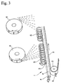
- Fig. 3 shows an embodiment of a shot peening apparatus for carrying out the invention.
- Reference numeral 1 in the figure is a conveyer belt, which is approximately constructed by turning a belt 3 around a pulley 2.
- a pair of parallel guide shafts 4 and 4 is arranged along the upper surface of the belt 3.
- a plurality of pins 5 are attached on the upper surface of the belt 3, and the pins 5 project upwardly through the intermediate of the guide shafts 4 and 4.
- the guide shafts 4 and 4 are rotatable in the same direction around the axis thereof, so that coil springs S on the guide shafts 4 and 4 are rotated, and pin 5 engages with the coil spring S to travel it.
- a pair of ablator wheels 6 and 6 which rotate in mutually opposite directions is arranged above the thus constructed a conveyer belt 1, so as to project shot on the end surface and the side surface of the coil spring S.
- the above construction is a shot peening apparatus for performing preliminary warm shot peening, and the apparatus can also be applied to warm stress shot peening.
- the coil spring S is passed two times through one shot peening apparatus, thereby performing preliminary warm shot peening and warm stress shot peening.
- two shot peening apparatuses may be arranged and preliminary warm shot peening and warm stress shot peening are respectively performed in each shot peening apparatus.
- the coil spring S can be heated by heating in tempering or annealing, or alternatively, an optional heating furnace can be provided at the upstream of the shot peening apparatus, or can be provided intermediate between the two shot peening apparatus.
- a jig 10 shown in Fig. 4B can be used in warm stress shot peening.
- reference numeral 11 is a disk, of which the center portion is attached to a shaft 12.
- a disk 13 is slidably fitted to the end of the shaft 12 in the axial direction thereof.
- the disk 13 is clamped to the right in the figure by a nut 14 screwed at the end of the shaft 12.
- the coil spring S which was in a free state shown in Fig. 4A, is compressed in the distance L, whereby predetermined stress is imparted thereto.
- the coil spring S installed to the jig 10 is passed through a shot peening apparatus as shown in Fig. 3, and warm stress shot peening is performed.
- Coil springs with specifications shown in Table 1 were produced from a wire made from a material specified by the Japanese Industrial Standard No. SUP7 with a diameter of 12.5 mm, and they were subjected to thermal refining through quenching and tempering to have hardnesses in the range of 2.5 to 2.65 HBD.
- the coil springs were maintained in a heating furnace at 315°C for 20 minutes, and they were then subjected to preliminary warm shot peening, in which shot was projected on the end surface of the coil spring, by passing the coil spring through the shot peening apparatus shown in Fig. 3.
- the chemical composition of the coil spring was 0.59% C, 0.85% Mn, 2.05% Si, 0.15% Cr, and the balance Fe by weight %.
- the coil spring was installed in the jig shown in Fig. 4B and was compressed to be imparted with stress of 75 kgf/mm 2 .
- the coil spring was then pre-heated at 315°C similarly as the above, and was subjected to warm stress shot peening by passing it through the shot peening apparatus.
- a cut wire with a diameter of 0.87 mm was used as shot in the preliminary warm shot peening and the warm stress shot peening.
- Example 1 of the invention A coil spring the same as in Example 1 of the invention, was subjected to preliminary warm shot peening under the same conditions as Example 1. The coil spring was subjected to a first warm stress shot peening, and was then subjected to a second warm stress shot peening under the same conditions as the first warm stress shot peening except for using a cut wire with a diameter of 0.67 mm as shot.
- Comparative Example 1 shot peening in room temperature was performed two times instead of the preliminary warm shot peening and the warm stress shot peening in the invention. In the second shot peening, a cut wire with a diameter of 0.67 mm was used as the shot. A coil spring of Comparative Example 1 was produced under the same conditions as the examples of the invention except for the above conditions.
- the coil springs in Examples 1 and 2 of the invention and Comparative Examples 1 to 3 were subjected to setting in which a stress of 134.1 kgf/mm 2 was applied thereto, and they were subjected to a durability test after being subjected to painting and drying at 150°C serving as low temperature annealing.
- the coil spring was installed in a durability test machine applying stress of 75 kgf/mm 2 thereto, and an alternating stress of ⁇ 45 kgf/mm 2 was applied to the coil spring at a frequency of 5.0 Hz, whereby the number of cycles to failure was recorded.
- the results of the test were shown in Table 2.
- Example 2 of the invention was further subjected to a durability test under the same conditions as the above except that the alternating stress was ⁇ 55 kgf/mm 2 .
- the results of the tests are also shown in Table 2.
- No. Number of Cycles to Failure Note
- Example 1 of the Invention 1 938,600 2 1,000,000 Stopped at a million cycles with no breakage 3 1,000,000 4 704,200
- Comparative Example 2 1 287,400 Warm double shot peening 2 261,300 3 371,500 4 201,500 Comparative Example 3 1 302,800 Cold stress shot peening 2 383,800 3 344,400 4 347,600
- Example 1 of the invention the numbers of cycles to failure in Example 1 of the invention were approximately one million cycles, and the samples demonstrated superior durability.
- Example 2 of the invention in which warm stress double shot peening was performed, all the samples (Nos. 1 to 4) were not broken at a million cycles in the case when the alternative stress of ⁇ 45 kgf/mm 2 was applied in the installation state at 75 kgf/mm 2 , and good durability was demonstrated even in the case when the alternative stress of ⁇ 55 kgf/mm 2 was applied (Nos. 5 to 8).
- Comparative Example 2 in which cold double shot peening was performed the numbers of cycles were about 100,000, and this showed that the samples are not able for practical use.
- Fig. 5 shows a distribution of residual stress imparted by each shot peening condition. Residual stress severely affects the fatigue strength, and it has been demonstrated that larger residual strength and deeper distribution thereof are more suitable for improvement of the fatigue strength. Observing the residual stress distribution in each condition of the shot peening shown in Fig. 5 from this point of view, the residual stress in the cold double shot peening, in which the fatigue strength was smallest, had the smallest distribution, and the peak value thereof is -900 MPa. The residual stresses in the warm shot peening and the cold stress shot peening, in which the fatigue strengths are almost the same, had almost the same distribution, and the peak values thereof are about -1300 MPa. In contrast, the residual stresses in the warm stress shot peening and the warm stress double shot peening, in which the fatigue strengths are very high, had greatly large distributions in comparison with the others, and the peak values thereof are -1600 MPa or more.
- the invention is not limited to the spring.
- the invention can be applied to any spring, such as leaf springs, disk springs, torsion bars, tension rods, and stabilizers.
Landscapes
- Chemical & Material Sciences (AREA)
- Engineering & Computer Science (AREA)
- Mechanical Engineering (AREA)
- Crystallography & Structural Chemistry (AREA)
- Materials Engineering (AREA)
- Metallurgy (AREA)
- Organic Chemistry (AREA)
- General Engineering & Computer Science (AREA)
- Physics & Mathematics (AREA)
- Thermal Sciences (AREA)
- Springs (AREA)
- Heat Treatment Of Articles (AREA)
Abstract
Description
Temperatures for Warm Stress Shot Peening: 150 to 350°C
| Wire Diameter r (mm) | Average Coil Diameter R Number (mm) | Effective Winding | Spring Constant (kgf/mm) | Free Length (mm) |
| 12.5 | 110 | 5.39 | 3.40 | 382 |
| No. | Number of Cycles to Failure | Note | |
| Example 1 of the Invention | 1 | 938,600 | |
| 2 | 1,000,000 | Stopped at a million cycles with no | |
| 3 | 1,000,000 | ||
| 4 | 704,200 | ||
| Example 2 of the Invention | 1 to 4 | 1,000,000 | Stopped at a million cycles with no |
| 5 | 255,300 | ||
| 6 | 314,200 | ||
| 7 | 456,100 | ||
| 8 | 605,400 | ||
| Comparative Example 1 | 1 | 96,200 | Cold double shot peening |
| 2 | 118,500 | ||
| 3 | 85,300 | ||
| 4 | 104,600 | ||
| Comparative Example 2 | 1 | 287,400 | Warm double shot peening |
| 2 | 261,300 | ||
| 3 | 371,500 | ||
| 4 | 201,500 | ||
| Comparative Example 3 | 1 | 302,800 | Cold stress shot |
| 2 | 383,800 | ||
| 3 | 344,400 | ||
| 4 | 347,600 |
Claims (8)
- A production process for highly strengthened springs, the process comprising:performing a first shot peening on a spring steel having a hardness of 550HV or more, corresponding to a diameter of 2.7 mm or less on a Brinell ball mark, while applying stress to the springs at a warm temperature in a range of 150 to 350°C.
- A production process for highly strengthened springs according to claim 1, wherein a second shot peening is performed on the spring steel using shot with a diameter smaller than that of the first shot peening while applying stress to the spring at a warm temperature in the range of 150 to 350°C.
- A production process for highly strengthened springs according to claim 1, wherein the stress is applied by a jig which contacts a portion of the spring, at least the portion of the springs is subjected to preliminary warm shot peening at a temperature in the range of 150 to 350°C before the first shot peening at a warm temperature in the range of 150 to 350°C.
- A production process for highly strengthened springs according to claim 1, wherein the stress is 75 kgf/mm2 or more.
- A highly strengthened spring obtained by performing a first shot peening on a spring steel having a hardness of 550HV or more, corresponding to a diameter of 2.7 mm or less on a Brinell ball mark, while applying stress to the spring at a warm temperature in the range of 150 to 350°C.
- A highly strengthened spring according to claim 5, wherein a second shot peening is performed on the spring steel using shot with a smaller diameter than that in the first shot peening while applying stress to the springs at a warm temperature in the range of 150 to 350°C.
- A highly strengthened spring according to claim 5, wherein the stress is applied by a jig which contacts a portion of the spring, at least the portion of the spring is subjected to preliminary warm shot peening at a temperature in the range of 150 to 350°C before the shot peening at a warm temperature in the range of 150 to 350°C.
- A highly strengthened spring according to claim 5, wherein the stress is 75 kgf/mm2 or more.
Applications Claiming Priority (3)
| Application Number | Priority Date | Filing Date | Title |
|---|---|---|---|
| JP16070699 | 1999-06-08 | ||
| JP16070699 | 1999-06-08 | ||
| PCT/JP2000/003730 WO2000075381A1 (en) | 1999-06-08 | 2000-06-08 | High-strength spring and production method therefor |
Publications (4)
| Publication Number | Publication Date |
|---|---|
| EP1201773A1 true EP1201773A1 (en) | 2002-05-02 |
| EP1201773A9 EP1201773A9 (en) | 2002-07-31 |
| EP1201773A4 EP1201773A4 (en) | 2004-12-08 |
| EP1201773B1 EP1201773B1 (en) | 2009-04-22 |
Family
ID=15720715
Family Applications (1)
| Application Number | Title | Priority Date | Filing Date |
|---|---|---|---|
| EP00937195A Expired - Lifetime EP1201773B1 (en) | 1999-06-08 | 2000-06-08 | High-strength spring and production method therefor |
Country Status (8)
| Country | Link |
|---|---|
| US (1) | US6544360B1 (en) |
| EP (1) | EP1201773B1 (en) |
| JP (1) | JP4042953B2 (en) |
| CN (1) | CN1135269C (en) |
| BR (1) | BR0011428A (en) |
| DE (1) | DE60042074D1 (en) |
| ES (1) | ES2325351T3 (en) |
| WO (1) | WO2000075381A1 (en) |
Cited By (6)
| Publication number | Priority date | Publication date | Assignee | Title |
|---|---|---|---|---|
| WO2008130742A3 (en) * | 2007-04-17 | 2009-02-19 | Meritor Suspension Systems Co | Peening method for vehicle suspension spring with ceramic peening media |
| WO2010136010A1 (en) * | 2009-05-28 | 2010-12-02 | Mtu Aero Engines Gmbh | Method and apparatus for surface hardening a component, which is made of an intermetallic compound at least in the region of the surface to be hardened |
| DE112004000474B4 (en) * | 2003-03-26 | 2013-02-21 | Chuo Hatsujo K.K. | Method for producing a high-strength spring |
| WO2015181916A1 (en) * | 2014-05-28 | 2015-12-03 | 日本発條株式会社 | Suspension spring device and suspension coil spring |
| DE102016012941B4 (en) * | 2016-10-28 | 2019-06-06 | Mvo Gmbh Metallverarbeitung Ostalb | Process for machining a toothed rack and subsequently machined rack |
| US20210114116A1 (en) * | 2018-06-29 | 2021-04-22 | Ab Sandvik Coromant | Method of treating a cutting tool, and a cutting tool |
Families Citing this family (31)
| Publication number | Priority date | Publication date | Assignee | Title |
|---|---|---|---|---|
| ES2399388T3 (en) * | 2001-12-26 | 2013-04-01 | Nhk Spring Co., Ltd. | Leaf spring for vehicle and method for producing the leaf spring |
| US6811149B1 (en) | 2003-10-27 | 2004-11-02 | Daniel E. Johnson | Fatigue and damage tolerant coil spring |
| JP4770238B2 (en) * | 2005-03-31 | 2011-09-14 | Jfeスチール株式会社 | Warm shot peening method for thick steel plate |
| DE502007001162D1 (en) * | 2006-06-23 | 2009-09-10 | Muhr & Bender Kg | Surface layer improvement of disc springs or corrugated springs |
| EP2145705B1 (en) * | 2007-03-14 | 2016-08-24 | Shinko Metal Products Co., Ltd. | Seamless steel pipe and hollow spring utilizing the seamless steel pipe |
| JP5312973B2 (en) * | 2009-02-10 | 2013-10-09 | 日本発條株式会社 | Torsion bar and manufacturing method thereof |
| JP5322744B2 (en) * | 2009-04-03 | 2013-10-23 | 日本発條株式会社 | Compression coil spring and method of manufacturing coil spring |
| JP5393281B2 (en) * | 2009-06-17 | 2014-01-22 | 日本発條株式会社 | Coil spring manufacturing method |
| JP5393280B2 (en) * | 2009-06-17 | 2014-01-22 | 日本発條株式会社 | Coil spring for vehicle suspension and manufacturing method thereof |
| US8506732B2 (en) * | 2009-08-07 | 2013-08-13 | Radyne Corporation | Heat treatment of helical springs or similarly shaped articles by electric resistance heating |
| JP5639064B2 (en) * | 2009-09-11 | 2014-12-10 | 新日鐵住金株式会社 | Method for producing carbonitrided member |
| US8328169B2 (en) * | 2009-09-29 | 2012-12-11 | Chuo Hatsujo Kabushiki Kaisha | Spring steel and spring having superior corrosion fatigue strength |
| JP5511067B2 (en) * | 2010-05-21 | 2014-06-04 | 日本発條株式会社 | Coil spring manufacturing method |
| US9623475B2 (en) * | 2010-07-26 | 2017-04-18 | Chuo Hatsujo Kabushiki Kaisha | Method for producing spring |
| CN102338182A (en) * | 2010-07-27 | 2012-02-01 | 上海中国弹簧制造有限公司 | Production process for automobile suspension spring |
| CN101947558A (en) * | 2010-08-30 | 2011-01-19 | 南京钢铁股份有限公司 | Temperature control rolling method for high-strength spring steel belt |
| JP5711539B2 (en) | 2011-01-06 | 2015-05-07 | 中央発條株式会社 | Spring with excellent corrosion fatigue strength |
| DE102011051209B4 (en) * | 2011-06-20 | 2013-03-21 | Benteler Automobiltechnik Gmbh | Method and device for producing a motor vehicle stabilizer bar |
| DE102011055104B4 (en) | 2011-11-07 | 2014-07-17 | Benteler Automobiltechnik Gmbh | Method for solidifying blasting of metal components and blasting machine for carrying out the method |
| CN102443686A (en) * | 2012-01-09 | 2012-05-09 | 东风汽车悬架弹簧有限公司 | Surface shot blasting reinforcement method of steel plate spring |
| US9862057B2 (en) | 2012-12-12 | 2018-01-09 | United Technologies Corporation | Vacuum degassing laser-blocking material system and process |
| JP6194526B2 (en) * | 2013-06-05 | 2017-09-13 | 高周波熱錬株式会社 | Method and apparatus for heating plate workpiece and hot press molding method |
| JP6318048B2 (en) | 2014-08-20 | 2018-04-25 | 日本発條株式会社 | Impeller lift peening machine |
| EP3438493B1 (en) * | 2016-03-30 | 2021-03-03 | NHK Spring Co., Ltd. | Hollow spring member and manufacturing method therefor |
| CN107267724A (en) * | 2017-06-28 | 2017-10-20 | 江苏铭远杆塔有限公司 | Steel tube tower component surface refined crystalline strengthening intensifier |
| JP6503482B2 (en) * | 2018-01-29 | 2019-04-17 | 日本発條株式会社 | Coil spring |
| EP3838448A1 (en) * | 2019-12-20 | 2021-06-23 | Sandvik Mining and Construction Tools AB | Method of treating a mining insert |
| JP6935975B1 (en) * | 2020-03-24 | 2021-09-15 | 日立Astemo株式会社 | Manufacturing method of coil spring for suspension system of saddle type vehicle |
| JP7270572B2 (en) | 2020-03-24 | 2023-05-10 | 日立Astemo株式会社 | Projection material projection condition determination method and coil spring manufacturing method |
| WO2021192010A1 (en) * | 2020-03-24 | 2021-09-30 | 日立Astemo株式会社 | Production method for coil spring, and suspension device for saddle-ridden vehicle |
| CN115463994B (en) * | 2022-11-03 | 2023-03-24 | 广东神和新材料科技有限公司 | Manufacturing process of precise stainless steel spring wire for automobile |
Family Cites Families (9)
| Publication number | Priority date | Publication date | Assignee | Title |
|---|---|---|---|---|
| JPH05148537A (en) * | 1991-07-11 | 1993-06-15 | Tougou Seisakusho:Kk | Coil spring manufacturing method |
| JPH0531671A (en) * | 1991-07-22 | 1993-02-09 | Chuo Spring Co Ltd | Coil spring peening method |
| JP3262352B2 (en) * | 1991-11-18 | 2002-03-04 | 日本発条株式会社 | Manufacturing method of high strength spring |
| US5258082A (en) | 1991-11-18 | 1993-11-02 | Nhk Spring Co., Ltd. | High strength spring |
| JP2994508B2 (en) | 1991-11-26 | 1999-12-27 | 株式会社東郷製作所 | Manufacturing method of coil spring |
| JPH05179349A (en) * | 1991-12-27 | 1993-07-20 | Chuo Spring Co Ltd | Spring post-processing method |
| JP3173756B2 (en) | 1994-07-28 | 2001-06-04 | 株式会社東郷製作所 | Manufacturing method of coil spring |
| JPH09279229A (en) | 1996-04-15 | 1997-10-28 | Suncall Corp | Surface treatment of steel work |
| US6022427A (en) | 1997-02-08 | 2000-02-08 | Fried Krupp | Method for producing helical springs |
-
2000
- 2000-06-08 JP JP2001501659A patent/JP4042953B2/en not_active Expired - Lifetime
- 2000-06-08 CN CNB008085978A patent/CN1135269C/en not_active Expired - Lifetime
- 2000-06-08 DE DE60042074T patent/DE60042074D1/en not_active Expired - Lifetime
- 2000-06-08 WO PCT/JP2000/003730 patent/WO2000075381A1/en not_active Ceased
- 2000-06-08 EP EP00937195A patent/EP1201773B1/en not_active Expired - Lifetime
- 2000-06-08 US US09/980,127 patent/US6544360B1/en not_active Expired - Lifetime
- 2000-06-08 ES ES00937195T patent/ES2325351T3/en not_active Expired - Lifetime
- 2000-06-08 BR BR0011428-6A patent/BR0011428A/en not_active IP Right Cessation
Cited By (11)
| Publication number | Priority date | Publication date | Assignee | Title |
|---|---|---|---|---|
| DE112004000474B4 (en) * | 2003-03-26 | 2013-02-21 | Chuo Hatsujo K.K. | Method for producing a high-strength spring |
| WO2008130742A3 (en) * | 2007-04-17 | 2009-02-19 | Meritor Suspension Systems Co | Peening method for vehicle suspension spring with ceramic peening media |
| US7946009B2 (en) | 2007-04-17 | 2011-05-24 | Mssc Us | Peening method for vehicle suspension spring |
| WO2010136010A1 (en) * | 2009-05-28 | 2010-12-02 | Mtu Aero Engines Gmbh | Method and apparatus for surface hardening a component, which is made of an intermetallic compound at least in the region of the surface to be hardened |
| US20120055222A1 (en) * | 2009-05-28 | 2012-03-08 | Mtu Aero Engines Gmbh | Method and apparatus for surface hardening a component, which is made of an intermetallic compound at least in the region of the surface to be hardened |
| WO2015181916A1 (en) * | 2014-05-28 | 2015-12-03 | 日本発條株式会社 | Suspension spring device and suspension coil spring |
| EP3150880B1 (en) | 2014-05-28 | 2019-01-30 | NHK Spring Co., Ltd. | Suspension spring device and suspension coil spring |
| US10583706B2 (en) | 2014-05-28 | 2020-03-10 | Nhk Spring Co., Ltd. | Method of manufacturing a suspension coil spring |
| DE102016012941B4 (en) * | 2016-10-28 | 2019-06-06 | Mvo Gmbh Metallverarbeitung Ostalb | Process for machining a toothed rack and subsequently machined rack |
| US20210114116A1 (en) * | 2018-06-29 | 2021-04-22 | Ab Sandvik Coromant | Method of treating a cutting tool, and a cutting tool |
| US12420340B2 (en) * | 2018-06-29 | 2025-09-23 | Ab Sandvik Coromant | Method of treating a cutting tool, and a cutting tool |
Also Published As
| Publication number | Publication date |
|---|---|
| EP1201773B1 (en) | 2009-04-22 |
| US6544360B1 (en) | 2003-04-08 |
| DE60042074D1 (en) | 2009-06-04 |
| BR0011428A (en) | 2002-03-26 |
| EP1201773A4 (en) | 2004-12-08 |
| CN1354802A (en) | 2002-06-19 |
| WO2000075381A1 (en) | 2000-12-14 |
| CN1135269C (en) | 2004-01-21 |
| EP1201773A9 (en) | 2002-07-31 |
| JP4042953B2 (en) | 2008-02-06 |
| ES2325351T3 (en) | 2009-09-02 |
Similar Documents
| Publication | Publication Date | Title |
|---|---|---|
| US6544360B1 (en) | Highly strengthened spring and process for producing the same | |
| JPWO2000075381A1 (en) | High strength spring and manufacturing method thereof | |
| EP3527685B1 (en) | Apparatus for production of a coil spring and its use | |
| CN1327024C (en) | Steel wire for hard drawn spring excellent in fatigue strength and resistance to settling, and hard drawn spring | |
| Fuentes et al. | Premature fracture in automobile leaf springs | |
| WO2012121115A1 (en) | Spring and manufacturing method thereof | |
| CN100430249C (en) | Leaf spring for vehicle and manufacturing method thereof | |
| WO2018190331A1 (en) | Helical compression spring and method for producing same | |
| JPH0841533A (en) | Coil spring manufacturing method | |
| CN108179355A (en) | A kind of high-intensity and high-tenacity spring steel wire and its preparation process | |
| US5225008A (en) | Method for manufacturing a high-strength spring | |
| US5152851A (en) | High-strength coil spring and method of producing same | |
| KR910003978B1 (en) | High tensile ductility liner with improved ductility | |
| JP2024170474A (en) | Compression spring | |
| EP0614994B1 (en) | Spring steel wires and process for producing the same | |
| EP0431224A1 (en) | Method of manufacturing a leaf of a leaf spring | |
| JP2682645B2 (en) | Oil tempered hard drawn steel wire spring and method for manufacturing the same | |
| EP0303041B1 (en) | Oil-quenched and tempered hard drawn steel wire with a shaped section, and process for producing the same | |
| EP1036851A1 (en) | High fatigue-strength steel wire and spring, and processes for producing these | |
| JPH05331597A (en) | High fatigue strength coil spring | |
| Dighe | A review on testing of steel leaf spring | |
| JPH0734134A (en) | Crankshaft surface treatment method | |
| KR20250176443A (en) | Coil springs and their manufacturing methods and apparatus | |
| JPS61218843A (en) | Steel spring and manufacture thereof | |
| WO2023120491A1 (en) | Compression coil spring and method for manufacturing same |
Legal Events
| Date | Code | Title | Description |
|---|---|---|---|
| PUAI | Public reference made under article 153(3) epc to a published international application that has entered the european phase |
Free format text: ORIGINAL CODE: 0009012 |
|
| 17P | Request for examination filed |
Effective date: 20011127 |
|
| AK | Designated contracting states |
Kind code of ref document: A1 Designated state(s): DE ES FR GB IT |
|
| A4 | Supplementary search report drawn up and despatched |
Effective date: 20041027 |
|
| 17Q | First examination report despatched |
Effective date: 20050420 |
|
| 17Q | First examination report despatched |
Effective date: 20050420 |
|
| GRAP | Despatch of communication of intention to grant a patent |
Free format text: ORIGINAL CODE: EPIDOSNIGR1 |
|
| GRAS | Grant fee paid |
Free format text: ORIGINAL CODE: EPIDOSNIGR3 |
|
| GRAA | (expected) grant |
Free format text: ORIGINAL CODE: 0009210 |
|
| RAP1 | Party data changed (applicant data changed or rights of an application transferred) |
Owner name: NHK SPRING CO., LTD. |
|
| AK | Designated contracting states |
Kind code of ref document: B1 Designated state(s): DE ES FR GB IT |
|
| REG | Reference to a national code |
Ref country code: GB Ref legal event code: FG4D |
|
| REF | Corresponds to: |
Ref document number: 60042074 Country of ref document: DE Date of ref document: 20090604 Kind code of ref document: P |
|
| REG | Reference to a national code |
Ref country code: ES Ref legal event code: FG2A Ref document number: 2325351 Country of ref document: ES Kind code of ref document: T3 |
|
| PLBE | No opposition filed within time limit |
Free format text: ORIGINAL CODE: 0009261 |
|
| STAA | Information on the status of an ep patent application or granted ep patent |
Free format text: STATUS: NO OPPOSITION FILED WITHIN TIME LIMIT |
|
| 26N | No opposition filed |
Effective date: 20100125 |
|
| REG | Reference to a national code |
Ref country code: FR Ref legal event code: PLFP Year of fee payment: 17 |
|
| REG | Reference to a national code |
Ref country code: FR Ref legal event code: PLFP Year of fee payment: 18 |
|
| REG | Reference to a national code |
Ref country code: FR Ref legal event code: PLFP Year of fee payment: 19 |
|
| PGFP | Annual fee paid to national office [announced via postgrant information from national office to epo] |
Ref country code: IT Payment date: 20190620 Year of fee payment: 20 Ref country code: DE Payment date: 20190528 Year of fee payment: 20 |
|
| PGFP | Annual fee paid to national office [announced via postgrant information from national office to epo] |
Ref country code: FR Payment date: 20190510 Year of fee payment: 20 |
|
| PGFP | Annual fee paid to national office [announced via postgrant information from national office to epo] |
Ref country code: GB Payment date: 20190605 Year of fee payment: 20 Ref country code: ES Payment date: 20190702 Year of fee payment: 20 |
|
| REG | Reference to a national code |
Ref country code: DE Ref legal event code: R071 Ref document number: 60042074 Country of ref document: DE |
|
| REG | Reference to a national code |
Ref country code: GB Ref legal event code: PE20 Expiry date: 20200607 |
|
| PG25 | Lapsed in a contracting state [announced via postgrant information from national office to epo] |
Ref country code: GB Free format text: LAPSE BECAUSE OF EXPIRATION OF PROTECTION Effective date: 20200607 |
|
| REG | Reference to a national code |
Ref country code: ES Ref legal event code: FD2A Effective date: 20220128 |
|
| PG25 | Lapsed in a contracting state [announced via postgrant information from national office to epo] |
Ref country code: ES Free format text: LAPSE BECAUSE OF EXPIRATION OF PROTECTION Effective date: 20200609 |