JP6194526B2 - Method and apparatus for heating plate workpiece and hot press molding method - Google Patents
Method and apparatus for heating plate workpiece and hot press molding method Download PDFInfo
- Publication number
- JP6194526B2 JP6194526B2 JP2013119239A JP2013119239A JP6194526B2 JP 6194526 B2 JP6194526 B2 JP 6194526B2 JP 2013119239 A JP2013119239 A JP 2013119239A JP 2013119239 A JP2013119239 A JP 2013119239A JP 6194526 B2 JP6194526 B2 JP 6194526B2
- Authority
- JP
- Japan
- Prior art keywords
- region
- heating
- plate
- workpiece
- heated
- Prior art date
- Legal status (The legal status is an assumption and is not a legal conclusion. Google has not performed a legal analysis and makes no representation as to the accuracy of the status listed.)
- Active
Links
Images


Classifications
-
- B—PERFORMING OPERATIONS; TRANSPORTING
- B21—MECHANICAL METAL-WORKING WITHOUT ESSENTIALLY REMOVING MATERIAL; PUNCHING METAL
- B21D—WORKING OR PROCESSING OF SHEET METAL OR METAL TUBES, RODS OR PROFILES WITHOUT ESSENTIALLY REMOVING MATERIAL; PUNCHING METAL
- B21D22/00—Shaping without cutting, by stamping, spinning, or deep-drawing
- B21D22/02—Stamping using rigid devices or tools
- B21D22/022—Stamping using rigid devices or tools by heating the blank or stamping associated with heat treatment
-
- C—CHEMISTRY; METALLURGY
- C21—METALLURGY OF IRON
- C21D—MODIFYING THE PHYSICAL STRUCTURE OF FERROUS METALS; GENERAL DEVICES FOR HEAT TREATMENT OF FERROUS OR NON-FERROUS METALS OR ALLOYS; MAKING METAL MALLEABLE, e.g. BY DECARBURISATION OR TEMPERING
- C21D1/00—General methods or devices for heat treatment, e.g. annealing, hardening, quenching or tempering
- C21D1/34—Methods of heating
- C21D1/40—Direct resistance heating
-
- C—CHEMISTRY; METALLURGY
- C21—METALLURGY OF IRON
- C21D—MODIFYING THE PHYSICAL STRUCTURE OF FERROUS METALS; GENERAL DEVICES FOR HEAT TREATMENT OF FERROUS OR NON-FERROUS METALS OR ALLOYS; MAKING METAL MALLEABLE, e.g. BY DECARBURISATION OR TEMPERING
- C21D1/00—General methods or devices for heat treatment, e.g. annealing, hardening, quenching or tempering
- C21D1/62—Quenching devices
- C21D1/673—Quenching devices for die quenching
-
- C—CHEMISTRY; METALLURGY
- C21—METALLURGY OF IRON
- C21D—MODIFYING THE PHYSICAL STRUCTURE OF FERROUS METALS; GENERAL DEVICES FOR HEAT TREATMENT OF FERROUS OR NON-FERROUS METALS OR ALLOYS; MAKING METAL MALLEABLE, e.g. BY DECARBURISATION OR TEMPERING
- C21D9/00—Heat treatment, e.g. annealing, hardening, quenching or tempering, adapted for particular articles; Furnaces therefor
- C21D9/46—Heat treatment, e.g. annealing, hardening, quenching or tempering, adapted for particular articles; Furnaces therefor for sheet metals
-
- H—ELECTRICITY
- H05—ELECTRIC TECHNIQUES NOT OTHERWISE PROVIDED FOR
- H05B—ELECTRIC HEATING; ELECTRIC LIGHT SOURCES NOT OTHERWISE PROVIDED FOR; CIRCUIT ARRANGEMENTS FOR ELECTRIC LIGHT SOURCES, IN GENERAL
- H05B3/00—Ohmic-resistance heating
- H05B3/0004—Devices wherein the heating current flows through the material to be heated
-
- H—ELECTRICITY
- H05—ELECTRIC TECHNIQUES NOT OTHERWISE PROVIDED FOR
- H05B—ELECTRIC HEATING; ELECTRIC LIGHT SOURCES NOT OTHERWISE PROVIDED FOR; CIRCUIT ARRANGEMENTS FOR ELECTRIC LIGHT SOURCES, IN GENERAL
- H05B3/00—Ohmic-resistance heating
- H05B3/02—Details
- H05B3/03—Electrodes
-
- C—CHEMISTRY; METALLURGY
- C21—METALLURGY OF IRON
- C21D—MODIFYING THE PHYSICAL STRUCTURE OF FERROUS METALS; GENERAL DEVICES FOR HEAT TREATMENT OF FERROUS OR NON-FERROUS METALS OR ALLOYS; MAKING METAL MALLEABLE, e.g. BY DECARBURISATION OR TEMPERING
- C21D2221/00—Treating localised areas of an article
- C21D2221/10—Differential treatment of inner with respect to outer regions, e.g. core and periphery, respectively
Description
本発明は、第1領域と第2領域を有する板状ワークを加熱するための板状ワークの加熱方法及び加熱装置と、これらを利用したホットプレス成形方法に関する。 The present invention relates to a heating method and a heating apparatus for a plate-like workpiece for heating a plate-like workpiece having a first region and a second region, and a hot press molding method using them.
従来、板状ワークに電極対を接触させ、電極間に電流を流して通電加熱する方法が知られている。この方法では、炉内に板状ワークを収容して行う、所謂炉加熱に比べて、加熱装置のコンパクト化を図れる。その反面、板状ワークの形状により加熱温度ムラが生じ易いことも知られている。そのため、このような通電加熱方法は、帯板、四角形等のシンプルな形状の板状ワークを加熱する際に利用されることが多かった。 2. Description of the Related Art Conventionally, a method is known in which an electrode pair is brought into contact with a plate-shaped workpiece, and an electric current is passed between the electrodes to perform energization heating. In this method, the heating device can be made more compact than the so-called furnace heating in which a plate-shaped workpiece is accommodated in the furnace. On the other hand, it is also known that uneven heating temperature is likely to occur due to the shape of the plate-like workpiece. For this reason, such an energization heating method is often used when heating a plate-shaped workpiece having a simple shape such as a strip or a rectangle.
近年ではシンプルな形状以外の板状ワークにも通電加熱を利用することが提案されている。例えば下記特許文献1では、自動車の構造部品のホットプレス成形において、複数の形状が組み合わされたような形状の板材を加熱する金属板の抵抗加熱方法が提案されている。
この特許文献1では、板状ワークに4個以上の電極を取り付け、2個の電極を選択して通電することで、複数の形状が組み合わされたような形状の板状ワークを均一な温度に加熱することができるとされている。
In recent years, it has been proposed to use energization heating for plate-like workpieces other than simple shapes. For example, Patent Document 1 below proposes a resistance heating method for a metal plate that heats a plate material having a shape in which a plurality of shapes are combined in hot press molding of a structural part of an automobile.
In Patent Document 1, four or more electrodes are attached to a plate-shaped workpiece, and two plates are selected and energized, so that a plate-shaped workpiece having a shape in which a plurality of shapes are combined is brought to a uniform temperature. It can be heated.
下記特許文献2には、板状ワークの一部の領域を焼入れしてプレス加工する方法が記載されている。この方法は、プレス加工する板状ワークの幅を長手方向で異ならせることで、一対の電極間に通電した際に電流密度が高い部位を設け、この部位を焼入れ温度以上に加熱している。ここでは、他の部位では電流密度が低いために焼入れ温度未満に維持されている。 Patent Document 2 listed below describes a method of quenching and pressing a partial region of a plate-like workpiece. In this method, by changing the width of the plate-like workpiece to be pressed in the longitudinal direction, a portion having a high current density is provided when energized between the pair of electrodes, and this portion is heated to the quenching temperature or higher. Here, since the current density is low in other parts, it is kept below the quenching temperature.
しかしながら、特許文献1のように板状ワークに複数の電極対を取り付けて通電加熱を行う加熱装置では、板状ワークを均一に加熱するために電極対が多数必要となるため、加熱装置の構造が複雑であった。
一方、特許文献2のように、板状のワークの複雑な形状を利用して部分加熱するのであれば、加熱装置の構造を簡素化することは可能であるものの、板状のワークの広い範囲を均一に加熱するとすれば、予め板状ワークの形状を熱処理に合わせた形状にしなければならず、生産性が低下する。
However, in a heating apparatus that performs current heating by attaching a plurality of electrode pairs to a plate-like workpiece as in Patent Document 1, a large number of electrode pairs are required to uniformly heat the plate-like workpiece. Was complicated.
On the other hand, as in Patent Document 2, if partial heating is performed using a complicated shape of a plate-like workpiece, the structure of the heating device can be simplified, but a wide range of plate-like workpieces. If the substrate is heated uniformly, the shape of the plate-like workpiece must be made in advance according to the heat treatment, and the productivity is lowered.
このような複数の形状が組み合わされたような形状を有する板状ワークを通電加熱する際、装置構成を簡素化するために長手方向の全長に電流を流して通電加熱することも考えられる。
ところが、単に長手方向の両端側から通電するとすれば、長手方向と直交する断面積が長手方向の途中位置で増加したり減少したりするため、電流流路に括れ部分や張出部分等が生じ、長手方向の途中位置で幅方向の電流密度の分布が過度に不均一になる。その結果、長手方向の途中位置に過剰に加熱された部位や過剰に加熱不足の部位が生じてしまい、全体を均一に加熱することは不可能であった。
When energizing and heating a plate-like workpiece having such a shape that a plurality of shapes are combined, it is also conceivable to energize and heat by passing an electric current through the entire length in the longitudinal direction in order to simplify the apparatus configuration.
However, if the current is simply applied from both ends in the longitudinal direction, the cross-sectional area perpendicular to the longitudinal direction increases or decreases in the middle of the longitudinal direction, so that a constricted portion, an overhanging portion, etc. are generated in the current flow path. The current density distribution in the width direction becomes excessively non-uniform at the middle position in the longitudinal direction. As a result, an excessively heated portion or an excessively insufficiently heated portion is generated at an intermediate position in the longitudinal direction, and it is impossible to uniformly heat the whole.
そこで本発明では、複雑な形状を有する板状ワークの広い範囲を容易に所定の温度範囲内に加熱できる、簡素な構成の板状ワークの加熱方法及び加熱装置を提供することを第1の目的とし、そのような加熱方法を利用できるホットプレス成形方法を提供することを第2の目的とする。 Accordingly, a first object of the present invention is to provide a heating method and a heating device for a plate-like workpiece having a simple configuration that can easily heat a wide range of a plate-like workpiece having a complicated shape within a predetermined temperature range. The second object is to provide a hot press molding method that can use such a heating method.
上記第1の目的を達成する本発明の板状ワークの加熱方法は、長軸に沿って狭幅部と広幅部とを備え、狭幅部の両側縁をそれぞれ長軸に沿って延長して得られる仮想区画線により広幅部内に区画された仮想延長部と狭幅部とを有し幅又は幅方向の断面積が長手方向に沿って単調増加若しくは減少する第1領域と、広幅部における第1領域の一部に隣接して一体に設けられた第2領域と、を有する板状ワークの加熱方法であって、第2領域を加熱した後、一対の電極を幅方向に配置して板状ワークの表面に接触させ、通電しつつ一方又は双方の電極を第1領域の断面積の変化に応じて長手方向に移動させて、第1領域を長手方向に通電加熱することで、第1領域及び第2領域を所定温度範囲内に加熱する方法である。 The heating method for a plate-like workpiece of the present invention that achieves the first object includes a narrow portion and a wide portion along the long axis, and extends both side edges of the narrow portion along the long axis. a first region in which the cross-sectional area of the partitioned width and a virtual extension portion and the narrow portion or the width direction of the wide portion increases or decreases monotonically along the length side direction by virtual lane marking obtained, the wide portion And a second region integrally provided adjacent to a part of the first region, and after heating the second region, a pair of electrodes are arranged in the width direction. By contacting the surface of the plate-shaped workpiece and energizing one or both electrodes in the longitudinal direction according to the change in the cross-sectional area of the first region , the first region is electrically heated in the longitudinal direction. In this method, the first region and the second region are heated within a predetermined temperature range.
この板状ワークの加熱方法は、長軸に沿って狭幅部と広幅部とを備え、狭幅部の両側縁をそれぞれ長軸に沿って延長して得られる仮想区画線により広幅部内に区画された仮想延長部と狭幅部とを有し幅が長手方向に沿って単調増加若しくは減少する第1領域と、広幅部における第1領域の一部に幅方向に隣接して一体に設けられた第2領域と、を有する板状ワークの加熱方法であって、第2領域を加熱した後、一対の電極を幅方向に配置して板状ワークの表面に接触させ、通電しつつ一方又は双方の電極を第1領域の断面積の変化に応じて長手方向に移動させて、第1領域を長手方向に通電加熱することで、第1領域及び第2領域を所定温度範囲内に加熱することができる。 This method of heating a plate-shaped workpiece is provided with a narrow portion and a wide portion along the long axis, and is partitioned in the wide portion by virtual partition lines obtained by extending both side edges of the narrow portion along the long axis. a first region width and a virtual extension portion and the narrow portion is increased or decreased monotonically along the length side direction which is provided integrally adjacent to a width direction to a portion of the first region in the wider portion A heating method for a plate-shaped workpiece having the second region, and after heating the second region, a pair of electrodes are arranged in the width direction to contact the surface of the plate-shaped workpiece and Alternatively, both the electrodes are moved in the longitudinal direction in accordance with the change in the cross-sectional area of the first region, and the first region and the second region are heated within a predetermined temperature range by energizing and heating the first region in the longitudinal direction. can do.
この方法では、第2領域は通電加熱、誘導加熱、炉加熱又はヒータ加熱の何れかにより加熱してもよい。第2領域を所定温度範囲より高い温度に加熱した後、第1領域を通電加熱するのが好適である。 In this method , the second region may be heated by energization heating, induction heating, furnace heating, or heater heating. It is preferable that the first region is heated by energization after the second region is heated to a temperature higher than the predetermined temperature range.
この板状ワークの加熱方法では、幅が長手方向に沿って単調増加若しくは減少する第1領域と、第1領域の長手方向に隣接して一体に設けられ第1領域より幅広の第2領域と、を有する板状ワークの加熱方法であって、第2領域を加熱した後、一対の電極を幅方向に配置して板状ワークの表面に接触させ、通電しつつ一方又は双方の電極を第1領域の断面積の変化に応じて長手方向に移動させるとともに、第1領域及び第2領域を長手方向に通電加熱することで、第1領域及び第2領域を所定温度範囲内に加熱することもできる。 The heating method of the plate-shaped workpiece, a first region monotonically increases or decreases a width along the long side direction, a second region of the wider than the first region provided integrally adjacent to a longitudinal direction of the first region And heating the second region, and then placing the pair of electrodes in the width direction so as to contact the surface of the plate-shaped workpiece, while energizing one or both electrodes. The first region and the second region are heated within a predetermined temperature range by moving in the longitudinal direction according to the change in the cross-sectional area of the first region and energizing and heating the first region and the second region in the longitudinal direction. You can also.
この方法では、第2領域は、通電加熱、誘導加熱、炉加熱又はヒータ加熱の何れかにより加熱してもよい。
さらに第2領域を所定温度範囲より低い温度に加熱した後、第1領域及び第2領域を通電加熱するのが好適である。
In this method, the second region may be heated by energization heating, induction heating, furnace heating, or heater heating.
Furthermore, it is preferable that the first region and the second region are heated by energization after the second region is heated to a temperature lower than the predetermined temperature range.
これらの方法では、一対の電極を幅方向に配置して板状ワークの表面に接触させ、一方又は双方の電極を通電しつつ長手方向に移動させることで、第1領域を長手方向に通電加熱するのが好適である。 In these methods, a pair of electrodes are arranged in the width direction, brought into contact with the surface of the plate-like workpiece, and one or both electrodes are moved in the longitudinal direction while energizing, whereby the first region is energized and heated in the longitudinal direction. It is preferable to do this.
上記第1の目的を達成する本発明の板状ワークの加熱装置は、長軸に沿って狭幅部と広幅部とを備え、狭幅部の両側縁をそれぞれ長軸に沿って延長して得られる仮想区画線により広幅部内に区画された仮想延長部と狭幅部とを有し幅が長手方向に沿って単調増加若しくは減少する第1領域と、第1領域の一部に幅方向に隣接して一体に設けられた第2領域と、を有する板状ワークを加熱する加熱装置であって、第1領域を加熱する第1加熱部と、第2領域を加熱する第2加熱部と、を備え、第1加熱部は、幅方向に沿って配置されて板状ワークの表面に接触する一対の電極と、一方又は双方の電極を通電しつつ第1領域の断面積の変化に応じて長手方向に移動させる駆動機構と、を有する。 The heating device for a plate-like workpiece of the present invention that achieves the first object includes a narrow portion and a wide portion along the long axis, and extends both side edges of the narrow portion along the long axis. a first region width and a and a narrow width portion virtual extension portions partitioned into wide portion increases or decreases monotonically along the length side direction by virtual lane marking obtained, the width direction to a portion of the first region A heating device for heating a plate-like workpiece having a second region integrally provided adjacent to the first region, a first heating unit for heating the first region, and a second heating unit for heating the second region The first heating unit is arranged along the width direction and contacts the surface of the plate-like workpiece, and changes in the cross-sectional area of the first region while energizing one or both electrodes And a drive mechanism for moving in the longitudinal direction accordingly .
上記第1の目的を達成する本発明の他の板状ワークの加熱装置は、幅が長手方向に沿って単調増加若しくは減少する第1領域と、第1領域と長手方向に隣接して一体に設けられて第1領域より幅広の第2領域と、を有する板状ワークの加熱装置であって、第2領域を加熱する部分加熱部と、第1領域及び第2領域を加熱する全体加熱部と、を備え、全体加熱部は、幅方向に沿って配置されて板状ワークの表面に接触して通電する一対の電極と、一方又は双方の電極を通電しつつ第1領域の断面積の変化に応じて長手方向に移動させる駆動機構と、を有する。 The first other heating device of the plate-shaped workpiece of the present invention to achieve the object of a first region of monotonically increasing or decreasing width along the long side direction, integrally adjacent to the first region and the longitudinal A heating apparatus for a plate-shaped workpiece having a second area wider than the first area, a partial heating unit for heating the second area, and overall heating for heating the first area and the second area And the entire heating unit is disposed along the width direction and is in contact with the surface of the plate-shaped workpiece and energized, and the cross-sectional area of the first region while energizing one or both electrodes And a drive mechanism that moves in the longitudinal direction in accordance with the change of the .
上記第2の目的を達成する本発明のホットプレス成形方法は、幅方向の断面積が長手方向に沿って単調増加若しくは減少する第1領域と、第1領域に隣接して一体に設けられた第2領域と、を有する板状ワークを、加熱してプレス成形するホットプレス成形方法であって、第2領域を加熱した後、一対の電極を幅方向に配置して板状ワークの表面に接触させ、通電しつつ一方又は双方の電極を第1領域の断面積の変化に応じて長手方向に移動させて、第1領域を長手方向に通電加熱することで、第1領域及び第2領域を所定温度範囲内に加熱して、プレス型により加圧する方法である。 Hot press forming method of the present invention to achieve the above second object, a first region is the cross-sectional area in the width direction increases or decreases monotonically along the longitudinal side direction, provided integrally adjacent to the first region A hot press molding method in which a plate-shaped workpiece having a second region is heated and press-molded, and after the second region is heated, a pair of electrodes are arranged in the width direction and the surface of the plate-shaped workpiece is The first region and the second region are heated by energizing and heating the first region in the longitudinal direction by moving one or both electrodes in the longitudinal direction in accordance with the change in the cross-sectional area of the first region. In this method, the region is heated within a predetermined temperature range and pressed by a press die.
本発明の上記ホットプレス成形方法では、幅方向の断面積が長手方向に沿って単調増加若しくは減少する第1領域と、第1領域に隣接して一体に設けられた第2領域と、を有する板状ワークを、加熱してプレス成形する際、一対の電極を幅方向に配置して板状ワークの表面に接触させ、一方又は双方の電極を通電しつつ第1領域の断面積の変化に応じてに長手方向に移動させるとともに第1領域及び第2領域を通電加熱し、プレス型により加圧してもよい。 The hot press molding method of the present invention has a first region in which a cross-sectional area in the width direction monotonously increases or decreases along the longitudinal direction, and a second region integrally provided adjacent to the first region. When a plate-like workpiece is heated and press-molded, a pair of electrodes are arranged in the width direction to be brought into contact with the surface of the plate-like workpiece, and one or both electrodes are energized to change the cross-sectional area of the first region. Accordingly , the first region and the second region may be energized and heated while being moved in the longitudinal direction and pressurized by a press die.
本発明の板状ワークの加熱方法及び加熱装置によれば、板状ワークを第1領域と第1領域の一部に隣接する第2領域との複数の領域に分けて加熱するので、各領域を簡素な形状にして加熱できる。このうち第1領域は、幅方向の断面積が長手方向に略一定であるか長手方向に沿って単調増加若しくは減少するかの形状を有するため、長手方向に通電する際、途中位置に電流の流路が括れる部分や張出す部分等がない。 According to the method and apparatus for heating a plate-like workpiece of the present invention, the plate-like workpiece is heated by being divided into a plurality of regions of a first region and a second region adjacent to a part of the first region. Can be heated in a simple shape. Of these, the first region has a shape in which the cross-sectional area in the width direction is substantially constant in the longitudinal direction or monotonously increases or decreases along the longitudinal direction. There is no part where the flow path can be confined or overhang.
そのため、第1領域に長手方向に通電加熱する際、幅方向の電流密度の分布が過度に不均一となる部分が生じない。従って、第1領域を断面積の長手方向に沿う変化に対応させて通電加熱することで、第1領域の広い範囲を容易に同程度に加熱でき、板状ワークを長手方向に効率良く加熱できる。 Therefore, when the first region is energized and heated in the longitudinal direction, a portion where the current density distribution in the width direction becomes excessively non-uniform does not occur. Therefore, by energizing and heating the first region corresponding to the change in the longitudinal direction of the cross-sectional area, a wide range of the first region can be easily heated to the same extent, and the plate-like workpiece can be efficiently heated in the longitudinal direction. .
そして第1領域の一部に隣接して設けられた第2領域を適切に調整して加熱した後、第2領域が適切な加熱状態となった時点で第1領域を加熱することで、第1領域及び第2領域を合わせた広い範囲を所定温度範囲内に加熱することが可能である。 And after adjusting the 2nd area | region provided adjacent to a part of 1st area | region appropriately and heating, when a 2nd area | region will be in an appropriate heating state, a 1st area | region is heated, A wide range including the first region and the second region can be heated within a predetermined temperature range.
さらに各領域を同時に加熱する必要がなく、第1領域を長手方向に纏めて通電加熱できると共に、第2領域に適した方法で加熱できるため、第1領域及び第2領域を合わせた広い範囲を簡素な構成で加熱することが可能である。 Furthermore, since it is not necessary to heat each region simultaneously, the first region can be heated by energization in the longitudinal direction, and can be heated by a method suitable for the second region, so that a wide range combining the first region and the second region can be obtained. Heating with a simple configuration is possible.
この板状ワークの加熱方法を、第2領域が第1領域の一部に幅方向に隣接して一体に設けられている板状ワークに適用した場合、先に第2領域を加熱すると、第2領域の温度が高くなるため、第1領域に比べて第2領域の抵抗が増加する。よって、第1領域を通電加熱する際、第2領域に流れる電流を少なくでき、板状ワークに第1領域に対応した所謂通電路が形成を形成できる。従って、第2領域を適切な加熱状態にした後で、第1領域を長手方向に通電加熱して第1領域を広い範囲で同程度に加熱することで、容易に第1領域及び第2領域の広い範囲を所定温度範囲内に加熱することができる。 When this plate-like workpiece heating method is applied to a plate-like workpiece in which the second region is integrally provided adjacent to a part of the first region in the width direction, when the second region is heated first, Since the temperature of the two regions becomes high, the resistance of the second region increases compared to the first region. Therefore, when the first region is energized and heated, the current flowing in the second region can be reduced, and a so-called energization path corresponding to the first region can be formed in the plate-shaped workpiece. Therefore, after the second region is appropriately heated, the first region and the second region are easily heated by energizing and heating the first region in the longitudinal direction to the same extent in a wide range. Can be heated within a predetermined temperature range.
また、この板状ワークの加熱方法を、第2領域が第1領域の長手方向に隣接して一体に設けられ、この第2領域が第1領域より幅広の板状ワークに適用した場合、先に第2領域を加熱すると、第2領域を予熱することができる。そのため第2領域を適切な加熱状態にした後で、第1領域及び第2領域を長手方向に通電加熱すれば、容易に第1領域及び第2領域の広い範囲を所定温度範囲内に加熱することができる。 Further, when this plate-shaped workpiece heating method is applied to a plate-shaped workpiece in which the second region is integrally provided adjacent to the longitudinal direction of the first region, and the second region is wider than the first region, When the second region is heated, the second region can be preheated. For this reason, if the first region and the second region are energized and heated in the longitudinal direction after the second region is appropriately heated, a wide range of the first region and the second region is easily heated within a predetermined temperature range. be able to.
以下、本発明の幾つかの実施形態について図を用いて詳細に説明する。
[第1実施形態]
本実施形態では、板状ワークWを加熱して冷却することで焼入処理を行う例を用いて説明する。この実施形態で加熱対象の板状ワークWは、鋼材からなる異形板であり、成形することで所望の製品形状、具体的には車体のBピラーが得られる外形となっている。
Hereinafter, some embodiments of the present invention will be described in detail with reference to the drawings.
[First Embodiment]
In the present embodiment, description will be given using an example in which a quenching process is performed by heating and cooling the plate-like workpiece W. In this embodiment, the plate-like workpiece W to be heated is a deformed plate made of a steel material, and has a desired product shape, specifically an outer shape from which a B pillar of the vehicle body can be obtained.
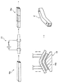
この板状ワークWは、図1(a)に示すように、幅方向の断面積が長手方向の一方向に沿って単調増加又は単調減少する第1領域11と、この第1領域11の一部、具体的には長手方向両端の幅方向両側に隣接して一体に設けられた複数の第2領域12と、を有している。板状ワークWの全体は略一定の厚みに形成され、第1領域11では幅が長手方向に沿って一方向に単調増加又は単調減少している。
As shown in FIG. 1A, the plate-like workpiece W includes a
幅方向の断面積が長手方向の一方向に沿って単調増加又は単調減少するとは、断面積の長手方向に沿う変化、即ち、長手方向の各位置における断面積が変曲点なく一方向側になる程増加するか、一方向側になる程減少することである。断面積の長手方向における急激な変化により、通電加熱時の電流密度が幅方向で過剰に不均一になることで、実用上問題となるような部分的な低温部位や高温部位が生じなければ、単調増加又は単調減少しているとみなすことができる。なお、幅方向の断面積が長手方向に略一定に連続していてもよい。 The cross-sectional area in the width direction monotonously increases or decreases monotonously along one direction in the longitudinal direction means that the cross-sectional area changes along the longitudinal direction, that is, the cross-sectional area at each position in the longitudinal direction is unidirectional without any inflection point. It is to increase as it is, or to decrease as it is in one direction. Due to the sudden change in the longitudinal direction of the cross-sectional area, the current density at the time of energization heating becomes excessively non-uniform in the width direction. It can be regarded as monotonically increasing or monotonically decreasing. The cross-sectional area in the width direction may be substantially constant in the longitudinal direction.
この実施形態の板状ワークWの場合、 長軸Lに沿って延びる狭幅部16と、狭幅部16の両端に一体に設けられた広幅部17と、を備えている。第1領域11は、狭幅部16と、狭幅部16の両側縁をそれぞれ長軸Lに沿って延長した仮想区画線16xにより広幅部17内に区画された仮想延長部11xと、で形成されている。なお、長軸Lは長手方向に沿う直線であれば適宜設定することが可能である。
In the case of the plate-like workpiece W according to this embodiment, the
このような板状ワークWを加熱するための加熱装置は、図1(c)(d)に示すように、第1領域11を加熱するための第1加熱部21と、図1(b)に示すように、第2領域12を加熱するための第2加熱部22と、を備えている。
As shown in FIGS. 1 (c) and 1 (d), the heating device for heating such a plate-like workpiece W includes a
第1加熱部21は、幅方向に沿って配置されて板状ワークWの表面に接触する一対の電極23,24と、一方の電極23を通電しつつ断面積の変化に対応するように長手方向に移動させる駆動機構25と、を備えている。
この実施形態の第1加熱部21では、一対の電極23,24が板状ワークWの幅全体を横断可能な長さに形成されている。この一対の電極23,24は、長手方向と直交して互いに平行に板状ワークWの第1領域11を横断するように表面に当接される。そして、一対の電極23,24のうち、一方の電極24が、給電部から一定の電流を流しつつ駆動機構25により板状ワークWの長手方向に沿って移動可能となっている。各電極23,24は転動可能なローラにより構成されていてもよい。
The
In the
駆動機構25では、板状ワークWの第1領域11の幅方向の断面積が大きい側から小さい側へ向けて移動速度を制御しつつ電極24を移動させることができる。ここでは板状ワークWの断面積の長手方向に沿う変化に対応するように、一対の電極23,24間の相対距離を広げることが可能となっている。
移動速度を制御することで、長手方向の各位置における通電時間を調整し、断面積の大きな部位の通電時間を長くすると共に、断面積の小さな部位の通電時間を短く制御し得る。これにより、第1領域11全体を所定温度範囲内、即ち、目標温度に対して許容される温度範囲に加熱制御し得る。この移動速度は、例えば板状ワークWの材質、形状、電流量、目標温度等、種々の条件に基づき、板状ワークWの長手方向の各位置における単位長さ当たりの発熱量が出来るだけ均等になるように制御するのがよい。
In the
By controlling the moving speed, the energization time at each position in the longitudinal direction can be adjusted, the energization time at the site with a large cross-sectional area can be lengthened, and the energization time at the site with a small cross-sectional area can be controlled short. As a result, the entire
第2加熱部22は、図1(b)に示すように、第1領域11の加熱を抑えて第2領域12を加熱できるものがよい。例えば、第2領域12に電極対を接触させて通電加熱により加熱してもよく、第2領域12にコイルを近接させて誘導加熱により加熱してもよく、第2領域12を部分的に加熱炉に収容して炉加熱により加熱してもよい。さらには所定温度に昇温されるヒータを接触させ、ヒータ加熱により加熱することも可能である。
なお、第2領域12に電極対を接触させて通電加熱する場合には、高周波電流を通電すると、表皮効果により第2領域12の外側縁側が強く加熱されるため、第2領域12だけを加熱し易くできる。
As shown in FIG. 1B, the
In addition, when the electrode pair is brought into contact with the
このような加熱装置を用いて板状ワークWを加熱するには、次のように行う。
まず図1(a)に示すように、板状ワークWの第1領域11及び第2領域12を特定する。第1領域11及び第2領域12は任意に設定できるため、できるだけ均一に加熱し易い形状にすることが望ましい。ここでは、狭幅部16の両側縁をそれぞれ長軸Lに沿って延長させることで、板状ワークWの長手方向両端側に仮想区画線16xを設定し、この仮想区画線16xにより広幅部17内に仮想延長部11xを設定する。そして、狭幅部16とその両端側の仮想延長部11xを合わせて第1領域11とし、仮想区画線16xと広幅部17の側縁との間をそれぞれ第2領域12とする。
In order to heat the plate-like workpiece W using such a heating device, the following is performed.
First, as shown to Fig.1 (a), the 1st area |
次いで、図1(b)に示すように、第2領域12を第2加熱部22に配置し、第2領域12を加熱する。このとき、第1領域11を加熱せずに第2領域12を加熱すると、第2領域12が高温状態に加熱されると共に、第1領域11が低温状態で保たれる。そのため第2領域12の抵抗が第1領域11の抵抗よりも大きくなり、次の第1領域11を通電加熱する際の通電路が形成されることになる。
Next, as illustrated in FIG. 1B, the
この第2領域12の加熱が終了する段階では、第2領域12を加熱処理の目標温度範囲よりも高い温度に加熱することが望ましい。これにより、次の第1領域11の通電加熱までの間に放熱により温度が低下しても、第2領域12を所定温度範囲内に加熱することが可能となる。
At the stage where the heating of the
次いで、第2領域12の加熱後、図1(c)(d)に示すように、一対の電極23,24を板状ワークWに接触させて給電部から電極23,24間に電流を流しつつ、電極24を長手方向に移動させることで、第1領域11を長手方向に通電加熱する。電極24の移動により、加熱初期には第1領域11の長手方向の一部の範囲に通電し、電極24を移動させることで通電範囲を広げ、終期では第1領域11の略全長に通電する。
Next, after heating the
このとき第2領域12が高温に加熱されているため、第2領域12の抵抗が大きくなることで、温度が低い第1領域11の範囲に電流が多く流れ、第1領域11が加熱される。これにより第1領域11が目標温度付近の所定温度範囲内に加熱される。
At this time, since the
第2領域12の加熱温度と第1領域の加熱タイミングとを調整することで、第1領域11及び第2領域12が所定温度範囲内に加熱される。なお、第2領域12の加熱と第1領域11の通電加熱との間の時間や熱伝達の程度によっては、第2領域12が放熱により温度が低下することがある。しかし、第2領域12の加熱時に過剰に昇温させていれば、昇温した第1領域11と放熱した第2領域12との温度が同等となり、第1領域11及び第2領域12を所定温度範囲内に加熱することができる。
この実施形態では、その後、急冷することで焼入処理を施している。
The
In this embodiment, after that, quenching is performed by rapid cooling.
以上ように板状ワークWを加熱すれば、板状ワークWを第1領域11と第2領域12との領域に分けて加熱するので、各領域を簡素な形状にして加熱できる。このうち第1領域11は、幅方向の断面積が長手方向に沿って単調増加若しくは減少する形状を有するため、長手方向に通電する際、途中位置に電流の流路が括れる部分がなく、電流が流れ難い張出部分等がない。
If the plate-like workpiece W is heated as described above, the plate-like workpiece W is heated by being divided into the
そのため第1領域11に長手方向に通電して抵抗加熱する際、幅方向の電流密度の分布が過度に不均一となる部分が生じることを防止できる。従って、第1領域11を断面積の長手方向に沿う変化に対応させて通電加熱することで、第1領域11の広い範囲を容易に同程度に加熱でき、板状ワークWを長手方向に効率良く加熱できる。
Therefore, when resistance heating is performed by energizing the
そして、第2領域12が適切な加熱状態となった後で第1領域11を加熱することで、第1領域11及び第2領域12を合わせた広い範囲を所定温度範囲内に加熱することが可能である。
さらに各領域を同時に加熱する必要がなく、第1領域11を長手方向に纏めて通電加熱できると共に、第2領域12に適した方法で加熱できるため、第1領域11及び第2領域12を合わせた広い範囲を簡素な構成で加熱することが可能である。
Then, by heating the
Furthermore, since it is not necessary to heat each region simultaneously, the
また第2領域12が第1領域11の一部に幅方向に隣接して一体に設けられている板状ワークWであるため、先に第2領域12を加熱すると板状ワークWに第1領域11に対応した通電路を形成できる。そのため第2領域12を適切な加熱状態にした後で、第1領域11を長手方向に通電加熱して第1領域11を広い範囲で同程度に加熱することで、容易に第1領域11及び第2領域12の広い範囲を所定温度範囲内に加熱することができる。
Moreover, since the 2nd area |
なお、上記第1実施形態では、仮想区画線16xを設定する際、狭幅部16の両側縁を延長して第1領域11を設定した例について説明したが、第1領域11の長手方向の各端部の幅を一定に維持するように仮想区画線16xを設定してもよい。その場合、第1領域11に一対の電極23,24を接触させて加熱するときに仮想延長部11xを他の部位より速く短時間で移動させることで、全体を均一に加熱できる。
さらに第1領域11の他の一部に、幅方向の断面積が長手方向に一定に保たれる範囲が存在する場合であっても、同様に電極23,24を他の部位よりも速い移動速度で短時間で移動させることで、第1領域11を均一に加熱することができる。
In the first embodiment, the example in which the
Furthermore, even in the case where there is a range where the cross-sectional area in the width direction is kept constant in the longitudinal direction in another part of the
[第2実施形態]
次に第2実施形態について説明する。この第2実施形態で処理する板状ワークWは第1実施形態と同様である。
即ち、板状ワークWは、長軸Lに沿って延びる狭幅部16と、狭幅部16の一方側の端部に設けられた広幅部17aと、挟幅部16の他方側の端部に設けられて広幅部17aよりさらに幅広の広幅部17bと、を一体に備えている。このワークWは、長手方向全長に設けられて幅方向の断面積が長手方向の一方側から他方側に向けて単調増加する第1領域11と、広幅部17aに設けられて第1領域11の一方側における幅方向両側に隣接する第2領域12aと、広幅部17bに設けられて第1領域11の他方側における幅方向両側に隣接する第2領域12bと、を有している。
[Second Embodiment]
Next, a second embodiment will be described. The plate-like workpiece W processed in the second embodiment is the same as that of the first embodiment.
That is, the plate-like workpiece W includes a
この実施形態では、板状ワークWを部分的に異なる温度範囲に加熱して冷却することで、異なる性状の部位を形成する。具体的には、広幅部17bを第1温度範囲に加熱し、広幅部17bを除く残部を第1温度範囲よりも高い第2温度範囲に加熱し、冷却することで、広幅部17bと広幅部17bを除く残部とで性状を異ならせる。
In this embodiment, the plate-like workpiece W is partially heated to a different temperature range and cooled to form portions having different properties. Specifically, the
使用する加熱装置は、第1加熱部21が異なる他は第1実施形態と同様である。この装置の第1加熱部21は、図2(c)(d)に示すように、電極24が広幅部17bの幅より短く第1領域11の最大幅に相当する長さを有し、一対の電極23,24の両方がそれぞれ駆動機構25a,25bにより板状ワークWの長手方向に移動可能に構成されている。その他は第1実施形態と同様である。
The heating device used is the same as that of the first embodiment except that the
この加熱装置を用いて板状ワークWを加熱するには、第1実施形態と同様に、予め図2(a)に示すように、板状ワークWの第1領域11及び第2領域12a,12bを設定する。
次いで図2(b)に示すように、第2領域12a,12bを第2加熱部22a,22bにそれぞれ配置して加熱する。この加熱時には、一方側の一対の第2領域12aを第2温度範囲よりも高い温度に加熱し、第2領域12bを第1温度範囲よりも高い温度に加熱するのがよい。
このように第1領域11を低温状態に維持して第2領域12a,12bが高温となるようにすることで、第2領域12a,12bの抵抗が第1領域11の抵抗よりも大きくなり、次の第1領域11を通電加熱する際の通電路を形成することができる。
In order to heat the plate-like workpiece W using this heating device, as shown in FIG. 2A in advance, as in the first embodiment, the
Next, as shown in FIG. 2B, the
Thus, by maintaining the
次いで、図2(c)(d)に実線で示すように、一対の電極23,24を第1領域11の中間部分、具体的には板状ワークWの狭幅部16と広幅部17bとの境界近傍に接触させる。ここでは一対の電極23,24を長手方向に対してそれぞれ略直交方向に、互いに略平行となるように第1領域11を横断させて配置する。
そして給電部から略一定の電流を電極23,24に流しつつ、各電極23,24を移動させて第1領域11の全長を長手方向に通電加熱する。電極24は駆動機構25aにより一方側に移動させ、他方の電極23は駆動機構25bにより他方側に移動させる。これにより、通電加熱の初期には第1領域11の長手方向の一部の範囲に通電し、電極23,24を離間させて通電範囲を広げ、終期には第1領域11の略全長に通電する。
Next, as shown by solid lines in FIGS. 2C and 2D, the pair of
The
このとき各電極23,24の移動順序や移動速度等は、第1領域11の形状、目標温度範囲等の各種の加熱条件に応じて制御するのがよい。
移動順序は、例えば電極23,24を同時に移動させてもよく、長い通電時間を要する側の電極24を先に移動させた後で電極23を移動させてもよい。移動速度は、例えば電極23と電極24とを異なる速度で移動させてもよく、電極23を第1領域11の幅方向の断面積の長手方向に沿う変化に対応させてもよい。
At this time, the moving order and moving speed of the
For example, the
電極23,24の移動順序や移動速度等を制御することで、長手方向の各位置における通電時間を調整し、断面積の大きな部位の通電時間を長くすると共に、断面積の小さな部位の通電時間を短くして、第1領域11の各位置を目標温度範囲に加熱する。ここでは広幅部17bの第1領域11を第1温度範囲に加熱し、残部の第1領域11を第2温度範囲に加熱する。
By controlling the moving order and moving speed of the
このように第1領域11の各位置を加熱すると、第2領域12a,12bが予め加熱されているため、第2領域12a,12bの加熱温度や第1領域11の加熱タイミング等を適宜調整することで、図2(e)に破線で示すように、広幅部17b全体を第1温度範囲内に加熱でき、残部全体を第2温度範囲内に加熱でき、板状ワークWに複数の温度領域を形成することができる。
この実施形態では、その後、急冷することで焼入処理を完了する。
When the respective positions of the
In this embodiment, quenching is then completed by rapid cooling.
以上ように板状ワークWを加熱しても、第1実施形態と同様の作用効果を得ることが可能である。特にこの第2実施形態では、第1領域11の加熱温度及び第2領域12a、12bの加熱温度を部位毎に異ならせて本発明を適用したので、各部位をそれぞれ異なる温度範囲内に加熱することができる。
Even when the plate-like workpiece W is heated as described above, the same effects as those of the first embodiment can be obtained. In particular, in the second embodiment, since the present invention is applied with the heating temperature of the
なお、第2実施形態では、板状ワークWとして厚みが全体で一定のものを用いたが、異なる厚みの領域が設けられたテーラードブランクを用いることも可能であり、例えば広幅部17bと残部とで異なる厚みを有する板状ワークWを同様にして加熱してもよい。その場合、広幅部17bと残部とを同じ温度範囲に加熱することも容易である。さらに均一な厚みであっても同様にして全体を同じ温度範囲に加熱してもよい。
In the second embodiment, the plate-like workpiece W having a constant thickness as a whole is used, but a tailored blank provided with regions having different thicknesses can also be used, for example, the
[第3実施形態]
次に、第3実施形態について説明する。
本実施形態で加熱対象の板状ワークWは、図3(a)に示すように、全体が略一定の厚みで略台形に形成され、幅方向の断面積が長手方向の一方向に沿って単調増加又は単調減少する第1領域11と、第1領域11より幅広の第2領域12と、を有している。
[Third Embodiment]
Next, a third embodiment will be described.
In the present embodiment, the plate-like workpiece W to be heated is formed in a substantially trapezoidal shape with a substantially constant thickness as shown in FIG. 3A, and the cross-sectional area in the width direction is along one direction in the longitudinal direction. The
このような板状ワークWを加熱するための加熱装置は、図3(b)(c)に示すように、第2領域12を加熱する部分加熱部としての第2加熱部22と、第1領域11及び第2領域12を加熱する全体加熱部としての第1加熱部21と、を備えている。
As shown in FIGS. 3B and 3C, the heating device for heating such a plate-like workpiece W includes a
第2加熱部22は、図3(b)に示すように、第1領域11の加熱を抑えて第2領域12を加熱できるものである。例えば、第2領域12に電極対を接触させて通電加熱により加熱してもよく、第2領域12にコイルを近接させて誘導加熱により加熱してもよく、第2領域12を部分的に加熱炉に収容して炉加熱により加熱してもよい。さらには所定温度に昇温されたヒータを接触させてヒータ加熱により加熱することも可能である。この例は第2領域12だけを加熱炉に収容して加熱している。
As shown in FIG. 3B, the
第1加熱部21は、図3(c)に示すように、幅方向に沿って互いに略平行に配置されて板状ワークWの表面に接触する一対の電極23,24を備え、給電部から一定の電流を供給して板状ワークWの長手方向に沿って一定の電流を流すことが可能となっている。
As shown in FIG. 3C, the
このような加熱装置を用いて板状ワークWを加熱するには、次のように行う。
まず図3(a)に示すように、出来るだけ均一に加熱できるように板状ワークWの第1領域11及び第2領域12を設定する。ここでは幅方向の断面積が大きくて、一対の電極23,24により通電加熱する場合に十分な電流密度を得難い部分を第2領域とし、幅方向の断面積が第2領域より小さい部分を第1領域とする。
In order to heat the plate-like workpiece W using such a heating device, the following is performed.
First, as shown to Fig.3 (a), the 1st area |
次いで、図3(b)に示すように、第2領域12を第2加熱部22に配置し、第2領域12を加熱する。第2加熱部22として加熱炉を用いており、第2領域を部分的に収容して加熱する。加熱処理の目標温度範囲よりも低い適度な温度までの予熱を行うのがよい。
Next, as illustrated in FIG. 3B, the
第2領域12の加熱後、図3(c)に示すように、一対の電極23,24を板状ワークWの両端の表面に接触させる。そして給電部から一定電流を供給して電極23,24間に電流を流して長手方向に通電加熱する。このとき第1領域11が所定温度範囲内となる条件で通電すると、第2領域12は幅広いため第1領域11に比べて単位面積当たりの発熱量が少なくなる。ところが第2領域12が適度に予熱されているため、この通電加熱により第1領域と第2領域との全体を所定温度範囲内に加熱することができる。
この実施形態では、その後急冷することで焼入処理を施している。
After heating the
In this embodiment, the quenching process is performed by quenching thereafter.
以上のような加熱方法及び加熱装置によれば、板状ワークWを第1領域11と第1領域11の一部に隣接する第2領域12との複数の領域に分けて加熱するので、各領域を簡素な形状にして加熱できる。ワークWは、第1領域11及び第2領域12の幅方向の断面積が長手方向に沿って単調増加若しくは減少する形状を有するため、長手方向に通電する際、途中位置に電流の流路が括れる部分がなく、電流が流れ難い張出部分等がない。そのため第1領域11を断面積の長手方向に沿う変化に対応させて通電加熱することで、第1領域11の広い範囲を容易に同程度に加熱でき、板状ワークWを長手方向に効率良く加熱できる。
According to the heating method and the heating apparatus as described above, the plate-like workpiece W is divided into a plurality of regions of the
また、この板状ワークWは、第1領域11より幅広の第2領域12が第1領域11の長手方向に隣接して一体に設けられているため、先に第2領域12を加熱することで予熱し、その後全長を通電加熱すれば、板状ワークW全体を予熱する必要がなく、また長手方向の通電加熱も容易になる。その結果、第2加熱部22を小型化でき、装置全体もコンパクト化できる。
In addition, since the plate-like workpiece W is integrally provided with the
なお、第3実施形態では、第1領域11及び第2領域12の幅方向の断面積が長手方向の一方向に沿って単調増加又は単調減少する略台形形状の板状ワークWについて説明したが、特に限定されるものではない。例えば第1領域11及び第2領域12の幅方向の断面積が互いに異なると共に、各領域で長手方向に略一定であっても本発明を同様に適用することは当然に可能である。
In the third embodiment, the substantially trapezoidal plate-like workpiece W in which the cross-sectional area in the width direction of the
[第4実施形態]
次に、第4実施形態について説明する。この実施形態はホットプレス成形を行う例である。
本実施形態では、各種の板状ワークWを、例えば第1実施形態乃至第3実施形態の方法及び装置を用いて加熱し、その後急冷する代わりに、高温状態で成形型により加圧してホットプレス成形を行う。
[Fourth Embodiment]
Next, a fourth embodiment will be described. This embodiment is an example of performing hot press molding.
In the present embodiment, various plate-like workpieces W are heated using, for example, the method and apparatus of the first to third embodiments, and then rapidly cooled, and then pressed by a mold at a high temperature to perform hot pressing. Perform molding.
図4に示すように、まず所定形状に切断された板状ワークWに加熱装置20で通電加熱を行い、電極対23,24を板状ワークWを横断するように幅方向に配置して板状ワークWの表面に接触させる。そして、電極を通電しつつ、断面積の長手方向の変化に対応させて一方又は双方の長手方向に移動させるなどにより、加熱された板状ワークWを得る。その後、高温状態の板状ワークWを直ちにプレス装置のプレス型28により加圧し、所定形状に成形する。第1領域11及び第2領域12が加熱されている場合、両領域11,12にわたりプレス型28で加圧して成形すると好ましい。
As shown in FIG. 4, the plate-like workpiece W cut into a predetermined shape is first heated by the
このホットプレス成形方法によれば、通電加熱した後でプレス型28で加圧するので、加熱のための設備が電極対23,24などの簡素な構成でよく、プレス装置に近接配置したり、一体に組み込むことができる。そのため、板状ワークWを加熱後に短時間でプレス型28により加圧して成形を行うことができ、加熱された板状ワークWの温度の低下を少なく抑えることができ、エネルギーのロスを防止できる。また加熱後に移動させる時間を短縮でき、顕著な場合には無くすことも可能であり、板状ワークW表面の酸化も防止でき、より高品質の成形品Pを得ることが可能である。 According to this hot press molding method, since it is pressurized by the press die 28 after being energized and heated, the heating equipment may have a simple configuration such as the electrode pairs 23 and 24, and may be disposed close to the press device or integrated. Can be incorporated into. For this reason, the plate-like workpiece W can be pressed by the press die 28 in a short time after being heated, and the temperature of the heated plate-like workpiece W can be suppressed to a low level, and energy loss can be prevented. . In addition, the time for movement after heating can be shortened, and can be eliminated if it is remarkable. The surface of the plate-like workpiece W can be prevented from being oxidized, and a higher-quality molded product P can be obtained.
また上述のように第1領域11と第2領域12とを合わせた広い範囲を所定温度範囲内に加熱できるため、プレス型28により加圧する際、変形させる領域内の温度のバラツキを少なくして板状ワークWの強度のバラツキを少なくできる。その結果、成形を容易にでき成形品Pの品質のバラツキを少なくすることが可能である。
Further, as described above, a wide range including the
特に、この実施形態では、幅方向に配置した一対の電極23,24を板状ワークWの表面に接触させて通電しつつ長手方向に移動させることで、少なくとも一部の領域を通電加熱してからプレス型28により加圧している。よって、板状ワークWが長手方向に沿って断面積が増減していても、コンパクトな装置により加熱温度のバラツキを抑えて成形品Pの品質のバラツキを少なくすることができる。
In particular, in this embodiment, a pair of
第4実施形態のようなホットプレス成形方法は、例えば図5に示すように中空に形成されたワークWpにも適用することが可能である。この場合、所定形状に形成された中空のワークWpに電極対を接触させ、通電しつつ各壁の断面積の長手方向の変化に対応させて電極を移動させることで通電加熱を行い、その後、高温状態のワークWpを直ちにプレス装置のプレス型28により加圧して、所定形状の成形品Pを成形することも可能である。このようなホットプレス成形方法であっても、上記と同様の作用効果を得ることが可能である。 The hot press molding method as in the fourth embodiment can be applied to a workpiece Wp formed in a hollow shape as shown in FIG. 5, for example. In this case, the electrode pair is brought into contact with the hollow workpiece Wp formed in a predetermined shape, and the electrode is moved according to the change in the longitudinal direction of the cross-sectional area of each wall while being energized, and then the heating is performed. It is also possible to immediately pressurize the high-temperature workpiece Wp by the press die 28 of the press device to form a molded product P having a predetermined shape. Even with such a hot press molding method, it is possible to obtain the same effects as described above.
なお以上の各実施形態は、本発明の範囲内において適宜変更可能である。
例えば、厚みが各部で異なる板状ワークWであっても本発明を適用することも可能である。その場合、各実施形態において、第1領域11及び第2領域12の幅の代わりに、それぞれにおける幅方向の断面積を基準にして加熱すればよい。
また上記各実施形態は、幅方向の断面積が長手方向に略一定であって厚み及び幅が長手方向で略一定の領域の加熱や成形に利用することは当然に可能である。
Each of the above embodiments can be appropriately changed within the scope of the present invention.
For example, the present invention can be applied even to a plate-like workpiece W having a different thickness in each part. In that case, what is necessary is just to heat on the basis of the cross-sectional area of the width direction in each embodiment instead of the width | variety of the 1st area |
In addition, each of the above embodiments can naturally be used for heating or forming a region where the cross-sectional area in the width direction is substantially constant in the longitudinal direction and the thickness and width are substantially constant in the longitudinal direction.
また上記各実施形態では、第1領域11を通電加熱する際、一対の電極23,24のうちの一方を移動させた例について説明したが、第1領域11の形状に応じて一対の電極23,24の双方を互いに離間する方向に移動させることも可能である。
さらに上記各実施形態において使用した各電極23,24の長さは特に限定されるものではなく、板状ワークWや各領域の形状、加熱温度など、種々の条件に応じて適宜調整することができる。特に第2領域12を加熱する際に電極対を接触させて行う場合には、第2領域12の形状や位置に応じて各電極の長さや形状を適宜調整するのが好ましい。
In each of the above-described embodiments, the example in which one of the pair of
Further, the lengths of the
また上記第1乃至第3実施形態では、板状ワークWを加熱して冷却することで焼入処理を行う例について説明したが、加熱する目的は特に限定されない。例えば加熱のみを行ってもよく、焼戻しや焼鈍し等の他の熱処理を行ってもよく、さらに塗膜の乾燥や熱硬化等の他の目的であってもよい。その場合、各目的に応じた最適な温度に加熱することが好ましい。
さらに上記各実施形態では、第2領域12を板状ワークWの長手方向の端部に設けた例について説明したが、例えば長手方向の中間位置に第2領域12が設けられていても本発明を同様に適用することは可能である。
Moreover, although the said 1st thru | or 3rd embodiment demonstrated the example which performs the quenching process by heating and cooling the plate-shaped workpiece | work W, the objective to heat is not specifically limited. For example, only heating may be performed, other heat treatments such as tempering and annealing may be performed, and other purposes such as drying and thermosetting of the coating film may be performed. In that case, it is preferable to heat to the optimal temperature according to each objective.
Further, in each of the above embodiments, the example in which the
W 板状ワーク
Wp ワーク
L 長軸
11 第1領域
11x 仮想延長部
12 第2領域
16 狭幅部
16x 仮想区画線
17 広幅部
21 第1加熱部
22 第2加熱部
23,24 電極
25 駆動機構
28 プレス型
W plate-like workpiece Wp workpiece L
Claims (11)
前記第2領域を加熱した後、一対の電極を幅方向に配置して前記板状ワークの表面に接触させ、通電しつつ一方又は双方の前記電極を前記第1領域の断面積の変化に応じて長手方向に移動させて、前記第1領域を長手方向に通電加熱することで、前記第1領域及び前記第2領域を所定温度範囲内に加熱する、板状ワークの加熱方法。 A virtual extension portion that includes a narrow portion and a wide portion along the long axis, and is partitioned in the wide portion by virtual partition lines obtained by extending both side edges of the narrow portion along the long axis; a first region cross-sectional area in the width direction and a narrow portion monotonously increases or decreases along the length side direction, the integrally provided adjacent a portion of the first region in the wider portion A heating method for a plate-shaped workpiece having two regions,
After heating the second region, by arranging a pair of electrodes in the width direction is brought into contact with the surface of the plate-shaped workpiece, according to the electrode of one or both while energized to a change in the cross-sectional area of the first region is moved longitudinally Te, said first region by electrically heating in a longitudinal direction, heating the first region and the second region within a predetermined temperature range, the heating method of the plate workpiece.
前記第2領域を加熱した後、一対の電極を幅方向に配置して前記板状ワークの表面に接触させ、通電しつつ一方又は双方の前記電極を前記第1領域の断面積の変化に応じて長手方向に移動させて、前記第1領域を長手方向に通電加熱することで、前記第1領域及び前記第2領域を所定温度範囲内に加熱する、板状ワークの加熱方法。 A virtual extension portion that includes a narrow portion and a wide portion along the long axis, and is partitioned in the wide portion by virtual partition lines obtained by extending both side edges of the narrow portion along the long axis; a first region width and a narrow portion monotonously increases or decreases along the length-side direction, a second integrally provided adjacent to the width direction a part of the first region in the wider portion A heating method for a plate-shaped workpiece having an area,
After heating the second region, by arranging a pair of electrodes in the width direction is brought into contact with the surface of the plate-shaped workpiece, according to the electrode of one or both while energized to a change in the cross-sectional area of the first region is moved longitudinally Te, said first region by electrically heating in a longitudinal direction, heating the first region and the second region within a predetermined temperature range, the heating method of the plate workpiece.
前記第2領域を加熱した後、一対の電極を幅方向に配置して前記板状ワークの表面に接触させ、通電しつつ一方又は双方の前記電極を前記第1領域の断面積の変化に応じて長手方向に移動させるとともに、前記第1領域及び前記第2領域を長手方向に通電加熱することで、前記第1領域及び前記第2領域を所定温度範囲内に加熱する、板状ワークの加熱方法。 Plate workpiece having a first region width is monotonously increased or decreased along the long side direction, and wider in the second region than the first region provided integrally adjacent to a longitudinal direction of the first region, the The heating method of
After heating the second region, by arranging a pair of electrodes in the width direction is brought into contact with the surface of the plate-shaped workpiece, according to the electrode of one or both while energized to a change in the cross-sectional area of the first region is moved longitudinally Te, the first region and the second region by electrically heating in a longitudinal direction, heating the first region and the second region within a predetermined temperature range, the heating plate workpiece Method.
前記第1領域を加熱する第1加熱部と、前記第2領域を加熱する第2加熱部と、を備え、
前記第1加熱部は、幅方向に沿って配置されて前記板状ワークの表面に接触する一対の電極と、一方又は双方の前記電極を通電しつつ前記第1領域の断面積の変化に応じて長手方向に移動させる駆動機構と、を有する板状ワークの加熱装置。 A virtual extension portion that includes a narrow portion and a wide portion along the long axis, and is partitioned in the wide portion by virtual partition lines obtained by extending both side edges of the narrow portion along the long axis; a first region width and a narrow portion increases or decreases monotonically along the longitudinal side direction, and a second region provided integrally adjacent to a width direction on a part of the first region, the A heating device for heating a plate-shaped workpiece having,
It comprises a first heating part for heating the first region, and a second heating portion for heating the second region, and
Wherein the first heating unit, in response to a change in cross-sectional area of the first region while energizing a pair of electrodes in contact with the surface of the plate-shaped workpiece is disposed along the width direction, the electrodes of one or both And a drive mechanism for moving the plate-like workpiece in the longitudinal direction.
前記第2領域を加熱する部分加熱部と、前記第1領域及び前記第2領域を加熱する全体加熱部と、を備え、
前記全体加熱部は、幅方向に沿って配置されて前記板状ワークの表面に接触して通電する一対の電極と、一方又は双方の前記電極を通電しつつ前記第1領域の断面積の変化に応じて長手方向に移動させる駆動機構と、を有する板状ワークの加熱装置。 A first region width is monotonously increased or decreased along the long side direction, the plate having a wide second region than the first region provided integrally adjacent to the first region and the longitudinal A heating device for heating a workpiece,
A partial heating unit for heating the second region, and a total heating unit for heating the first region and the second region,
The entire heating unit, the change in cross-sectional area of the pair of electrodes and, one or both the first region while energizing the electrodes to be energized in contact with the surface of the plate-shaped workpiece is arranged along the widthwise direction A plate-like workpiece heating device having a drive mechanism that moves in the longitudinal direction in response to the movement .
前記第2領域を加熱した後、一対の前記電極を幅方向に配置して前記板状ワークの表面に接触させ、通電しつつ一方又は双方の前記電極を前記第1領域の断面積の変化に応じて長手方向に移動させて、前記第1領域を長手方向に通電加熱することで、前記第1領域及び前記第2領域を所定温度範囲内に加熱して、プレス型により加圧するホットプレス成形方法。 A first region cross-sectional area in the width direction increases or decreases monotonically along the longitudinal side direction, and a second region provided integrally adjacent to said first region, a plate-shaped workpiece having a heated A hot press molding method for press molding,
After heating the second region, by arranging the pair of the electrodes in the width direction is brought into contact with the surface of the plate-shaped workpiece, the electrode one or both while energized to a change in the cross-sectional area of the first region is moved in the longitudinal direction in accordance, the first region by direct resistance heating in the longitudinal direction, the first region and the second region is heated to a predetermined temperature range, hot press molding for pressing the press dies Method.
一対の電極を幅方向に配置して板状ワークの表面に接触させ、一方又は双方の電極を通電しつつ前記第1領域の断面積の変化に応じてに長手方向に移動させるとともに前記第1領域及び前記第2領域を通電加熱し、プレス型により加圧するホットプレス成形方法。 A plate-like workpiece having a first region in which the cross-sectional area in the width direction monotonously increases or decreases along the longitudinal direction and a second region integrally provided adjacent to the first region is heated and pressed. A hot press molding method for molding,
A pair of electrodes are arranged in the width direction and brought into contact with the surface of the plate-like workpiece, and one or both electrodes are moved in the longitudinal direction according to a change in the cross-sectional area of the first region while being energized, and the first A hot press molding method in which the region and the second region are electrically heated and pressed by a press die.
Priority Applications (7)
| Application Number | Priority Date | Filing Date | Title |
|---|---|---|---|
| JP2013119239A JP6194526B2 (en) | 2013-06-05 | 2013-06-05 | Method and apparatus for heating plate workpiece and hot press molding method |
| EP14734930.2A EP3004402B1 (en) | 2013-06-05 | 2014-06-02 | Heating method, heating apparatus, and hot press molding method for plate workpiece |
| ES14734930T ES2711162T3 (en) | 2013-06-05 | 2014-06-02 | Heating method, heating apparatus and hot pressing molding method for plate workpiece |
| CN201480032303.XA CN105264096B (en) | 2013-06-05 | 2014-06-02 | Heating means, heating device and the hot-press molding method of plate workpiece |
| US14/895,968 US20160136712A1 (en) | 2013-06-05 | 2014-06-02 | Heating method, heating apparatus, and hot press molding method for plate workpiece |
| PCT/JP2014/065165 WO2014196647A1 (en) | 2013-06-05 | 2014-06-02 | Heating method, heating apparatus, and hot press molding method for plate workpiece |
| US16/128,940 US20190030584A1 (en) | 2013-06-05 | 2018-09-12 | Heating method, heating apparatus, and hot press molding method for plate workpiece |
Applications Claiming Priority (1)
| Application Number | Priority Date | Filing Date | Title |
|---|---|---|---|
| JP2013119239A JP6194526B2 (en) | 2013-06-05 | 2013-06-05 | Method and apparatus for heating plate workpiece and hot press molding method |
Publications (3)
| Publication Number | Publication Date |
|---|---|
| JP2014233757A JP2014233757A (en) | 2014-12-15 |
| JP2014233757A5 JP2014233757A5 (en) | 2016-07-28 |
| JP6194526B2 true JP6194526B2 (en) | 2017-09-13 |
Family
ID=51062871
Family Applications (1)
| Application Number | Title | Priority Date | Filing Date |
|---|---|---|---|
| JP2013119239A Active JP6194526B2 (en) | 2013-06-05 | 2013-06-05 | Method and apparatus for heating plate workpiece and hot press molding method |
Country Status (6)
| Country | Link |
|---|---|
| US (2) | US20160136712A1 (en) |
| EP (1) | EP3004402B1 (en) |
| JP (1) | JP6194526B2 (en) |
| CN (1) | CN105264096B (en) |
| ES (1) | ES2711162T3 (en) |
| WO (1) | WO2014196647A1 (en) |
Families Citing this family (10)
| Publication number | Priority date | Publication date | Assignee | Title |
|---|---|---|---|---|
| WO2017136908A1 (en) * | 2016-02-12 | 2017-08-17 | Action Technology Indústria E Comércio De Eletroeletrônicos Ltda. | Stamped resistive element for use in electrical appliances, method for manufacturing a stamped resistive element and appliance provided with a stamped resistive element |
| BR102016023753A2 (en) * | 2016-10-11 | 2018-05-02 | Aethra Sistemas Automotivos S/A | PROCESS FOR PRODUCTION OF HIGH MECHANICAL RESISTANCE PUMP PARTS THROUGH CONTROLLED ELECTRICAL HEATING |
| JP6957279B2 (en) * | 2017-09-11 | 2021-11-02 | 高周波熱錬株式会社 | Energizing heating device and energizing heating method, heating device and heating method, and hot press molding method |
| US20200392599A1 (en) * | 2018-01-16 | 2020-12-17 | Neturen Co., Ltd. | Method for heating steel plate and method for manufacturing hot-pressed product |
| US11253898B2 (en) * | 2018-10-18 | 2022-02-22 | The Boeing Company | Hot-forming presses and methods of hot-forming workpieces |
| US11072011B2 (en) | 2018-10-18 | 2021-07-27 | The Boeing Company | Hot boxes for hot-forming presses |
| JP2022505177A (en) * | 2018-10-19 | 2022-01-14 | アリゾナ ボード オブ リージェンツ オン ビハーフ オブ ザ ユニバーシティー オブ アリゾナ | Methods and systems for molding objects using induction heating |
| CN110773630B (en) * | 2019-11-05 | 2022-02-11 | 山东钢铁集团日照有限公司 | Method for solving uneven conductive heating temperature of irregular blank |
| CN111537362B (en) * | 2020-05-18 | 2022-11-22 | 湖北工业大学 | Geogrid temperature control bidirectional loading creep deformation device and test method |
| CN114340057B (en) * | 2021-11-30 | 2023-05-23 | 同济大学 | Conductive heating device for eliminating conductive heating deformation of ultrathin metal plate |
Family Cites Families (175)
| Publication number | Priority date | Publication date | Assignee | Title |
|---|---|---|---|---|
| US2972043A (en) * | 1956-10-08 | 1961-02-14 | Bochumer Ver Fuer Gusstahlfabr | Resistance heating process and apparatus |
| US2922014A (en) * | 1959-01-12 | 1960-01-19 | Taylor Winfield Corp | High frequency induction heating and roll forging of metal workpieces |
| US3099914A (en) * | 1961-12-29 | 1963-08-06 | Gen Electric | Refrigerating apparatus |
| US3243884A (en) * | 1962-12-04 | 1966-04-05 | Gk Takahata Kogyosho | Measuring apparatus |
| US3329842A (en) * | 1965-05-11 | 1967-07-04 | Cutler Hammer Inc | Speed controllers for portable devices |
| US3418447A (en) * | 1965-09-01 | 1968-12-24 | Cheston Company | Resistance metal heater |
| AT274402B (en) * | 1966-10-25 | 1969-09-25 | Inst Elektroswarki Patona | Electroslag remelting process for metal and device for its implementation |
| US3466202A (en) * | 1966-07-21 | 1969-09-09 | North American Rockwell | Method of making wear resistant spring leaf |
| US3597571A (en) * | 1968-09-09 | 1971-08-03 | Gillette Co | Welding method and apparatus |
| US3753798A (en) * | 1969-01-25 | 1973-08-21 | Toyoda Chuo Kenkyusho Kk | Process and apparatus for the partial or localized tempering of a steel sheet-or the like stock |
| US3591154A (en) * | 1969-03-12 | 1971-07-06 | Ingwald L Ramberg | Flame hardener |
| GB1501622A (en) * | 1972-02-16 | 1978-02-22 | Int Harvester Co | Metal shaping processes |
| US3703093A (en) * | 1969-11-11 | 1972-11-21 | Aisin Seiki | Process and apparatus for performing a simultaneous and combined press-forming and heat-treatment of steel stock |
| US3808343A (en) * | 1970-12-20 | 1974-04-30 | B Medovar | Electric furnace electrode clamping devices |
| US3737618A (en) * | 1971-09-07 | 1973-06-05 | Park Ohio Industries Inc | Method and apparatus for resistance heating slotted tubes |
| US3743778A (en) * | 1971-09-20 | 1973-07-03 | Park Ohio Industries Inc | Resistance heating apparatus for elongated workpieces of varied lengths |
| US3784081A (en) * | 1972-03-20 | 1974-01-08 | Valmont Industries | Apparatus for and welding of tapered pipe |
| US3798405A (en) * | 1972-08-23 | 1974-03-19 | Farr Co | Automated spot welding method and apparatus |
| US3786227A (en) * | 1972-11-15 | 1974-01-15 | Thermo King Corp | Heat exchanger defrost apparatus |
| US3800115A (en) * | 1972-12-08 | 1974-03-26 | Parker Ohio Ind Inc | Method for inductively heating an elongated, slotted workpiece |
| US3806697A (en) * | 1973-02-12 | 1974-04-23 | D Gray | Steel bar heater |
| US4010969A (en) * | 1973-05-17 | 1977-03-08 | Houdaille Industries, Inc. | Impact resistant lightweight, low cost automobile bumpers and method of making same |
| GB1459948A (en) * | 1973-10-31 | 1976-12-31 | France Bed Co | Wire-spring manufacturing |
| US3872896A (en) * | 1974-02-27 | 1975-03-25 | Nhk Spring Co Ltd | Apparatus for twisting wave form wire springs |
| US3935413A (en) * | 1974-05-30 | 1976-01-27 | Torin Corporation | Apparatus for stress relieving springs and the like |
| US3933020A (en) * | 1974-07-18 | 1976-01-20 | Tre Corporation | Method for stretch wrapping of panels |
| US3988179A (en) * | 1975-01-09 | 1976-10-26 | Park-Ohio Industries, Inc. | Method and apparatus for inductively heating elongated workpieces |
| DE2559671C2 (en) * | 1975-03-19 | 1982-08-12 | Opprecht, Paul, 8962 Bergdietikon, Aargau | Device for semi-automatic or fully automatic electrical resistance longitudinal seam-pinch seam welding of can bodies |
| US4079232A (en) * | 1975-09-24 | 1978-03-14 | Koehring Company | Contact heater mechanisms for thermoforming machines |
| JPS52120252A (en) * | 1976-04-02 | 1977-10-08 | Honda Motor Co Ltd | Method and device for forging thin plate member |
| US4112721A (en) * | 1976-04-07 | 1978-09-12 | Nhk Spring Co., Ltd. | Nc coil spring manufacturing apparatus |
| US4100383A (en) * | 1976-08-02 | 1978-07-11 | Cutler-Hammer, Inc. | Industrial reversing speed control trigger switches having snap-in modules |
| US4079223A (en) * | 1976-08-09 | 1978-03-14 | Resistance Welder Corporation | Electrode system for spot welding aluminum and other difficult-to-weld materials |
| US4184798A (en) * | 1978-01-23 | 1980-01-22 | Park-Ohio Industries, Inc. | Workpiece rotating and feeding apparatus |
| US4152900A (en) * | 1978-04-04 | 1979-05-08 | Kramer Trenton Co. | Refrigeration cooling unit with non-uniform heat input for defrost |
| JPS589911B2 (en) * | 1978-11-29 | 1983-02-23 | 株式会社日立製作所 | Evaporator for refrigerator |
| US4282003A (en) * | 1978-12-06 | 1981-08-04 | Texas Instruments Incorporated | Method for constructing a self-regulating electric heater |
| US4258906A (en) * | 1979-02-12 | 1981-03-31 | Lippmaa Endel T | Device for gradient heating of wire |
| US4290293A (en) * | 1979-12-14 | 1981-09-22 | Union Carbide Corporation | Method for deep drawing |
| JPS56119640A (en) * | 1980-02-27 | 1981-09-19 | Diesel Kiki Co Ltd | Method for heating blank material forming plural projections along axial direction of cam shaft or the like |
| US4276684A (en) * | 1980-03-07 | 1981-07-07 | Mattson Charles T | Hand tool spring compressor |
| US4441013A (en) * | 1981-06-15 | 1984-04-03 | American Analytic Technology, Inc. | Dental instrument heater |
| JPS58110148A (en) * | 1981-12-23 | 1983-06-30 | Toyota Motor Corp | Method and apparatus for formed wire |
| DE3325820A1 (en) * | 1982-09-27 | 1984-03-29 | Kraftwerk Union AG, 4330 Mülheim | METHOD FOR DRAWING SHEET AND DEVICE FOR CARRYING OUT THIS METHOD |
| US4713956A (en) * | 1983-07-04 | 1987-12-22 | France Bed Co., Ltd. | Apparatus for manufacturing spring units |
| JPS6137922A (en) * | 1984-07-27 | 1986-02-22 | Aichi Steel Works Ltd | Continuous electrical heating method |
| US4622839A (en) * | 1985-01-11 | 1986-11-18 | France Bed Co., Ltd. | Apparatus for manufacturing spring unit |
| JPS61288020A (en) * | 1985-06-17 | 1986-12-18 | Nippon Steel Corp | Manufacture of grain oriented magnetic steel sheet |
| US4756358A (en) * | 1986-09-29 | 1988-07-12 | Ardco, Inc. | Defrost heater support |
| GB2198674B (en) * | 1986-12-17 | 1990-01-31 | Metal Box Plc | Resistance welding apparatus |
| US4890975A (en) * | 1988-03-31 | 1990-01-02 | Frank L. Wells Company | Loop spring stacking machine |
| US4938811A (en) * | 1988-07-15 | 1990-07-03 | Sumitomo Electric Industries, Ltd. | Steel wire for a spring and method for the production thereof |
| US4934165A (en) * | 1988-10-17 | 1990-06-19 | Sleeper & Hartley Corp. | Computer controlled coiling machine |
| JPH0651758U (en) * | 1990-03-13 | 1994-07-15 | 三星電子株式会社 | Evaporator structure for refrigerator |
| US5042281A (en) * | 1990-09-14 | 1991-08-27 | Metcalfe Arthur G | Isothermal sheet rolling mill |
| NL9002134A (en) * | 1990-10-01 | 1992-05-06 | Hoogovens Groep Bv | METHOD FOR PERFORMING A BENDING OPERATION ON A LAMINATE |
| US5131581A (en) * | 1991-02-28 | 1992-07-21 | Newcor, Inc. | Mash seam weld sheet splicer |
| JPH0569025A (en) * | 1991-09-05 | 1993-03-23 | Sumitomo Metal Ind Ltd | Method and device for heating h-shaped steel in uniform temperature distribution |
| EP0575646A1 (en) * | 1992-06-22 | 1993-12-29 | Aliteco Ag | A method and a device for forming various workpieces |
| US5454150A (en) * | 1993-11-10 | 1995-10-03 | The United States Of America As Represented By The Administrator Of The National Aeronautics And Space Administration | Manufacturing methods for machining spring ends parallel at loaded length |
| FR2713320B1 (en) * | 1993-12-02 | 1996-02-02 | Mc International | Process for continuous control and defrosting of a refrigeration exchanger and installation equipped with such an exchanger. |
| DK0658395T3 (en) * | 1993-12-15 | 2002-09-16 | Elpatronic Ag | Method and apparatus for welding plate edges |
| US5545878A (en) * | 1994-11-10 | 1996-08-13 | Wirekraft Industries, Inc. | Defrost heater with spiral vent |
| US5552581A (en) * | 1994-11-10 | 1996-09-03 | Wirekraft Industries Inc. | Defrost heater for cooling appliance |
| CA2188592C (en) * | 1995-02-22 | 1999-08-31 | Toshihiro Fukushima | Seam welding method and seam welding apparatus |
| WO1996026037A1 (en) * | 1995-02-23 | 1996-08-29 | Toyota Jidosha Kabushiki Kaisha | Mush-seam welding method and mush-seam welding machine |
| US5529290A (en) * | 1995-03-03 | 1996-06-25 | Drager; Barry | Apparatus for quenching coil springs to assure cooling |
| US5657922A (en) * | 1995-07-14 | 1997-08-19 | Univ Oklahoma State | Machine and process for forming tapered or cylindrical utility poles from flat sheet metal |
| US5744773A (en) * | 1995-09-19 | 1998-04-28 | Newcor, Inc. | Resistance heating process and apparatus |
| FR2739044B1 (en) * | 1995-09-22 | 1997-10-24 | Metallurg De Saint Urbain Amsu | METHOD FOR MANUFACTURING CURVED HELICAL SPRINGS, SPRINGS THUS OBTAINED AND DEVICES FOR IMPLEMENTING THE METHOD |
| US5763850A (en) * | 1995-11-29 | 1998-06-09 | Hardt; Robert C. | Welding process with upright noncoaxial orbital transverse motion contact with electric resistance heating |
| JP3544437B2 (en) * | 1996-09-19 | 2004-07-21 | 日本碍子株式会社 | Gas sensor |
| US6695964B1 (en) * | 1996-12-02 | 2004-02-24 | Ngk Spark Plug Co., Ltd. | Method and apparatus for measuring NOx gas concentration |
| DE19653543A1 (en) * | 1996-12-20 | 1998-06-25 | Audi Ag | Process for producing a sheet metal part by deep drawing |
| US6705868B1 (en) * | 1998-03-18 | 2004-03-16 | Purdue Research Foundation | Apparatus and methods for a shape memory spring actuator and display |
| WO1999008552A1 (en) * | 1997-08-14 | 1999-02-25 | Yamamoto Vinita Co., Ltd. | Packed food pasteurizing device and pasteurizing method |
| JP3223166B2 (en) * | 1997-08-26 | 2001-10-29 | エルジー電子株式会社 | refrigerator |
| US5930897A (en) * | 1997-08-29 | 1999-08-03 | Frank L. Wells Company | Method and apparatus for tempering knotted coil springs |
| US5875664A (en) * | 1997-12-23 | 1999-03-02 | L&P Property Management Company | Programmable servo-motor quality controlled continuous multiple coil spring forming method and apparatus |
| JP3587501B2 (en) * | 1998-05-26 | 2004-11-10 | 高周波熱錬株式会社 | Heating method and heating device for deformed parts |
| US6099666A (en) * | 1998-07-27 | 2000-08-08 | Powell; Joseph A. | Variable cooling rate quench method and apparatus |
| US6033499A (en) * | 1998-10-09 | 2000-03-07 | General Motors Corporation | Process for stretch forming age-hardened aluminum alloy sheets |
| JP2000297302A (en) * | 1999-02-12 | 2000-10-24 | Kubota Corp | Electric sintering method, electric sintering device and die for electric sintering |
| JP3034862B1 (en) * | 1999-02-23 | 2000-04-17 | 三菱電機株式会社 | Seam welding machine |
| US6253839B1 (en) * | 1999-03-10 | 2001-07-03 | Ti Group Automotive Systems Corp. | Refrigeration evaporator |
| US6463779B1 (en) * | 1999-06-01 | 2002-10-15 | Mehmet Terziakin | Instant heating process with electric current application to the workpiece for high strength metal forming |
| ES2325351T3 (en) * | 1999-06-08 | 2009-09-02 | Nhk Spring Co., Ltd. | HIGH RESISTANCE SPRING AND MANUFACTURING PROCEDURE OF THE SAME. |
| KR20010049489A (en) * | 1999-06-10 | 2001-06-15 | 오카무라 가네오 | Device for Measuring Combustible-Gas Concentration and Method for Measuring Combustible-Gas Concentration by Use of the Same, and Device for Measuring Hydrocarbon-Gas Concentration and Method for Measuring Hydrocarbon-Gas Concentration by Use of the Same |
| DE19930336A1 (en) * | 1999-07-02 | 2001-01-04 | Patent Treuhand Ges Fuer Elektrische Gluehlampen Mbh | Process for resistance welding metal parts |
| US6235131B1 (en) * | 1999-07-09 | 2001-05-22 | Mathew Warren Industries, Inc. | System for heat treating coiled springs |
| US6140623A (en) * | 1999-08-25 | 2000-10-31 | Wirekraft Industries, Inc. | Defrost heater end cap |
| JP4601108B2 (en) * | 2000-01-28 | 2010-12-22 | 中央発條株式会社 | Bent coil spring and method of manufacturing the same |
| FR2805605B1 (en) * | 2000-02-28 | 2002-05-31 | Valeo Thermique Moteur Sa | HEAT EXCHANGE MODULE, PARTICULARLY FOR A MOTOR VEHICLE |
| US6422271B1 (en) * | 2000-10-04 | 2002-07-23 | Mitchell Metal Products, Inc. | Apparatus and method for making clamp rings |
| JP2002241835A (en) * | 2001-02-20 | 2002-08-28 | Aisin Takaoka Ltd | Method for partially strengthening work |
| JP4165856B2 (en) * | 2001-03-28 | 2008-10-15 | 高周波熱錬株式会社 | Manufacturing method, heat treatment apparatus and heat treatment method for flanged parts |
| US20040079067A1 (en) * | 2002-03-18 | 2004-04-29 | Chuo Hatsujo Kabushiki Kaisha | Oil tempered wire for cold forming coil springs |
| BR0106577B1 (en) * | 2001-12-04 | 2010-05-04 | evaporator for refrigeration systems. | |
| EP1473377B1 (en) * | 2002-01-16 | 2009-04-22 | Nakagawa Special Steel Co., Ltd. | Magnetic base material, laminate from magnetic base material and method for production thereof |
| JP4010829B2 (en) * | 2002-02-21 | 2007-11-21 | 中央発條株式会社 | Coil spring manufacturing method and apparatus |
| DE10212820C1 (en) * | 2002-03-22 | 2003-04-17 | Benteler Automobiltechnik Gmbh | Electrical resistance heating of a metal workpiece uses electrodes to pre-heat regions having a larger cross-section relative to the other regions to a defined temperature level before the entire workpiece is heated |
| DE10212819B4 (en) * | 2002-03-22 | 2004-07-08 | Benteler Automobiltechnik Gmbh | Process for the production of a metallic component |
| US6918224B2 (en) * | 2002-05-01 | 2005-07-19 | Benteler Automotive Corporation | Heat treatment strategically strengthened door beam |
| US6868709B2 (en) * | 2002-06-13 | 2005-03-22 | Philip Morris Usa Inc. | Apparatus and method for thermomechanically forming an aluminide part of a workpiece |
| US6699427B2 (en) * | 2002-07-26 | 2004-03-02 | Ucar Carbon Company Inc. | Manufacture of carbon/carbon composites by hot pressing |
| WO2004028718A1 (en) * | 2002-09-30 | 2004-04-08 | Zenji Horita | Method of working metal, metal body obtained by the method and metal-containing ceramic body obtained by the method |
| US7658885B2 (en) * | 2002-12-18 | 2010-02-09 | Panasonic Corporation | Micropump, micropump unit including the micropump, sample processing chip for use with the unit, and sheet connector for use with the unit |
| DE10305725B3 (en) * | 2003-02-12 | 2004-04-08 | Benteler Automobiltechnik Gmbh | Production of a coated molded component made from hardened steel used in vehicles comprises cutting a mold plate from a coated coil material, cold forming the plate, and hot forming and/or partially hardening in the coating-free regions |
| KR101140918B1 (en) * | 2003-03-10 | 2012-07-03 | 유겐가이샤 리나시메타리 | Method for processing metal body and apparatus for processing metal body |
| DE10315418B3 (en) * | 2003-04-04 | 2004-07-22 | Thyssenkrupp Automotive Ag | Thermomechanical treatment of round steel bars heated above the recrystallization temperature useful in the thermomechanical and heat treatment of steel |
| US7523850B2 (en) * | 2003-04-07 | 2009-04-28 | Luxfer Group Limited | Method of forming and blank therefor |
| JP4170171B2 (en) * | 2003-08-19 | 2008-10-22 | 高周波熱錬株式会社 | Heat treatment apparatus and heat treatment method |
| US20070018356A1 (en) * | 2003-08-28 | 2007-01-25 | Katsuaki Nakamura | Hydraulic pressure molding device and hydraulic pressure molding method |
| US7260972B2 (en) * | 2004-03-10 | 2007-08-28 | General Motors Corporation | Method for production of stamped sheet metal panels |
| JP4266886B2 (en) * | 2004-06-21 | 2009-05-20 | 株式会社ソディック | Ceramic element and manufacturing method thereof |
| US7685843B2 (en) * | 2004-07-23 | 2010-03-30 | Saint-Gobain Ceramics & Plastics, Inc. | Tin oxide material with improved electrical properties for glass melting |
| US7387763B2 (en) * | 2004-07-27 | 2008-06-17 | General Electric Company | Preparation of sheet by injection molding of powder, consolidation, and heat treating |
| KR101136560B1 (en) * | 2004-09-15 | 2012-04-17 | 신닛뽄세이테쯔 카부시키카이샤 | Process for producing high-strength part |
| US7429711B2 (en) * | 2004-09-17 | 2008-09-30 | Noble Advanced Technologies, Inc. | Metal forming apparatus and process with resistance heating |
| US7732734B2 (en) * | 2004-09-17 | 2010-06-08 | Noble Advanced Technologies, Inc. | Metal forming apparatus and process with resistance heating |
| PL1836753T3 (en) * | 2005-01-14 | 2020-03-31 | SCHÜCO International KG | Section for a window or façade and electric cable for a section for a window, door or façade |
| US8863565B2 (en) * | 2005-03-03 | 2014-10-21 | Nippon Steel & Sumitomo Metal Corporation | Three-dimensionally bending machine, bending-equipment line, and bent product |
| US8919171B2 (en) * | 2005-03-03 | 2014-12-30 | Nippon Steel & Sumitomo Metal Corporation | Method for three-dimensionally bending workpiece and bent product |
| EP1722219A1 (en) * | 2005-05-10 | 2006-11-15 | Sumitomo Electric Industries, Ltd. | Gas sensor |
| DE102005025026B3 (en) * | 2005-05-30 | 2006-10-19 | Thyssenkrupp Steel Ag | Production of metal components with adjacent zones of different characteristics comprises press-molding sheet metal using ram and female mold, surfaces of ram which contact sheet being heated and time of contact being controlled |
| US8661869B2 (en) * | 2005-11-04 | 2014-03-04 | Cyril Bath Company | Stretch forming apparatus with supplemental heating and method |
| US7714253B2 (en) * | 2006-03-16 | 2010-05-11 | Noble Advanced Technologies, Inc. | Method and apparatus for the uniform resistance heating of articles |
| US20070280655A1 (en) * | 2006-05-11 | 2007-12-06 | Ivanhoe Chaput | Infra-red radiant panel heater using PTC conductive polymeric electrodes |
| JP5357754B2 (en) * | 2006-07-17 | 2013-12-04 | マグナ インターナショナル インク | Workpiece forming method |
| DE102006040224A1 (en) * | 2006-08-28 | 2008-03-20 | Magna Automotive Services Gmbh | Method and tool for hot working a metal workpiece |
| JP5520438B2 (en) * | 2006-09-05 | 2014-06-11 | 古河電気工業株式会社 | Wire manufacturing method and wire manufacturing apparatus |
| WO2008039454A2 (en) * | 2006-09-25 | 2008-04-03 | Lightsources Inc. | Smooth action, spring loaded, twist locking, radial lugged safety connector for lamp |
| US20080128663A1 (en) * | 2006-12-01 | 2008-06-05 | Ivanhoe Chaput | Positive temperature coefficient polymeric formulation |
| CN100479622C (en) * | 2006-12-12 | 2009-04-15 | 桂林金格电工电子材料科技有限公司 | Silver-base alloy strip material conductive heating equipment |
| JP5011531B2 (en) * | 2007-01-17 | 2012-08-29 | 国立大学法人長岡技術科学大学 | Deep drawing machine |
| JP4912912B2 (en) * | 2007-02-16 | 2012-04-11 | 新日本製鐵株式会社 | Induction heating device |
| JP4890416B2 (en) * | 2007-10-18 | 2012-03-07 | アイシン高丘株式会社 | Press working apparatus and press working method in die quench method |
| US8544175B2 (en) * | 2007-12-13 | 2013-10-01 | Paul Degarate | Method of manufacturing handguards |
| JP4802180B2 (en) * | 2007-12-13 | 2011-10-26 | アイシン高丘株式会社 | Electric heating apparatus, hot press forming apparatus having the same, and electric heating method |
| US20090158587A1 (en) * | 2007-12-19 | 2009-06-25 | Caterpillar Inc. | Heat-based redimensioning for remanufacture of ferrous components |
| EP2236005B1 (en) * | 2007-12-27 | 2017-03-01 | Inductoheat, Inc. | Controlled electric induction heating of an electrically conductive workpiece in a solenoidal coil with flux compensators |
| US8653399B2 (en) * | 2008-01-29 | 2014-02-18 | Honda Motor Co., Ltd | Steel sheet heat treatment/stamp system and method |
| FR2927828B1 (en) * | 2008-02-26 | 2011-02-18 | Thyssenkrupp Sofedit | METHOD OF FORMING FROM FLAN IN SOFT MATERIAL WITH DIFFERENTIAL COOLING |
| DE102008014559A1 (en) * | 2008-03-15 | 2009-09-17 | Elringklinger Ag | Process for partially forming a sheet metal layer of a flat gasket produced from a spring steel sheet and device for carrying out this process |
| US8613814B2 (en) * | 2008-03-21 | 2013-12-24 | California Institute Of Technology | Forming of metallic glass by rapid capacitor discharge forging |
| US8613816B2 (en) * | 2008-03-21 | 2013-12-24 | California Institute Of Technology | Forming of ferromagnetic metallic glass by rapid capacitor discharge |
| JP5775447B2 (en) * | 2008-03-21 | 2015-09-09 | カリフォルニア インスティテュート オブ テクノロジー | Formation of metallic glass by rapid capacitor discharge |
| JP5053151B2 (en) * | 2008-03-31 | 2012-10-17 | 日本碍子株式会社 | Gas sensor and NOx sensor |
| JP4563469B2 (en) * | 2008-05-16 | 2010-10-13 | トヨタ自動車株式会社 | Press processing method and press processed product |
| US8007606B2 (en) * | 2008-06-25 | 2011-08-30 | Caterpillar Inc. | Salvage process for spring elements |
| KR101297859B1 (en) * | 2008-07-11 | 2013-08-19 | 미쯔비시 히다찌 세이떼쯔 기까이 가부시끼가이샤 | Method and apparatus for bonding metal plates |
| DE102008047971B3 (en) * | 2008-09-18 | 2010-05-12 | Aisin Takaoka Co., Ltd., Toyota | Method and apparatus for press-hardening a metallic mold component |
| US8506732B2 (en) * | 2009-08-07 | 2013-08-13 | Radyne Corporation | Heat treatment of helical springs or similarly shaped articles by electric resistance heating |
| DE102009043926A1 (en) * | 2009-09-01 | 2011-03-10 | Thyssenkrupp Steel Europe Ag | Method and device for producing a metal component |
| US9303668B2 (en) * | 2009-11-06 | 2016-04-05 | Kabushiki Kaisha Yoshino Kosakujo | Thin joint member producing method and pair of thin joint members |
| DE102009056728A1 (en) * | 2009-12-04 | 2011-06-09 | Benteler Automobiltechnik Gmbh | Method for hot forming and hardening sheet metal part with flanges in cooled forming tool, involves inserting heated sheet metal blank in forming tool |
| WO2011090205A1 (en) * | 2010-01-25 | 2011-07-28 | 新日本製鐵株式会社 | Steel plate for cold forging and process for producing same |
| US8671729B2 (en) * | 2010-03-02 | 2014-03-18 | GM Global Technology Operations LLC | Fluid-assisted non-isothermal stamping of a sheet blank |
| JP2011183418A (en) * | 2010-03-05 | 2011-09-22 | Toyota Motor Corp | Electric heating method |
| DE102010011188A1 (en) * | 2010-03-11 | 2012-01-12 | Thyssenkrupp Sofedit S.A.S | Mold with branched within tool parts cooling channel holes |
| JP2011189402A (en) * | 2010-03-17 | 2011-09-29 | Jfe Steel Corp | Resistance heating method of metal sheet |
| JP5805371B2 (en) * | 2010-03-23 | 2015-11-04 | 日本発條株式会社 | Heat treatment method for coil spring |
| JP2011255413A (en) * | 2010-06-11 | 2011-12-22 | Toyoda Iron Works Co Ltd | Device for heating steel sheet, method for manufacturing press-formed article, and press-formed article |
| JP5668337B2 (en) * | 2010-06-30 | 2015-02-12 | Jfeスチール株式会社 | Ultra-high-strength cold-rolled steel sheet excellent in ductility and delayed fracture resistance and method for producing the same |
| JP4883240B1 (en) * | 2010-08-04 | 2012-02-22 | Jfeスチール株式会社 | Steel sheet for hot press and method for producing hot press member using the same |
| JP5884151B2 (en) * | 2010-11-25 | 2016-03-15 | Jfeスチール株式会社 | Steel sheet for hot press and method for producing hot press member using the same |
| KR101524583B1 (en) * | 2010-12-23 | 2015-06-03 | 캘리포니아 인스티튜트 오브 테크놀로지 | Sheet forming of mettalic glass by rapid capacitor discharge |
| JP5192031B2 (en) * | 2010-12-27 | 2013-05-08 | 日本特殊陶業株式会社 | Gas sensor |
| CN103443321B (en) * | 2011-02-16 | 2015-09-30 | 加利福尼亚技术学院 | The injection molding of the metallic glass undertaken by rapid capacitor discharge |
| DE102011102167A1 (en) * | 2011-05-21 | 2012-11-22 | Volkswagen Aktiengesellschaft | Producing molded component with two structural regions of different ductility which are made of flat or preformed circuit board of hardenable steel, comprises heating circuit board in first region, shaping circuit board and partially curing |
| JP5835691B2 (en) * | 2011-10-26 | 2015-12-24 | 高周波熱錬株式会社 | Electric heating apparatus and method |
| EP2786636B1 (en) * | 2011-11-29 | 2016-03-23 | Neturen Co., Ltd. | Direct resistance heating apparatus and direct resistance heating method |
| JP5927610B2 (en) * | 2012-06-01 | 2016-06-01 | 高周波熱錬株式会社 | Energizing device, energizing method, and energizing heating device |
| JP6024063B2 (en) * | 2012-07-07 | 2016-11-09 | 高周波熱錬株式会社 | Electric heating method |
| JP6142409B2 (en) * | 2012-08-06 | 2017-06-07 | 高周波熱錬株式会社 | Electric heating method |
-
2013
- 2013-06-05 JP JP2013119239A patent/JP6194526B2/en active Active
-
2014
- 2014-06-02 WO PCT/JP2014/065165 patent/WO2014196647A1/en active Application Filing
- 2014-06-02 EP EP14734930.2A patent/EP3004402B1/en active Active
- 2014-06-02 US US14/895,968 patent/US20160136712A1/en not_active Abandoned
- 2014-06-02 CN CN201480032303.XA patent/CN105264096B/en active Active
- 2014-06-02 ES ES14734930T patent/ES2711162T3/en active Active
-
2018
- 2018-09-12 US US16/128,940 patent/US20190030584A1/en not_active Abandoned
Also Published As
| Publication number | Publication date |
|---|---|
| US20160136712A1 (en) | 2016-05-19 |
| US20190030584A1 (en) | 2019-01-31 |
| CN105264096A (en) | 2016-01-20 |
| ES2711162T3 (en) | 2019-04-30 |
| WO2014196647A1 (en) | 2014-12-11 |
| EP3004402B1 (en) | 2018-11-14 |
| EP3004402A1 (en) | 2016-04-13 |
| CN105264096B (en) | 2019-02-22 |
| JP2014233757A (en) | 2014-12-15 |
Similar Documents
| Publication | Publication Date | Title |
|---|---|---|
| JP6194526B2 (en) | Method and apparatus for heating plate workpiece and hot press molding method | |
| JP6450608B2 (en) | Heating method, heating apparatus, and method for producing press-molded product | |
| JP6463911B2 (en) | Heating method, heating apparatus, and method for producing press-molded product | |
| KR102529021B1 (en) | Direct resistance heating device, direct resistance heating method, heating device, heating method, and hot press molding method | |
| CN107002156B (en) | Heating method, heating device, and method for producing press-molded article | |
| US10260118B2 (en) | Post-treating a hardened metal formed part | |
| JP5026175B2 (en) | Workpiece manufacturing method | |
| JP6229223B2 (en) | Method for manufacturing thin three-dimensional body | |
| JP6173873B2 (en) | Steel plate heating method | |
| JP6283925B2 (en) | Blank material and automobile part manufacturing method, blank material and automobile part |
Legal Events
| Date | Code | Title | Description |
|---|---|---|---|
| A521 | Request for written amendment filed |
Free format text: JAPANESE INTERMEDIATE CODE: A523 Effective date: 20160602 |
|
| A621 | Written request for application examination |
Free format text: JAPANESE INTERMEDIATE CODE: A621 Effective date: 20160602 |
|
| A521 | Request for written amendment filed |
Free format text: JAPANESE INTERMEDIATE CODE: A523 Effective date: 20160706 |
|
| A131 | Notification of reasons for refusal |
Free format text: JAPANESE INTERMEDIATE CODE: A131 Effective date: 20170418 |
|
| A521 | Request for written amendment filed |
Free format text: JAPANESE INTERMEDIATE CODE: A523 Effective date: 20170619 |
|
| TRDD | Decision of grant or rejection written | ||
| A01 | Written decision to grant a patent or to grant a registration (utility model) |
Free format text: JAPANESE INTERMEDIATE CODE: A01 Effective date: 20170704 |
|
| A61 | First payment of annual fees (during grant procedure) |
Free format text: JAPANESE INTERMEDIATE CODE: A61 Effective date: 20170725 |
|
| R150 | Certificate of patent or registration of utility model |
Ref document number: 6194526 Country of ref document: JP Free format text: JAPANESE INTERMEDIATE CODE: R150 |
|
| R250 | Receipt of annual fees |
Free format text: JAPANESE INTERMEDIATE CODE: R250 |
|
| R250 | Receipt of annual fees |
Free format text: JAPANESE INTERMEDIATE CODE: R250 |
|
| R250 | Receipt of annual fees |
Free format text: JAPANESE INTERMEDIATE CODE: R250 |
|
| R250 | Receipt of annual fees |
Free format text: JAPANESE INTERMEDIATE CODE: R250 |