EP1201580A2 - Sheet feeding apparatus and image forming apparatus provided with the same - Google Patents
Sheet feeding apparatus and image forming apparatus provided with the same Download PDFInfo
- Publication number
- EP1201580A2 EP1201580A2 EP01125868A EP01125868A EP1201580A2 EP 1201580 A2 EP1201580 A2 EP 1201580A2 EP 01125868 A EP01125868 A EP 01125868A EP 01125868 A EP01125868 A EP 01125868A EP 1201580 A2 EP1201580 A2 EP 1201580A2
- Authority
- EP
- European Patent Office
- Prior art keywords
- sheet
- returning
- feeding
- separating
- stacking
- Prior art date
- Legal status (The legal status is an assumption and is not a legal conclusion. Google has not performed a legal analysis and makes no representation as to the accuracy of the status listed.)
- Granted
Links
Images


Classifications
-
- B—PERFORMING OPERATIONS; TRANSPORTING
- B65—CONVEYING; PACKING; STORING; HANDLING THIN OR FILAMENTARY MATERIAL
- B65H—HANDLING THIN OR FILAMENTARY MATERIAL, e.g. SHEETS, WEBS, CABLES
- B65H3/00—Separating articles from piles
- B65H3/02—Separating articles from piles using friction forces between articles and separator
- B65H3/06—Rollers or like rotary separators
-
- B—PERFORMING OPERATIONS; TRANSPORTING
- B65—CONVEYING; PACKING; STORING; HANDLING THIN OR FILAMENTARY MATERIAL
- B65H—HANDLING THIN OR FILAMENTARY MATERIAL, e.g. SHEETS, WEBS, CABLES
- B65H7/00—Controlling article feeding, separating, pile-advancing, or associated apparatus, to take account of incorrect feeding, absence of articles, or presence of faulty articles
- B65H7/20—Controlling associated apparatus
-
- B—PERFORMING OPERATIONS; TRANSPORTING
- B65—CONVEYING; PACKING; STORING; HANDLING THIN OR FILAMENTARY MATERIAL
- B65H—HANDLING THIN OR FILAMENTARY MATERIAL, e.g. SHEETS, WEBS, CABLES
- B65H3/00—Separating articles from piles
- B65H3/46—Supplementary devices or measures to assist separation or prevent double feed
- B65H3/52—Friction retainers acting on under or rear side of article being separated
- B65H3/5207—Non-driven retainers, e.g. movable retainers being moved by the motion of the article
- B65H3/5215—Non-driven retainers, e.g. movable retainers being moved by the motion of the article the retainers positioned under articles separated from the top of the pile
- B65H3/5223—Retainers of the pad-type, e.g. friction pads
-
- B—PERFORMING OPERATIONS; TRANSPORTING
- B65—CONVEYING; PACKING; STORING; HANDLING THIN OR FILAMENTARY MATERIAL
- B65H—HANDLING THIN OR FILAMENTARY MATERIAL, e.g. SHEETS, WEBS, CABLES
- B65H2511/00—Dimensions; Position; Numbers; Identification; Occurrences
- B65H2511/10—Size; Dimensions
- B65H2511/11—Length
Definitions
- the present invention relates to a sheet feeding apparatus and an image forming apparatus provided with the same, and more particularly to a sheet feeding apparatus having a sheet returning mechanism for preventing double feeding of sheets, and an image forming apparatus provided with such a sheet feeding apparatus.
- an image forming apparatus such as a printer or the like is provided with a sheet feeding apparatus for feeding in seriatim the sheets to an image formation station such as a recording station.
- a sheet feeding roller is press-contacted to the sheet to impart a feeding force
- separating means including a separation pad, a separation claw, a separation bank or the like imparts a load against the feeding, by which the sheet is singled out with the subsequent sheets left.
- the sheet returning operations are effected periodically (selectively), in other words, they are effected each time a predetermined number of sheets are fed out.
- the sheet returning operations are carried out periodically even though the number of sheet returning operations may be changed depending on selections of printing modes.
- it is required to determine the number of sheet returning operations with an ample margin.
- the sheet feeding speed has to be decreased. Additionally, when the periodical sheet returning operations are employed, occurrence of double feeding attributable to an unexpected cause cannot be avoided.
- a sheet feeding apparatus comprising sheet stacking means for stacking sheets; sheet feeding means for feeding the sheets from said sheet stacking means; separating means for separating for separating the sheets one by one; returning means for returning the sheet other than the sheet separated by separating means toward said sheet stacking means; wherein said returning means effects its sheet returning operation when the sheet other than the sheet separated from said separating means passes through a predetermined position.
- a sheet feeding apparatus comprising sheet stacking means for stacking sheets sheet feeding means for feeding the sheets from said sheet stacking means; separating means for separating for separating the sheets one by one; returning means for returning the sheet other than the sheet separated by separating means toward said sheet stacking means; sheet end detecting means for detecting a leading-edge and a trailing-edge of the sheet separated by said separating means; wherein a sheet returning operation is carried out by said returning means in accordance with a length of the sheet calculated by said sheet end detecting means.
- Figure 1 is a schematic sectional view of a recording device according to an exemplary image forming apparatus
- Figure 2 is a schematic sectional view of the recording device.
- designated by 20 is a recording device which comprises a recording head unit 13 which is an image formation station having a recording head 13a, a sheet feeding apparatus 21 for feeding an unshown sheet to a position facing to the recording head unit 13, a main board 1 or the like for controlling the entire recording device.
- the sheet feeding apparatus 21 comprises a sheet feeding roller 2 which has a half-moon cross-section and which functions as sheet feeding means for picking up the sheet stepped on an unshown sheet stacking portion; a hopper 3 for press-contacting the sheet to the sheet feeding roller 2; and a pad portion 7 having a separation pad 7a which is separating means for separating the sheet picked up by the sheet feeding roller 2.
- the sheet feeding roller 2 has a roller rubber 2a contactable to the surface of the sheet, a roller shaft 2b providing a center of rotation, a sensor flag 2c for blocking a transparent type sheet feeding roller sensor la which functions as position detecting means provided on a main board 1 to detect a position of the sheet feeding roller 2, and an unshown cam perform lowering the hopper 3. They are rotatable altogether about the axis of the roller shaft 2b.
- the hopper 3 is movable in interrelation with rotation of the sheet feeding roller 2 toward and away from the sheet feeding roller 2, so that sheet is press-contacted to the sheet feeding roller 2 by the elastic force of the press-contact spring 4 only when an arcuate portion of the roller rubber 2a is faced to the sheet.
- the motion of the hopper 3 toward and away from the sheet feeding roller 2 is effected by the cooperation of the cam of the sheet feeding roller 2 and the press-contact spring 4.
- Designated by a reference numeral 5 is a base rotatably supporting the hopper 3 through a shaft 3a.
- Designated by reference numeral 8 is a separation base supported for movement in a direction perpendicular to a sheet fitting direction (widthwise direction of the sheet).
- the separation pad portion 7 is mounted on the separation base 8 for pivoting motion about an axis of a rotational shaft 7b.
- Designated by 7c is a separation pad spring which functions to urge the separation pad portion 7 toward the sheet feeding roller 2.
- Figure 1 shows the state in which the sheet is being picked up.
- the flat surface portion of the sheet feeding roller 2 and the separation pad 7a are substantially parallel with each other, and the separation pad 7a is retained away from the sheet feeding roller 2 by an unshown stopper portion. Only a neighborhood of a circumferential portion of the sheet feeding roller 2 is about the date to the separation pad 7a.
- Designated by a reference numeral 6 is a roller providing a stock position at which the sheet is stopped, by abutment to the separation pad 7a.
- the roller 6 is provided at a position deviated from the position of the sheet feeding roller 2 in the widthwise direction of the sheet, and is pressed against the separation pad 7a by an unshown spring so lightly that rotation thereof is not disturbed.
- reference numeral 9 designate a returning claw (sheet returning means).
- the returning claw 9 is disposed at a position which is deviated from the position of the sheet feeding roller 2 and from the position of the roller 6 in the widthwise direction of the sheet, and is rotatably supported on the separation base 8 through the rotational shaft 9a.
- the returning claw 9, when the sheet is fed, is in a horizontal position as shown in Figure 2. However, when the sheet returning action is effected and when the sheet feeding spouts, it is retained at the position substantially perpendicular to the separation pad 7a by unshown spring and stopper.
- a returning claw cam portion which is disposed at a side of the sheet feeding roller 2 and which is provided with a recess 2e formed therein.
- Designated by 11 is a pair of feeding rollers which is feeding means for feeding the picked-up sheet
- 12 is a pair of sheet discharging rollers for discharging the sheet on which the image is printed, out of the apparatus.
- Designated by 1f is a sheet end sensor of a transparent type (PE sensor) which is provided on the main board and which functions as sheet end detecting means for detecting a leading end of the sheet
- Designated by 10 is an actuator which is pushed by the sheet which is being fed.
- the sheet end sensor 1f detects the leading end and trading end of the sheet by rotation of the actuator 10.
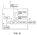
- Figure 3 illustrates a structure of a motor control circuit for actuating the sheet feeding motor for rotating the sheet feeding roller 2.
- Designated by 15 is a sheet feeding motor (stepping motor) for rotating the sheet feeding roller 2.
- Designated by 1b is a CPU, which is control means, disposed on the main board 1, for controlling the entirety of the recording apparatus and for controlling the sheet returning operation of the returning claw 9; designated by 1c is a motor driver for controlling the sheet feeding motor 15; ld is a RAM, for storing a temporary constant, designated by 1e is an EEPROM for storing operational parameters of the recording device 20 such as a control table for the motor 15 or the like.
- Designated by 14 is an internal or external host computer, which supplies recording instructions to the CPU.
- the CPU makes discrimination as to whether or not the instructions are for the first sheet. If so, the returning claw 9 is at the perpendicular position, that is, the returning claw 9 is substantially perpendicular relative to the separation pad 7a, and therefore, the motor driver lc causes the sheet feeding motor 15 to rotate in the forward direction to rotate the sheet feeding roller 2 in the forward direction. Then, the returning claw 9 is moved to the sheet feeding position (horizontal position as shown in Figure 2).
- the returning claw 9 this move to the sheet feeding position to enable the sheet to be fed out, and the sheet feeding motor 15 continues to rotate in the forward direction, by which the beating of the sheet by the sheet feeding roller 2 is started.
- the sheet feeding roller 2 is rotated in this manner, the contact between the cam portion and the hopper 3 is released so that hopper 3 is urged by the press-contact spring 4 toward the sheet feeding roller 2.
- the rotating sheet feeding roller 2 feeds several top ones of the sheets to the separation pad portion 7.
- the leading-edges of the stacked sheets are generally abutted to the rear wall 7d of the separation pad portion 7 show in Figure 1, and the several sheets are fed out from such positions.
- the sensor flag 2c is also rotated together with the rotation of the sheet feeding roller 2 so that output of the sheet feeding roller sensor la changes from "on” to "off".
- the CPU 1b uses the position where the output of the sensor changes as a starting point of the amount of operation of the roller rotation.
- the fed sheet reaches the nip for between the sheet feeding roller 2 and the separation pad 7a, at which the sheet subsequent to the topmost one of the sheets are stopped by the separation pad 7a at their leading-edges, so that only the topmost sheet is singled out while the leading-edge portions are forming into a wedge and is fed to bottom left direction in Figure 1.
- the returning claw 9 is pushed by the leading-edge of the sheet to be rotated in the couterclockwise direction so as not to obstruct the motion of the sheet.
- the leading-edge of the topmost sheet thus singled out reaches the actuator 10 and rotates the actuator 10.
- the end portion of the actuator 10 is out of the light blocking portion of the sheet end sensor lf, by which the sheet end sensor 1f can detect the leading-edge of the sheet.
- the inclination of the sheet is corrected by the pair 11 of feeding rollers.
- the CPU uses the detection signal from the sheet end sensor lf as the starting point of the operation amount or the distance through which the sheet is fed to the pair 11 of feeding roller as and is fed further enough to form a loop of sheet in contact with the pair 11 of feeding rollers.
- the sheet feeding roller 2 further rotates, the leading-edge of the sheet fed into the recording device is brought into abutment to the nip formed by the feeding rollers 11.
- the sheet is further fed through 3mm approx. for inclination correction to form a loop.
- the rotation of the motor temporarily stops. The distance through which the sheet is fed until this point of time is constant from the free end detection of the sheet as described hereinbefore.
- the pair 11 of feeding roller and sheet feeding roller 2 start to rotate at the same peripheral speeds, and immediately thereafter, the leading-edge of the sheet is fed between the feeding rollers 11. Furthermore, an unshown cam of the sheet feeding roller 2 lowers the hopper 3 so that sheet feeding roller 2 stops in the state shown in Figure 1, by which the sheet beating operation ends. At this time, the sheet feeding roller 2 is stopped on the basis of the starting point determined by actuation of the flag of the sheet feeding roller sensor la. The stopping operation may be based on the deactuation of the rotation starting flag.
- the sheet is further fed toward downstream by the pair 11 of feeding rollers driven by an unshown driving source, so that sheet pops out partially, and simultaneously there with, the printing its effected on the sheet by the recording head 13a.
- the recording position at this time is controlled by the distance of feed by the pair 11 of feeding roller after the abutment to the feeding roller.
- the sheet or sheets other than the topmost sheet are going to be moved by the friction relative to the topmost sheet, but the leading-edge thereof is stopped by the press-contact portion (stop position) between the roller 6 and the separation pad 7a, and therefore, it or they are not fed further.
- the generation of double feeding can be prevented.
- the returning claw 9 functions to return the rest of the sheets to prevent such a double feeding.
- the recording is effected on plain paper, for example, the separation is relatively stable, and the number of sheets is large. Therefore, the priorities placed on the recording speed to reduce the number of time-consuming sheet returning operations, to once per seven sheets, for example.
- the recording is effected on the other sheets, such as special paper, the frequency of the sheet returning operations with increased to once per one sheet, for example.
- the sheet feeding roller 2 is rotated through approx. 90° in the backward direction (reversed), after the trailing edge of the previous sheet is away from the separation pad portion 7 and the sheet end detection sensor lf detects the trailing edge of the previous sheet.
- the returning claw 9 takes a horizontal position (sheet feeding position) as shown in Figure 2, in which it is in the recess 2c of the cam portion 2d of the returning claw of the sheet feeding roller 2.
- the returning claw 9 is abutted to the left-hand end portion 2f of the recess 2e, so that returning claw 9 rotates in the clockwise direction.
- the position of the leading-edge of the sheet is reset, thus establishing the state in which the double feeding does not easily occur, only then the sheet feeding is started.
- the separation pad 7 and the roller 6 are spaced apart at proper timing so as to avoid that unshown cam or the like obstruct the sheet returning operation.
- the sheet feeding it started when the leading-edge of the sheet is in the neighborhood of the roller 6.
- the sheet other than the topmost sheet may passes through the nip formed between the roller 6 and the separation pad 7a for some reason or another. If it occurs, the double feeding is likely to occur.
- the sheet returning operation is carried out not at the predetermined timing of the sheet returning operations, if the sheet other than the topmost sheet passes through the nip between the roller 6 and the separation pad 7a, and the event is detected.
- the event is discriminated from the timing of the detection of the sheet leading-edge by the sheet end sensor 1f.
- the leading edge of the sheet is in the neighborhood of the rear wall 7d of the separation pad 7a, and therefore, the sheet reaches the sheet end sensor lf by feeding through a distance A from the start of the feeding of the sheet feeding roller 2, as shown in Figure 2.
- the feeding operation is started with the leading edge of the sheet being at the neighborhood of the roller 6, therefore, the leading edge of the sheet reaches the sheet end sensor lf by feeding only through a distance B.
- the position of the leading edge of the sheet before the sheet feeding can be detected.
- the double feeding tends to occur when the sheet exceeds the roller 6.
- the sheet returning operation is carried out before the start of the next sheet feeding, even when it is not the timing of the predetermined sheet returning operation.
- the timing at which the leading edge of the sheet reaches the sheet end sensor lf can be detected by detecting the number of the steps from the start of the rotation of the sheet feeding roller 2.
- the position (angle) of the start of the rotation of the sheet feeding roller 2 is not construct, the accurate control is accomplished by detecting the number of steps with the start point being at the sheet feeding roller sensor la.
- the topmost sheet and a part of the rest of the sheets may be passed through the nip formed between the roller 6 and the separation pad 7a (double feed) for some reason or another.
- the double feeding is discriminated by detecting the length of the sheet.
- the sheet length is detected by detecting the leading-edge and trailing-edge of the sheet.
- the occurrence of the double feed can be detected on the basis of the comparison between the sheet length thus detected and the data relating to the sheet length stored in the RAM ld which is initial storing means, the data having been supplied from the host computer, for example.
- the sheet returning sheet returning operation is carried out before the feet of the next sheet, in order to prevent the occurrence of the double feed upon the next sheet feeding.
- the registration is accomplished by abutting the leading edge of the sheet to the nip formed between the feeding rollers which are at rest. Therefore, the measured length (E) is a sum of the feeding length (operation distance) of the pair 11 of feeding rollers from the leading edge of the sheet abutting the nip formed between the feeding rollers 11 after the sheet end sensor lf detecting the leading edge of the sheet, to the sheet end sensor lf detecting the trailing edge of the sheet, and a distance between the sheet end sensor lf and the nip between the feeding rollers.
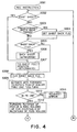
- the CPU lb When the host computer 14 produces recording instructions to CPU 1b (S301), the CPU lb first discriminates whether destructions are for the first sheet or not (S302). If the instructions are for the first sheet (Y in S302), the motor driver lc rotates the sheet feeding motor 15 in the forward direction to move the returning claw 9 to the sheet feeding position shown in Figure 1.
- the sheet returning requesting flag is cleared (S308), and the sheet feeding motor 15 is further rotated in the forward direction to rotate the sheet feeding roller 2 through one full-turn.
- the sheet feeding operation is started so that topmost one of the sheets is fed to the separation pad portion 7.
- the leading edge of the sheet stacked at this time is abutted to the rear wall 7d of the separation pad portion 7, and the sheet begins to be fed from that position.
- the sensor flag rotates with the rotation of the sheet feeding roller by which the output of the sheet feeding roller sensor la changes from OFF state to ON state.
- the feeding thus fed out reaches the nip formed between the sheet feeding roller 2 and the separation pad 7a, the sheets below the topmost sheet are stopped by the separation pad so that leading-edge portions of the rest sheets form into a wedge, and finally only the topmost sheet is singled out and fed to the downstream.
- the leading edge of the sheet reaches the actuator 10, so that actuator 10 is rotated, and the sheet end sensor lf detects the leading-edge of the sheet. That is, the sheet end sensor lf is actuated, that is, becomes "on" (S310). If the sheet end sensor lf is not actuated (N in S310), no sheet is discriminated, and error clearance operation is carried out.
- the pair 11 of feeding roller and sheet feeding roller 2 start to rotate at the same peripheral speeds (S312), and immediately thereafter, the leading-edge of the sheet is fed between the feeding rollers 11. Furthermore, an unshown cam of the sheet feeding roller 2 lowers the hopper 3 so that sheet feeding roller 2 stops in the state shown in Figure 1, by which the sheet beating operation ends. At this time, the sheet feeding roller 2 is stopped on the basis of the starting point determined by actuation of the flag of the sheet feeding roller sensor la.
- the sheet fed into the recording device is fed by the feeding rollers 11 driven by an unshown driving source so that sheet pops out partially (S313), and simultaneously therewith, the recording is effected on a sheet by the recording head 13a. After the recording operation thereon, the sheet is discharged. At this time, the sheet end sensor (PE) becomes "off", upon which the jam occurrence is checked (S315).
- the discrimination is made as to whether or not it is predetermined sheet returning timing, more particularly, whether or not it is the seventh sheet (S303) in this embodiment. If so (Y in S303), the sheet returning requesting flag is set (S304).
- the sheet feeding motor 15 is rotated reversely through the motor driver lc, so that returning claw 9 is moved from the sheet feeding position shown in Figure 1 to the claw returning position.
- the feeding distance D from the "OFF" state of the sheet feeding roller sensor la to the "ON" state of the sheet end sensor is detected by the number of steps of the sheet feeding motor 15. If the distance D is not more than B (PE discrimination value) (Y in S316), it is deemed that likelihood of double feeding is high, and therefore, the sheet returning requesting flag is set (S317).
- the comparison is made between the data relating to the sheet length supplied from the host computer and the actual measured length E of the sheet, and if the actually measured length E is longer than the sheet length data supplied from the host computer (set sheet length) plus ⁇ (Y in S3218), it is discriminated that double feeding has occurred, and the sheet returning requesting flag is set (S319).
- the sheet returning operation is carried out before the feeding of the next sheet, irrespective of whether or not the next is the predetermined timing for the sheet returning operation (S306).
- the sheet returning operation is carried out. By doing so, the number of sheet returning operations can be reduced without losing the desirable sheet feeding performance. In other words, the double feed can be avoided without losing the sheet feeding speed.
- the timing at which the sheet starts to move is different depending on the amount of the sheet stacked. That is, when the stacked amount is large, the sheet start to move quickly, and when the stack amount is small, the start of sheet movement is late. This is different depending on the profile of the cam. In the system in which the cam gradually raises the hopper, the timing at which the rubber and the sheet are contacted is different. When the timing of start of the sheet is different, the sheet end detection timing is different.
- the use can be made with a constant discrimination value.
- the detecting timing of the leading edge of the sheet upon the immediately previous sheet returning operation (A value) is stored, and the discrimination is made on the basis of B (proper margin should be added) provided by deducting C shown in Figure 2 therefrom.
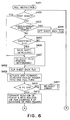
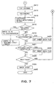
- FIGS 6 and 7 are flow chart of a sheet feeding operation in a recording device which is an example of the image forming apparatus according to a second embodiment of the present invention.
- steps S401-S415 and S419-S425 are the same as steps S301-S315 and S316-S322 of Figures 4 and 5.
- the sheet free end detection timing at the time of the immediately previous sheet returning operation after the sheet discharge (S415) is stored (A), and B (proper margin is added) provided by deducting C shown in Figure 2 therefrom is stored as "PE discrimination value" (S417).
- the double feeding does not tended to occur, that is, the sheet tends to be fed correctly.
- the data E corresponding to the measured sheet length upon the latest sheet returning operation is stored as "supposed sheet length" in the RAM ld which functions as sheet length storing means.
- the liability of the double feeding may be detected on the basis of comparison between the detecting timing of the leading-edge of the sheet after the separating operation and detecting timing of the leading-edge of the sheet after the separating operation after the previous sheet returning stored in the RAM ld. By doing so, the detection error attributable to the difference in the stack amount can be avoided by a simple structure.
- the double feeding may be detected by comparison between the supposed sheet length and the actually measured sheet length.
- the sheet length data to be provided from the host computer or the like are not necessarily.
- the data supplied from the host computer are related with the sheet length, but the present invention is not limited to this example, and the data supplied from the host computer may be the recording range data which corresponds to the length not including the front and rear margins. In such a case, the actually measured sheet length should not include the margins.
- the recording range which is counted as a value required for the recording may be measured, and the measurement may be used.
- the position of the leading edge of the sheet in the measured length is on the basis of the leading-edge detection by the sheet end sensor lf.
- the structure for the comparison between the measured sheet length and the supposed sheet length is the same.
- the machine detects and sets the size of the sheets set in the apparatus, and in such a case, the data may be used for the supposed sheet length.
- the sheet returning operation is carried out on the basis of the detection of the leading edge of the sheet before the start of sheet feeding, by the sheet end detection sensor lf.
- a sensor exclusively for detection of the presence or absence of the sheet slightly downstream of the roller 6, and when the sensor detects the presence of the sheet before the sheet feeding, the sheet returning may be carried out before the next sheet feeding.
- the similar advantageous effects can be provided irrespective of the separating type, if the sheet returning operation can be selectively carried out, and the detection timing of the leading edge of the sheet and the detection of the sheet length are possible.
- the sheet feeding it started only by the rotation of the sheet feeding motor 15, but the present invention is applicable to the structure in which they use is made with a latch for permitting one full rotation in the fourth direction by a small backward rotation.
- the separation of the sheet feeding roller 2 and the sheet, the feeding of the sheet are completed through one full rotation of the sheet feeding roller 2, but the present invention is not limited to such examples.
- they use can be made with a circular roller and a hopper raising and lowering mechanism which are driven to separately.
- the similar control operations are carried out at the timing of detection of the leading edge of the sheet on the basis of the rising over the hopper. By doing so, the similar advantageous effects are provided.
- the structure relating to the sheet length is applicable irrespective of the structure of the separating portions.
- the sheet feeding roller 2 and the feeding rollers are driven by different motors, but they may be driven by the same motors.
- the motors used in the foregoing embodiments are stepping motors, but other types of motors are usable if the feeding distance can be detected.
- An example of such motors are a combination of a DC motor and an encoder.
- the returning means is operated to carry out the sheet returning operation when the position of the leading edge of the sheet other than the sheet single out by the separating means is downstream of the stop position of the separating means.
- the rest of the sheets can be returned to the sheet stacking means, thereby to avoid the double feeding, without losing the sheet feeding speed.
- a sheet feeding apparatus includes sheet stacking means for stacking sheets; sheet feeding means for feeding the sheets from the sheet stacking means; separating means for separating for separating the sheets one by one; returning means for returning the sheet other than the sheet separated by separating means toward the sheet stacking means; wherein the returning means effects its sheet returning operation when the sheet other than the sheet separated from the separating means passes through a predetermined position.
Landscapes
- Engineering & Computer Science (AREA)
- Mechanical Engineering (AREA)
- Sheets, Magazines, And Separation Thereof (AREA)
- Photographic Developing Apparatuses (AREA)
- Fixing For Electrophotography (AREA)
- Unwinding Webs (AREA)
Abstract
Description
- The present invention relates to a sheet feeding apparatus and an image forming apparatus provided with the same, and more particularly to a sheet feeding apparatus having a sheet returning mechanism for preventing double feeding of sheets, and an image forming apparatus provided with such a sheet feeding apparatus.
- Heretofore, an image forming apparatus such as a printer or the like is provided with a sheet feeding apparatus for feeding in seriatim the sheets to an image formation station such as a recording station. In such a sheet feeding apparatus, a sheet feeding roller is press-contacted to the sheet to impart a feeding force, while on the other hand separating means including a separation pad, a separation claw, a separation bank or the like imparts a load against the feeding, by which the sheet is singled out with the subsequent sheets left.
- In a known example of such a sheet feeding apparatus, after the sheet separating action, the additional sheet or sheets fed out unintentionally are returned to the sheet stacking portion from which the sheet or sheets have been fed out, while aligning the leading-edge or edges with the rest of the sheets therein (sheet returning mechanism). For the purpose of compatibility between the separation performance and the sheet feeding speed, the sheet returning operations are effected periodically (selectively), in other words, they are effected each time a predetermined number of sheets are fed out.
- In a prior art device of such a structure, the sheet returning operations are carried out periodically even though the number of sheet returning operations may be changed depending on selections of printing modes. In order to assure the prevention of the double feeding despite variations depending on the differences of the sheet materials, printing modes, operating environment, it is required to determine the number of sheet returning operations with an ample margin.
- With the ample margin, the sheet feeding speed has to be decreased. Additionally, when the periodical sheet returning operations are employed, occurrence of double feeding attributable to an unexpected cause cannot be avoided.
- Accordingly, it is a principal object of the present invention to provide a sheet feeding apparatus and an image forming apparatus provided with the same, wherein the double feeding can be avoided.
- According to an aspect of the present invention, there is provided a sheet feeding apparatus comprising sheet stacking means for stacking sheets; sheet feeding means for feeding the sheets from said sheet stacking means; separating means for separating for separating the sheets one by one; returning means for returning the sheet other than the sheet separated by separating means toward said sheet stacking means; wherein said returning means effects its sheet returning operation when the sheet other than the sheet separated from said separating means passes through a predetermined position.
- According to another aspect of the present invention, there is provided a sheet feeding apparatus comprising sheet stacking means for stacking sheets sheet feeding means for feeding the sheets from said sheet stacking means; separating means for separating for separating the sheets one by one; returning means for returning the sheet other than the sheet separated by separating means toward said sheet stacking means; sheet end detecting means for detecting a leading-edge and a trailing-edge of the sheet separated by said separating means; wherein a sheet returning operation is carried out by said returning means in accordance with a length of the sheet calculated by said sheet end detecting means.
- These and other objects, features and advantages of the present invention will become more apparent upon a consideration of the following description of the preferred embodiments of the present invention taken in conjunction with the accompanying drawings.
-
- Figure 1 is a schematic sectional view of a recording device according to a first embodiment of the present invention.
- Figure 2 is a schematic sectional view of the recording device.
- Figure 3 is a control block diagram of the recording apparatus.
- Figure 4 is a flow chart of a part of a recording operation control of the recording device.
- Figure 5 is a flow chart of a part of a recording operation control of the recording device.
- Figure 6 is a flow chart of a part of a recording operation control of a recording device according to a second embodiment of the present invention.
- Figure 7 is a flow chart of a part of a recording operation control of the recording device.
-
- Figure 1 is a schematic sectional view of a recording device according to an exemplary image forming apparatus, and Figure 2 is a schematic sectional view of the recording device. In Figure 1, designated by 20 is a recording device which comprises a
recording head unit 13 which is an image formation station having arecording head 13a, asheet feeding apparatus 21 for feeding an unshown sheet to a position facing to therecording head unit 13, amain board 1 or the like for controlling the entire recording device. - Here, the
sheet feeding apparatus 21 comprises asheet feeding roller 2 which has a half-moon cross-section and which functions as sheet feeding means for picking up the sheet stepped on an unshown sheet stacking portion; ahopper 3 for press-contacting the sheet to thesheet feeding roller 2; and apad portion 7 having aseparation pad 7a which is separating means for separating the sheet picked up by thesheet feeding roller 2. - The
sheet feeding roller 2 has aroller rubber 2a contactable to the surface of the sheet, aroller shaft 2b providing a center of rotation, asensor flag 2c for blocking a transparent type sheet feeding roller sensor la which functions as position detecting means provided on amain board 1 to detect a position of thesheet feeding roller 2, and an unshown cam perform lowering thehopper 3. They are rotatable altogether about the axis of theroller shaft 2b. - The
hopper 3 is movable in interrelation with rotation of thesheet feeding roller 2 toward and away from thesheet feeding roller 2, so that sheet is press-contacted to thesheet feeding roller 2 by the elastic force of the press-contact spring 4 only when an arcuate portion of theroller rubber 2a is faced to the sheet. The motion of thehopper 3 toward and away from thesheet feeding roller 2 is effected by the cooperation of the cam of thesheet feeding roller 2 and the press-contact spring 4. - Designated by a
reference numeral 5 is a base rotatably supporting thehopper 3 through ashaft 3a. Designated byreference numeral 8 is a separation base supported for movement in a direction perpendicular to a sheet fitting direction (widthwise direction of the sheet). Theseparation pad portion 7 is mounted on theseparation base 8 for pivoting motion about an axis of arotational shaft 7b. Designated by 7c is a separation pad spring which functions to urge theseparation pad portion 7 toward thesheet feeding roller 2. - Figure 1 shows the state in which the sheet is being picked up. In the state, the flat surface portion of the
sheet feeding roller 2 and theseparation pad 7a are substantially parallel with each other, and theseparation pad 7a is retained away from thesheet feeding roller 2 by an unshown stopper portion. Only a neighborhood of a circumferential portion of thesheet feeding roller 2 is about the date to theseparation pad 7a. - Designated by a
reference numeral 6 is a roller providing a stock position at which the sheet is stopped, by abutment to theseparation pad 7a. Theroller 6 is provided at a position deviated from the position of thesheet feeding roller 2 in the widthwise direction of the sheet, and is pressed against theseparation pad 7a by an unshown spring so lightly that rotation thereof is not disturbed. By the light pressing of theroller 6 to theseparation pad 7a, the second and subsequent sheets which tend to move together with the sheet intended to feed out, are constrained by theseparation pad 7a. - In Figure 2,
reference numeral 9 designate a returning claw (sheet returning means). The returningclaw 9 is disposed at a position which is deviated from the position of thesheet feeding roller 2 and from the position of theroller 6 in the widthwise direction of the sheet, and is rotatably supported on theseparation base 8 through therotational shaft 9a. The returningclaw 9, when the sheet is fed, is in a horizontal position as shown in Figure 2. However, when the sheet returning action is effected and when the sheet feeding spouts, it is retained at the position substantially perpendicular to theseparation pad 7a by unshown spring and stopper. - In Figure 2, designated by 2d is a returning claw cam portion which is disposed at a side of the
sheet feeding roller 2 and which is provided with arecess 2e formed therein. When the returningclaw 9 takes a position substantially perpendicular relative to theseparation pad 7a, that is, the sheet returning action is to be carried out, or before the start of the sheet feeding, the free end portion of the returningclaw 9 enters therecess 2e. - Designated by 11 is a pair of feeding rollers which is feeding means for feeding the picked-up sheet, and 12 is a pair of sheet discharging rollers for discharging the sheet on which the image is printed, out of the apparatus. Designated by 1f is a sheet end sensor of a transparent type (PE sensor) which is provided on the main board and which functions as sheet end detecting means for detecting a leading end of the sheet, and designated by 10 is an actuator which is pushed by the sheet which is being fed. The
sheet end sensor 1f detects the leading end and trading end of the sheet by rotation of theactuator 10. - Figure 3 illustrates a structure of a motor control circuit for actuating the sheet feeding motor for rotating the
sheet feeding roller 2. Designated by 15 is a sheet feeding motor (stepping motor) for rotating thesheet feeding roller 2. - Designated by 1b is a CPU, which is control means, disposed on the
main board 1, for controlling the entirety of the recording apparatus and for controlling the sheet returning operation of the returningclaw 9; designated by 1c is a motor driver for controlling thesheet feeding motor 15; ld is a RAM, for storing a temporary constant, designated by 1e is an EEPROM for storing operational parameters of therecording device 20 such as a control table for themotor 15 or the like. - Designated by 14 is an internal or external host computer, which supplies recording instructions to the CPU.
- The description will be made as to a normal sheet feeding operation in the above-described
recording device 20. - When the recording instructions is fed to the CPU from the
host computer 14, the CPU makes discrimination as to whether or not the instructions are for the first sheet. If so, the returningclaw 9 is at the perpendicular position, that is, the returningclaw 9 is substantially perpendicular relative to theseparation pad 7a, and therefore, the motor driver lc causes thesheet feeding motor 15 to rotate in the forward direction to rotate thesheet feeding roller 2 in the forward direction. Then, the returningclaw 9 is moved to the sheet feeding position (horizontal position as shown in Figure 2). - Then, the returning
claw 9 this move to the sheet feeding position to enable the sheet to be fed out, and thesheet feeding motor 15 continues to rotate in the forward direction, by which the beating of the sheet by thesheet feeding roller 2 is started. When thesheet feeding roller 2 is rotated in this manner, the contact between the cam portion and thehopper 3 is released so thathopper 3 is urged by the press-contact spring 4 toward thesheet feeding roller 2. In this state, the rotatingsheet feeding roller 2 feeds several top ones of the sheets to theseparation pad portion 7. - Here, the leading-edges of the stacked sheets are generally abutted to the
rear wall 7d of theseparation pad portion 7 show in Figure 1, and the several sheets are fed out from such positions. Add this time, thesensor flag 2c is also rotated together with the rotation of thesheet feeding roller 2 so that output of the sheet feeding roller sensor la changes from "on" to "off". TheCPU 1b uses the position where the output of the sensor changes as a starting point of the amount of operation of the roller rotation. - On the other hand, the fed sheet reaches the nip for between the
sheet feeding roller 2 and theseparation pad 7a, at which the sheet subsequent to the topmost one of the sheets are stopped by theseparation pad 7a at their leading-edges, so that only the topmost sheet is singled out while the leading-edge portions are forming into a wedge and is fed to bottom left direction in Figure 1. At this time, the returningclaw 9 is pushed by the leading-edge of the sheet to be rotated in the couterclockwise direction so as not to obstruct the motion of the sheet. - Then, the leading-edge of the topmost sheet thus singled out reaches the
actuator 10 and rotates theactuator 10. With this, the end portion of theactuator 10 is out of the light blocking portion of the sheet end sensor lf, by which thesheet end sensor 1f can detect the leading-edge of the sheet. - In this embodiment, the inclination of the sheet is corrected by the
pair 11 of feeding rollers. The CPU uses the detection signal from the sheet end sensor lf as the starting point of the operation amount or the distance through which the sheet is fed to thepair 11 of feeding roller as and is fed further enough to form a loop of sheet in contact with thepair 11 of feeding rollers. Thus, when thesheet feeding roller 2 further rotates, the leading-edge of the sheet fed into the recording device is brought into abutment to the nip formed by the feedingrollers 11. The sheet is further fed through 3mm approx. for inclination correction to form a loop. Then, the rotation of the motor temporarily stops. The distance through which the sheet is fed until this point of time is constant from the free end detection of the sheet as described hereinbefore. - Then, the
pair 11 of feeding roller andsheet feeding roller 2 start to rotate at the same peripheral speeds, and immediately thereafter, the leading-edge of the sheet is fed between the feedingrollers 11. Furthermore, an unshown cam of thesheet feeding roller 2 lowers thehopper 3 so thatsheet feeding roller 2 stops in the state shown in Figure 1, by which the sheet beating operation ends. At this time, thesheet feeding roller 2 is stopped on the basis of the starting point determined by actuation of the flag of the sheet feeding roller sensor la. The stopping operation may be based on the deactuation of the rotation starting flag. - Thereafter, the sheet is further fed toward downstream by the
pair 11 of feeding rollers driven by an unshown driving source, so that sheet pops out partially, and simultaneously there with, the printing its effected on the sheet by therecording head 13a. The recording position at this time is controlled by the distance of feed by thepair 11 of feeding roller after the abutment to the feeding roller. - During the operation, the sheet or sheets other than the topmost sheet are going to be moved by the friction relative to the topmost sheet, but the leading-edge thereof is stopped by the press-contact portion (stop position) between the
roller 6 and theseparation pad 7a, and therefore, it or they are not fed further. Thus, the generation of double feeding can be prevented. - However, if a sheet or sheets other than the topmost sheet are passed through the press-contact portion (stop position) between the
roller 6 and theseparation pad 7a for some reason or another (particularly, more than two sheets), there exists nothing functioning to constrain the sheets, with the result that double feeding occurs due to the friction between the topmost sheet and the rest. Once this occurs, theroller 6 is raised by the sheet, with the result of increase of the number of sheets passing through the nip. - Therefore, when the recording operation is carried out on two or more sheets, the returning
claw 9 functions to return the rest of the sheets to prevent such a double feeding. When, however, the recording is effected on plain paper, for example, the separation is relatively stable, and the number of sheets is large. Therefore, the priorities placed on the recording speed to reduce the number of time-consuming sheet returning operations, to once per seven sheets, for example. When the recording is effected on the other sheets, such as special paper, the frequency of the sheet returning operations with increased to once per one sheet, for example. - The description will be made as to the operation of the sheet returning when the recording operation is effected continuously on two or more sheets.
- When the sheet returning operation is carried out, the
sheet feeding roller 2 is rotated through approx. 90° in the backward direction (reversed), after the trailing edge of the previous sheet is away from theseparation pad portion 7 and the sheet end detection sensor lf detects the trailing edge of the previous sheet. At this time, there is no sheet on the returningclaw 9, and therefore, the returningclaw 9 takes a horizontal position (sheet feeding position) as shown in Figure 2, in which it is in therecess 2c of thecam portion 2d of the returning claw of thesheet feeding roller 2. The, when thesheet feeding roller 2 rotates in the backward direction, the returningclaw 9 is abutted to the left-hand end portion 2f of therecess 2e, so that returningclaw 9 rotates in the clockwise direction. When the returningclaw 9 rotates in the clockwise direction, the returningclaw 9 becomes substantially perpendicular to theseparation pad 7a, and therefore, the sheet which is confined by theroller 6 is pushed back to such an extent that the leading-edge thereof almost abuts therear wall 7d of theseparation pad 7a. - This, the position of the leading-edge of the sheet is reset, thus establishing the state in which the double feeding does not easily occur, only then the sheet feeding is started. At this time, the
separation pad 7 and theroller 6 are spaced apart at proper timing so as to avoid that unshown cam or the like obstruct the sheet returning operation. - On the other hand, when the recording is effected on plain paper or the like, and the sheet returning operation is not carried out, the sheet feeding it started when the leading-edge of the sheet is in the neighborhood of the
roller 6. After the sheet returning operation is carried out, the sheet other than the topmost sheet may passes through the nip formed between theroller 6 and theseparation pad 7a for some reason or another. If it occurs, the double feeding is likely to occur. - In view of this, in this embodiment, the sheet returning operation is carried out not at the predetermined timing of the sheet returning operations, if the sheet other than the topmost sheet passes through the nip between the
roller 6 and theseparation pad 7a, and the event is detected. - In this embodiment, the event is discriminated from the timing of the detection of the sheet leading-edge by the
sheet end sensor 1f. - The description will be made as to the detection of the leading-edge of the sheet.
- Normally, upon the sheet beating after the sheet set and the operation of the sheet returning, the leading edge of the sheet is in the neighborhood of the
rear wall 7d of theseparation pad 7a, and therefore, the sheet reaches the sheet end sensor lf by feeding through a distance A from the start of the feeding of thesheet feeding roller 2, as shown in Figure 2.On the other hand, when the sheet returning operation is not carried out, the feeding operation is started with the leading edge of the sheet being at the neighborhood of theroller 6, therefore, the leading edge of the sheet reaches the sheet end sensor lf by feeding only through a distance B. - Therefore, by detecting the timing of the leading edge of the sheet reaching the sheet end sensor lf, the position of the leading edge of the sheet before the sheet feeding can be detected. In the system as in this embodiment, the double feeding tends to occur when the sheet exceeds the
roller 6. In view of this, it is deemed that double feeding is likely to occur when the detected value is not more than B (with proper margin. In this case, the sheet returning operation is carried out before the start of the next sheet feeding, even when it is not the timing of the predetermined sheet returning operation. By detecting the position of the leading edge of the sheet before the feeding in this manner, the likelihood of the double feeding can be predicted. - More particularly, assuming that position (angle) and of the start of rotation of the
sheet feeding roller 2, the timing at which the leading edge of the sheet reaches the sheet end sensor lf can be detected by detecting the number of the steps from the start of the rotation of thesheet feeding roller 2. When the position (angle) of the start of the rotation of thesheet feeding roller 2 is not construct, the accurate control is accomplished by detecting the number of steps with the start point being at the sheet feeding roller sensor la. - On the other hand, the topmost sheet and a part of the rest of the sheets may be passed through the nip formed between the
roller 6 and theseparation pad 7a (double feed) for some reason or another. In such a case, the double feeding is discriminated by detecting the length of the sheet. - In this embodiment, the sheet length is detected by detecting the leading-edge and trailing-edge of the sheet. The occurrence of the double feed can be detected on the basis of the comparison between the sheet length thus detected and the data relating to the sheet length stored in the RAM ld which is initial storing means, the data having been supplied from the host computer, for example. When the double feed occurrence is detected, the sheet returning sheet returning operation is carried out before the feet of the next sheet, in order to prevent the occurrence of the double feed upon the next sheet feeding.
- In this embodiment, the registration is accomplished by abutting the leading edge of the sheet to the nip formed between the feeding rollers which are at rest. Therefore, the measured length (E) is a sum of the feeding length (operation distance) of the
pair 11 of feeding rollers from the leading edge of the sheet abutting the nip formed between the feedingrollers 11 after the sheet end sensor lf detecting the leading edge of the sheet, to the sheet end sensor lf detecting the trailing edge of the sheet, and a distance between the sheet end sensor lf and the nip between the feeding rollers. - Referring to Figures 4 and 5, the description will be made as to sheet feeding operation of the
recording device 20 of such structures. - When the
host computer 14 produces recording instructions toCPU 1b (S301), the CPU lb first discriminates whether destructions are for the first sheet or not (S302). If the instructions are for the first sheet (Y in S302), the motor driver lc rotates thesheet feeding motor 15 in the forward direction to move the returningclaw 9 to the sheet feeding position shown in Figure 1. - Subsequently, the sheet returning requesting flag is cleared (S308), and the
sheet feeding motor 15 is further rotated in the forward direction to rotate thesheet feeding roller 2 through one full-turn. By doing so, the sheet feeding operation is started so that topmost one of the sheets is fed to theseparation pad portion 7. The leading edge of the sheet stacked at this time is abutted to therear wall 7d of theseparation pad portion 7, and the sheet begins to be fed from that position. In this case, the sensor flag rotates with the rotation of the sheet feeding roller by which the output of the sheet feeding roller sensor la changes from OFF state to ON state. - The feeding thus fed out reaches the nip formed between the
sheet feeding roller 2 and theseparation pad 7a, the sheets below the topmost sheet are stopped by the separation pad so that leading-edge portions of the rest sheets form into a wedge, and finally only the topmost sheet is singled out and fed to the downstream. Then, the leading edge of the sheet reaches theactuator 10, so thatactuator 10 is rotated, and the sheet end sensor lf detects the leading-edge of the sheet. That is, the sheet end sensor lf is actuated, that is, becomes "on" (S310). If the sheet end sensor lf is not actuated (N in S310), no sheet is discriminated, and error clearance operation is carried out. - Thereafter, when the
sheet feeding roller 2 rotates further, the leading edge of the sheet fed into the recording apparatus is brought into abutment to the nip formed between the feedingrollers 11 which are at rest then, and the sheet is fed further through approx. 3mm to correct inclination of feeding, and then the rotation of the motor temporarily stops. - Then, the
pair 11 of feeding roller andsheet feeding roller 2 start to rotate at the same peripheral speeds (S312), and immediately thereafter, the leading-edge of the sheet is fed between the feedingrollers 11. Furthermore, an unshown cam of thesheet feeding roller 2 lowers thehopper 3 so thatsheet feeding roller 2 stops in the state shown in Figure 1, by which the sheet beating operation ends. At this time, thesheet feeding roller 2 is stopped on the basis of the starting point determined by actuation of the flag of the sheet feeding roller sensor la. - The sheet fed into the recording device is fed by the feeding
rollers 11 driven by an unshown driving source so that sheet pops out partially (S313), and simultaneously therewith, the recording is effected on a sheet by therecording head 13a. After the recording operation thereon, the sheet is discharged. At this time, the sheet end sensor (PE) becomes "off", upon which the jam occurrence is checked (S315). On the other hand, if the recording instructions have not for the first sheet (N in S302), the discrimination is made as to whether or not it is predetermined sheet returning timing, more particularly, whether or not it is the seventh sheet (S303) in this embodiment. If so (Y in S303), the sheet returning requesting flag is set (S304). When the setting of the sheet returning requesting flag is detected (Y in S305), thesheet feeding motor 15 is rotated reversely through the motor driver lc, so that returningclaw 9 is moved from the sheet feeding position shown in Figure 1 to the claw returning position. - Thereafter, the
sheet feeding motor 15 is rotated in the forward direction, the returningclaw 9 is returned to the sheet feeding position, and then, the sheet returning requesting flag is cleared (S308), and the operations of steps S309-S315 are carried out. - As described hereinbefore, after the sheep is discharged, the feeding distance D from the "OFF" state of the sheet feeding roller sensor la to the "ON" state of the sheet end sensor is detected by the number of steps of the
sheet feeding motor 15. If the distance D is not more than B (PE discrimination value) (Y in S316), it is deemed that likelihood of double feeding is high, and therefore, the sheet returning requesting flag is set (S317). - The comparison is made between the data relating to the sheet length supplied from the host computer and the actual measured length E of the sheet, and if the actually measured length E is longer than the sheet length data supplied from the host computer (set sheet length) plus α (Y in S3218), it is discriminated that double feeding has occurred, and the sheet returning requesting flag is set (S319).
- Then, with the sheet returning requesting flag set by the two space, if there are recording instructions for the next sheet (Y in S320), the sheet returning operation is carried out before the feeding of the next sheet, irrespective of whether or not the next is the predetermined timing for the sheet returning operation (S306).
- In this number, when the liability of the double feed is high or when the double feed is detected, the sheet returning operation is carried out. By doing so, the number of sheet returning operations can be reduced without losing the desirable sheet feeding performance. In other words, the double feed can be avoided without losing the sheet feeding speed.
- When the sheet delivery by the
sheet feeding roller 2 is started, the timing at which the sheet starts to move is different depending on the amount of the sheet stacked. That is, when the stacked amount is large, the sheet start to move quickly, and when the stack amount is small, the start of sheet movement is late. This is different depending on the profile of the cam. In the system in which the cam gradually raises the hopper, the timing at which the rubber and the sheet are contacted is different. When the timing of start of the sheet is different, the sheet end detection timing is different. - In view of this, the use can be made with a constant discrimination value. In a preferable alternative, the detecting timing of the leading edge of the sheet upon the immediately previous sheet returning operation (A value) is stored, and the discrimination is made on the basis of B (proper margin should be added) provided by deducting C shown in Figure 2 therefrom.
- Figures 6 and 7 are flow chart of a sheet feeding operation in a recording device which is an example of the image forming apparatus according to a second embodiment of the present invention. In this Figure, steps S401-S415 and S419-S425 are the same as steps S301-S315 and S316-S322 of Figures 4 and 5.
- In this embodiment, the sheet free end detection timing at the time of the immediately previous sheet returning operation after the sheet discharge (S415) is stored (A), and B (proper margin is added) provided by deducting C shown in Figure 2 therefrom is stored as "PE discrimination value" (S417).
- In this embodiment, the fact that immediately after the sheet returning operational, the double feeding does not tended to occur, that is, the sheet tends to be fed correctly. More particularly, the data E corresponding to the measured sheet length upon the latest sheet returning operation is stored as "supposed sheet length" in the RAM ld which functions as sheet length storing means. The liability of the double feeding may be detected on the basis of comparison between the detecting timing of the leading-edge of the sheet after the separating operation and detecting timing of the leading-edge of the sheet after the separating operation after the previous sheet returning stored in the RAM ld. By doing so, the detection error attributable to the difference in the stack amount can be avoided by a simple structure.
- In an alternative, the double feeding may be detected by comparison between the supposed sheet length and the actually measured sheet length. By doing so, the sheet length data to be provided from the host computer or the like are not necessarily.
- In the foregoing description, the data supplied from the host computer are related with the sheet length, but the present invention is not limited to this example, and the data supplied from the host computer may be the recording range data which corresponds to the length not including the front and rear margins. In such a case, the actually measured sheet length should not include the margins. Alternatively, the recording range which is counted as a value required for the recording may be measured, and the measurement may be used.
- In the foregoing, the description has been made as to the apparatus in which the leading edge of the sheet is abutted to the feeding rollers which are at rest to effect registration with image to be recorded. The same applies to the case in which the leading edge of the sheet is abutted to feeding rollers which are rotated in the opposite directions to effect the registration. In the apparatus in which no registering operation is carried out, the position of the leading edge of the sheet in the measured length is on the basis of the leading-edge detection by the sheet end sensor lf. The structure for the comparison between the measured sheet length and the supposed sheet length is the same.
- In the foregoing, the description has been made as to an example in which the supposed sheet length can be obtained from the host computer as the recording apparatus. However, in the case of stand-alone type machine such as a copying machine, the machine detects and sets the size of the sheets set in the apparatus, and in such a case, the data may be used for the supposed sheet length.
- In the foregoing, the sheet returning operation is carried out on the basis of the detection of the leading edge of the sheet before the start of sheet feeding, by the sheet end detection sensor lf. In an alternative, a sensor exclusively for detection of the presence or absence of the sheet slightly downstream of the
roller 6, and when the sensor detects the presence of the sheet before the sheet feeding, the sheet returning may be carried out before the next sheet feeding. - In the foregoing, the description has been made as to the friction separating type in which the use the spade with the half-moon roller and the roller for double feeding prevention, but the present invention is not limited to this example of the separation type. The similar advantageous effects can be provided irrespective of the separating type, if the sheet returning operation can be selectively carried out, and the detection timing of the leading edge of the sheet and the detection of the sheet length are possible. In the foregoing Embodiments, the sheet feeding it started only by the rotation of the
sheet feeding motor 15, but the present invention is applicable to the structure in which they use is made with a latch for permitting one full rotation in the fourth direction by a small backward rotation. - In the foregoing examples, the separation of the
sheet feeding roller 2 and the sheet, the feeding of the sheet are completed through one full rotation of thesheet feeding roller 2, but the present invention is not limited to such examples. For example, they use can be made with a circular roller and a hopper raising and lowering mechanism which are driven to separately. In this case, the similar control operations are carried out at the timing of detection of the leading edge of the sheet on the basis of the rising over the hopper. By doing so, the similar advantageous effects are provided. The structure relating to the sheet length is applicable irrespective of the structure of the separating portions. - In the foregoing embodiments, the
sheet feeding roller 2 and the feeding rollers are driven by different motors, but they may be driven by the same motors. The motors used in the foregoing embodiments are stepping motors, but other types of motors are usable if the feeding distance can be detected. An example of such motors are a combination of a DC motor and an encoder. - As described in the foregoing, according to embodiments, the returning means is operated to carry out the sheet returning operation when the position of the leading edge of the sheet other than the sheet single out by the separating means is downstream of the stop position of the separating means. Thus, the rest of the sheets can be returned to the sheet stacking means, thereby to avoid the double feeding, without losing the sheet feeding speed.
- A sheet feeding apparatus includes sheet stacking means for stacking sheets; sheet feeding means for feeding the sheets from the sheet stacking means; separating means for separating for separating the sheets one by one; returning means for returning the sheet other than the sheet separated by separating means toward the sheet stacking means; wherein the returning means effects its sheet returning operation when the sheet other than the sheet separated from the separating means passes through a predetermined position.
Claims (32)
- A sheet feeding apparatus comprising:wherein said returning means effects its sheet returning operation when the sheet other than the sheet separated from said separating means passes through a predetermined position.sheet stacking means for stacking sheets;sheet feeding means for feeding the sheets from said sheet stacking means;separating means for separating for separating the sheets one by one;returning means for returning the sheet other than the sheet separated by separating means toward said sheet stacking means;
- An apparatus according to Claim 1, further comprising sheet end detecting means for detecting a leading-edge of the sheet separated by said separating means, wherein it is discriminated in accordance with timing of detection of the leading edge of the sheet separated by said separating means by said sheet end detecting means whether or not the sheet other than the sheet separated by said separating means passes through the predetermined position.
- An apparatus according to Claim 2, wherein said sheet end detecting means detects an amount of operation of said sheet feeding means to detection of the leading edge of the sheet, it is discriminated on the basis of an output of said sheet end detecting means whether or not the sheet other than the sheet separated by said separating means passes through the predetermined position.
- An apparatus according to Claim 3, further comprising phase detecting means for detecting a phase of said sheet feeding means, and detection of the amount of the operation of said sheet feeding means is started on the basis of the information from said phase detecting means.
- An apparatus according to Claim 3, further comprising storing means for storing the amount of the operation of said sheet feeding means until said sheet end detecting means detects a free end of the sheet immediately after the sheet returning operation, it is discriminated whether or not the sheet other than the sheet separated by said separating means passes through the predetermined position, on the basis of a comparison between the amount of the operations of said sheet feeding means until said sheet end detecting means detects the leading edge of the sheet and an amount of operation stored in said storing means.
- An apparatus according to Claim 1, wherein said separating means is of a friction separating type and is provided with a friction element, and a roller for confining the leading edge of the sheet other than the sheet separated by said separating means, by contact to said separating means.
- An apparatus according to Claim 3, wherein said sheet feeding means is driven by a stepping motor, and the amount of the operation of said sheet feeding means is detected by number of pulses of the stepping motor.
- An apparatus according to Claim 3, wherein a driving system for said sheet feeding means includes an encoder, and the amount of the operation of said sheet feeding means is detected on the basis of a detected value of the encoder.
- A sheet feeding apparatus comprising:wherein a sheet returning operation is carried out by said returning means in accordance with a length of the sheet calculated by said sheet end detecting means.sheet stacking means for stacking sheets;sheet feeding means for feeding the sheets from said sheet stacking means;separating means for separating for separating the sheets one by one;returning means for returning the sheet other than the sheet separated by separating means toward said sheet stacking means;sheet end detecting means for detecting a leading-edge and a trailing-edge of the sheet separated by said separating means;
- An apparatus according to Claim 9, further comprising storing means for storing a length of the sheets stacked on said sheet stacking means, wherein it is discriminated on the basis of comparison between the length of the sheet calculated by said sheet end detecting means and the length of the sheet stored in said storing means whether the sheet returning operation by said returning means is to be carried out or not.
- An apparatus according to Claim 9, wherein the length of the sheet is calculated on the basis of the amount of operation of said sheet feeding means to detection of a trailing-edge of the sheet of said sheet end detecting means.
- An apparatus according to Claim 9, further comprising storing means for storing a length of the sheet immediately after a sheet returning operation of said returning means, wherein it is discriminated on the basis of comparison between the length of the sheet calculated by said sheet end detecting means and the length of the sheet stored in said storing means whether the sheet returning operation of said returning means is to be carried out or not.
- An apparatus according to Claim 9, wherein a driving source for said sheet feeding means is a stepping motor, wherein the length of the sheet is calculated on the basis of the number of pulses of the stepping motor.
- An apparatus according to Claim 9, further comprising an encoder in a driving system for said feeding means, wherein the length of the sheet is calculated on the basis of an output of the encoder.
- A sheet feeding apparatus comprising:wherein a sheet returning operation of said returning claw is carried out when the sheet other than the sheet separated by said separation portion passes through a predetermined position;.a sheet stacking portion for stacking sheets;a sheet feeding roller for feeding the sheets stacked on said sheet stacking portion;a separation portion for separating the sheets one by one;a returning claw for returning the sheet other than the sheet separated by said separation portion toward said sheet stacking portion;
- An apparatus according to Claim 15, further comprising a sheet end detection portion for detecting a leading-edge of the sheet separated by said returning claw, wherein it is discriminated in accordance with timing at which said sheet end detection portion detects the leading edge of the sheet separated by said separation portion whether the sheet other than the sheet separated by said separation portion passes through the predetermined position or not.
- An apparatus according to Claim 16, wherein an amount of operation of said sheet feeding roller to detection of the leading edge of the sheet by said detecting portion, and on the basis of the protection, it is discriminated whether the sheet other than the sheet separated by said separation portion passes through the predetermined position.
- An apparatus according to Claim 17, further comprising a phase detection portion for detecting a phase of said sheet feeding roller, wherein detection of the amount of the operation of said sheet feeding roller is started on the basis of information from said phase detection portion.
- An apparatus according to Claim 17, further comprising storing portion for storing an amount of operation of said sheet feeding roller to detection of the leading edge of the sheet by said sheet end detection portion immediately after a sheet returning operation, wherein is discriminated on the basis of comparison between the amount of the operation of said sheet feeding roller to detection of the leading-edge of the sheet by said sheet end detecting portion and the amount of the operation stored in said storing portion whether the sheet other than the sheet separated passes through the predetermined position.
- An apparatus according to Claim 15, wherein said separating means is of a friction separating type and is provided with a friction element, and a roller for confining the leading edge of the sheet other than the sheet separated by said separating means, by contact to said separating means.
- An apparatus according to Claim 17, wherein a driving source for said sheet feeding means is a stepping motor, wherein the length of the sheet is calculated on the basis of the number of pulses of the stepping motor.
- An apparatus according to Claim 17, further comprising an encoder in a driving system for said sheet feeding means, wherein the length of the sheet is calculated on the basis of an output of the encoder.
- A sheet feeding apparatus comprising:wherein a sheet returning operation by said returning claw is carried out in accordance with a length of the sheet calculated by said sheet end detection portion.a stacking portion for stacking sheets;a sheet feeding roller for feeding the sheets stacked on said sheet stacking portion;a separation portion for separating the sheets one by one;a returning claw for returning the sheet other than the sheet separated by said separation portion toward said sheet stacking portion;a sheet end detection portion for detecting a leading-edge and a trailing-edge of the sheet separated by said separation portion;
- An apparatus according to Claim 23, further comprising a storing portion for storing a length of the sheet stacked on said sheet stacking portion,
wherein it is discriminated on the basis of comparison between the length of the sheet calculated by said sheet end detection portion and the length of the sheet stored in said storing portion whether the sheet returning operation of said returning claw is to be carried out or not. - An apparatus according to Claim 23, wherein the length of the sheet is calculated on the basis of an amount of operation of said sheet feeding roller to detection of the trailing edge of the sheet by said sheet end detection portion.
- An apparatus according to Claim 23, further comprising a storing portion for storing the length of the sheet immediately after the sheet returning operation of said returning claw, and it is discriminated on the basis of comparison between the length of the sheet calculated by said sheet end detection portion and the length of the sheet stored in said storing portion whether the sheet returning operation of said returning claw is to be carried out or not.
- An apparatus according to Claim 23, wherein a driving source for said sheet feeding means is a stepping motor, wherein the length of the sheet is calculated on the basis of the number of pulses of the stepping motor.
- An apparatus according to Claim 23, further comprising an encoder in a driving system for said sheet feeding means, wherein the length of the sheet is calculated on the basis of an output of the encoder.
- A recording device for effecting recorded on a sheet by a recording head, said apparatus comprising:wherein said returning means effects its sheet returning operation when the sheet other than the sheet separated from said separating means passes through a predetermined position.a head carrying portion for carrying the recording head;sheet stacking means for stacking sheets;sheet feeding means for feeding the sheets from said sheet stacking means;separating means for separating for separating the sheets one by one;returning means for returning the sheet other than the sheet separated by separating means toward said sheet stacking means;
- A recording device for effecting recorded on a sheet by a recording head, said apparatus comprising:wherein a sheet returning operation is carried out by said returning means in accordance with a length of the sheet calculated by said sheet end detecting means.a head carrying portion for carrying the recording head;sheet stacking means for stacking sheets;sheet feeding means for feeding the sheets from said sheet stacking means;separating means for separating for separating the sheets one by one;returning means for returning the sheet other than the sheet separated by separating means toward said sheet stacking means;sheet end detecting means for detecting a leading-edge and a trailing-edge of the sheet separated by said separating means;
- A recording device for effecting recorded on a sheet by a recording head, said apparatus comprising:wherein a sheet returning operation of said returning claw is carried out when the sheet other than the sheet separated by said separation portion passes through a predetermined position;.a head carrying portion for carrying the recording head;a sheet stacking portion for stacking sheets;a sheet feeding roller for feeding the sheets stacked on said sheet stacking portion;a separation portion for separating the sheets one by one;a returning claw for returning the sheet other than the sheet separated by said separation portion toward said sheet stacking portion;
- A recording device for effecting recorded on a sheet by a recording head, said apparatus comprising:wherein a sheet returning operation by said returning claw is carried out in accordance with a length of the sheet calculated by said sheet end detection portion.a head carrying portion for carrying the recording head;a sheet stacking portion for stacking sheets;a sheet feeding roller for feeding the sheets stacked on said sheet stacking portion;a separation portion for separating the sheets one by one;a returning claw for returning the sheet other than the sheet separated by said separation portion toward said sheet stacking portion;a sheet end detection portion for detecting a leading-edge and a trailing-edge of the sheet separated by said separation portion;
Applications Claiming Priority (2)
| Application Number | Priority Date | Filing Date | Title |
|---|---|---|---|
| JP2000333515 | 2000-10-31 | ||
| JP2000333515 | 2000-10-31 |
Publications (3)
| Publication Number | Publication Date |
|---|---|
| EP1201580A2 true EP1201580A2 (en) | 2002-05-02 |
| EP1201580A3 EP1201580A3 (en) | 2004-03-24 |
| EP1201580B1 EP1201580B1 (en) | 2006-07-05 |
Family
ID=18809589
Family Applications (1)
| Application Number | Title | Priority Date | Filing Date |
|---|---|---|---|
| EP01125868A Expired - Lifetime EP1201580B1 (en) | 2000-10-31 | 2001-10-30 | Sheet feeding apparatus |
Country Status (6)
| Country | Link |
|---|---|
| US (1) | US6874778B2 (en) |
| EP (1) | EP1201580B1 (en) |
| KR (1) | KR100472892B1 (en) |
| CN (1) | CN1222460C (en) |
| AT (1) | ATE332279T1 (en) |
| DE (1) | DE60121277T2 (en) |
Cited By (1)
| Publication number | Priority date | Publication date | Assignee | Title |
|---|---|---|---|---|
| US6874778B2 (en) * | 2000-10-31 | 2005-04-05 | Canon Kabushiki Kaisha | Sheet feeding apparatus and image forming apparatus provided with same |
Families Citing this family (14)
| Publication number | Priority date | Publication date | Assignee | Title |
|---|---|---|---|---|
| TWM242504U (en) * | 2003-11-13 | 2004-09-01 | Benq Corp | A sheet-feeding apparatus |
| US20050111059A1 (en) * | 2003-11-25 | 2005-05-26 | Xerox Corporation | Document handler with improved optics |
| US7552924B2 (en) * | 2003-12-04 | 2009-06-30 | Nisca Corporation | Sheet feeding apparatus, image reading apparatus equipped with the same, and method of detecting double feed |
| JP4377666B2 (en) * | 2003-12-04 | 2009-12-02 | ニスカ株式会社 | Sheet feeding apparatus and image reading apparatus |
| JP4769438B2 (en) * | 2004-08-12 | 2011-09-07 | キヤノン株式会社 | Recording apparatus, data generation method, program, and recording method |
| JP4371949B2 (en) * | 2004-08-18 | 2009-11-25 | キヤノン株式会社 | Recording medium feeding method and recording apparatus |
| US8411335B1 (en) * | 2007-01-16 | 2013-04-02 | Burroughs, Inc. | Document processing system and document transport / camera interface |
| US7665724B2 (en) * | 2007-03-08 | 2010-02-23 | Hewlett-Packard Development Company, L.P. | Kicker |
| TWI318930B (en) * | 2007-06-15 | 2010-01-01 | Primax Electronics Ltd | Document-feeding apparatus with improved sheet-separating structure |
| JP2009149399A (en) * | 2007-12-19 | 2009-07-09 | Canon Inc | Recording device and recording medium feed method |
| JP5760996B2 (en) | 2011-11-30 | 2015-08-12 | ブラザー工業株式会社 | Sheet transport device |
| JP6160375B2 (en) * | 2013-09-06 | 2017-07-12 | ブラザー工業株式会社 | Image recording device |
| JP6786220B2 (en) * | 2016-01-27 | 2020-11-18 | シャープ株式会社 | Sheet supply device and image forming device equipped with it |
| JP7155707B2 (en) | 2018-07-23 | 2022-10-19 | 京セラドキュメントソリューションズ株式会社 | image forming device |
Citations (2)
| Publication number | Priority date | Publication date | Assignee | Title |
|---|---|---|---|---|
| US5316285A (en) * | 1993-04-30 | 1994-05-31 | Hewlett-Packard Company | Sheet media realignment mechanism |
| US5655762A (en) * | 1995-08-24 | 1997-08-12 | Hewlett-Packard Company | Mechanism for avoiding multiple sheet misfeeds in sheet media feed systems |
Family Cites Families (21)
| Publication number | Priority date | Publication date | Assignee | Title |
|---|---|---|---|---|
| US4494747A (en) * | 1983-07-01 | 1985-01-22 | Diebold, Incorporated | Paper currency dispenser friction picker mechanism |
| US4761002A (en) * | 1986-01-21 | 1988-08-02 | Brandt, Inc. | Document handling and counting apparatus |
| DE3706810C1 (en) * | 1987-03-03 | 1988-03-31 | Nixdorf Computer Ag | Regulation of a take-off device for sheet material |
| US5209465A (en) * | 1988-12-28 | 1993-05-11 | Canon Kabushiki Kaisha | Sheet feeding apparatus |
| US5042790A (en) * | 1990-02-16 | 1991-08-27 | Xerox Corporation | Toggled switch for use in a sheet feed apparatus |
| US5648808A (en) | 1991-06-10 | 1997-07-15 | Canon Kabushiki Kaisha | Automatic sheet feeding apparatus |
| JP2925368B2 (en) | 1991-07-25 | 1999-07-28 | キヤノン株式会社 | Sheet feeding apparatus and image forming apparatus |
| JPH072375A (en) * | 1992-07-24 | 1995-01-06 | Tec Corp | Paper feeder |
| EP0581276B1 (en) | 1992-07-31 | 2001-11-07 | Canon Kabushiki Kaisha | Sheet conveying apparatus |
| JPH0625242U (en) * | 1992-08-26 | 1994-04-05 | ダイワ精工株式会社 | Paper separation device |
| JP3197960B2 (en) | 1992-09-30 | 2001-08-13 | キヤノン株式会社 | Automatic feeding device and image forming device |
| JP3109924B2 (en) | 1992-10-29 | 2000-11-20 | キヤノン株式会社 | Sheet transport device |
| JP3119754B2 (en) | 1992-12-24 | 2000-12-25 | キヤノン株式会社 | Recording device |
| US5918873A (en) | 1995-03-30 | 1999-07-06 | Canon Kabushiki Kaisha | Sheet supplying apparatus which regulates tip end of sheet by first and second abutment means |
| JP2547978B2 (en) * | 1995-08-28 | 1996-10-30 | キヤノン株式会社 | Sheet material feeder |
| KR100193845B1 (en) * | 1996-09-16 | 1999-06-15 | 윤종용 | Facsimile Paper Feeder |
| US5882004A (en) * | 1996-09-18 | 1999-03-16 | Hewlett-Packard Co. | Automatic sheet feeding mechanism |
| DE69719282T2 (en) * | 1996-10-22 | 2003-11-13 | Seiko Epson Corp | sheet feeder |
| JPH11227952A (en) * | 1998-02-17 | 1999-08-24 | Canon Inc | Sheet feeding device, copy reading device and picture image forming device |
| JP3463915B2 (en) | 1998-02-19 | 2003-11-05 | 株式会社リコー | Paper feeder |
| US6874778B2 (en) * | 2000-10-31 | 2005-04-05 | Canon Kabushiki Kaisha | Sheet feeding apparatus and image forming apparatus provided with same |
-
2001
- 2001-10-26 US US09/983,876 patent/US6874778B2/en not_active Expired - Lifetime
- 2001-10-30 KR KR10-2001-0066935A patent/KR100472892B1/en not_active IP Right Cessation
- 2001-10-30 AT AT01125868T patent/ATE332279T1/en not_active IP Right Cessation
- 2001-10-30 DE DE60121277T patent/DE60121277T2/en not_active Expired - Lifetime
- 2001-10-30 EP EP01125868A patent/EP1201580B1/en not_active Expired - Lifetime
- 2001-10-31 CN CNB011377038A patent/CN1222460C/en not_active Expired - Fee Related
Patent Citations (2)
| Publication number | Priority date | Publication date | Assignee | Title |
|---|---|---|---|---|
| US5316285A (en) * | 1993-04-30 | 1994-05-31 | Hewlett-Packard Company | Sheet media realignment mechanism |
| US5655762A (en) * | 1995-08-24 | 1997-08-12 | Hewlett-Packard Company | Mechanism for avoiding multiple sheet misfeeds in sheet media feed systems |
Cited By (1)
| Publication number | Priority date | Publication date | Assignee | Title |
|---|---|---|---|---|
| US6874778B2 (en) * | 2000-10-31 | 2005-04-05 | Canon Kabushiki Kaisha | Sheet feeding apparatus and image forming apparatus provided with same |
Also Published As
| Publication number | Publication date |
|---|---|
| CN1350970A (en) | 2002-05-29 |
| EP1201580A3 (en) | 2004-03-24 |
| US6874778B2 (en) | 2005-04-05 |
| EP1201580B1 (en) | 2006-07-05 |
| KR100472892B1 (en) | 2005-03-07 |
| KR20020034898A (en) | 2002-05-09 |
| DE60121277D1 (en) | 2006-08-17 |
| DE60121277T2 (en) | 2007-07-05 |
| US20020066994A1 (en) | 2002-06-06 |
| ATE332279T1 (en) | 2006-07-15 |
| CN1222460C (en) | 2005-10-12 |
Similar Documents
| Publication | Publication Date | Title |
|---|---|---|
| EP1201580B1 (en) | Sheet feeding apparatus | |
| US6722646B2 (en) | Sheet treating apparatus and image forming apparatus | |
| US7077393B2 (en) | Sheet measurer and folder | |
| US8393618B2 (en) | Skew correction device, sheet handling apparatus, and image forming system | |
| US20050184443A1 (en) | Paper conveyance apparatus | |
| JP5608805B2 (en) | Paper punching device and paper post-processing device | |
| US7802789B2 (en) | Sheet conveying device, sheet punching device, sheet processing device, image forming apparatus, and method for determining mounting state of measuring unit | |
| CN101298303B (en) | Paper processing apparatus, paper processing method and image forming apparatus | |
| US20050017430A1 (en) | Large capacity sheet feeding apparatus having an intermediate conveying device | |
| JP3621565B2 (en) | Sheet alignment apparatus and image forming apparatus | |
| US6945528B2 (en) | Sheet feeding apparatus and image forming apparatus | |
| JP6612308B2 (en) | Sheet feeding apparatus and image reading apparatus | |
| JP3619181B2 (en) | Paper feeding device and image forming apparatus having the same | |
| CN110872019B (en) | Sheet post-processing device and image forming system provided with same | |
| JP2009107772A (en) | Sheet processing device and image forming device | |
| US7029005B2 (en) | Media positioning at a picking location | |
| US11274012B2 (en) | Sheet binding device and image forming apparatus | |
| JP2005263355A (en) | Sheet processor | |
| JP2008214088A (en) | Sheet feeder, sheet feeding method, and image display device | |
| JP3624108B2 (en) | Feeding apparatus and image processing apparatus | |
| JP2002326759A (en) | Sheet processing device, and image forming device | |
| JP2007197223A (en) | Paper postprocessor | |
| JP2003118923A (en) | Sheet processing apparatus and image forming apparatus | |
| JP2006069762A (en) | Sheet loading device | |
| JP2005212992A (en) | Paper processing device and image forming system |
Legal Events
| Date | Code | Title | Description |
|---|---|---|---|
| PUAI | Public reference made under article 153(3) epc to a published international application that has entered the european phase |
Free format text: ORIGINAL CODE: 0009012 |
|
| 17P | Request for examination filed |
Effective date: 20011030 |
|
| AK | Designated contracting states |
Kind code of ref document: A2 Designated state(s): AT BE CH CY DE DK ES FI FR GB GR IE IT LI LU MC NL PT SE TR |
|
| AX | Request for extension of the european patent |
Free format text: AL;LT;LV;MK;RO;SI |
|
| PUAL | Search report despatched |
Free format text: ORIGINAL CODE: 0009013 |
|
| AK | Designated contracting states |
Kind code of ref document: A3 Designated state(s): AT BE CH CY DE DK ES FI FR GB GR IE IT LI LU MC NL PT SE TR |
|
| AX | Request for extension of the european patent |
Extension state: AL LT LV MK RO SI |
|
| RIC1 | Information provided on ipc code assigned before grant |
Ipc: 7B 65H 3/06 B Ipc: 7B 65H 3/52 A Ipc: 7B 65H 3/56 B |
|
| 17Q | First examination report despatched |
Effective date: 20040917 |
|
| AKX | Designation fees paid |
Designated state(s): AT BE CH CY DE DK ES FI FR GB GR IE IT LI LU MC NL PT SE TR |
|
| GRAP | Despatch of communication of intention to grant a patent |
Free format text: ORIGINAL CODE: EPIDOSNIGR1 |
|
| RTI1 | Title (correction) |
Free format text: SHEET FEEDING APPARATUS |
|
| GRAS | Grant fee paid |
Free format text: ORIGINAL CODE: EPIDOSNIGR3 |
|
| GRAA | (expected) grant |
Free format text: ORIGINAL CODE: 0009210 |
|
| AK | Designated contracting states |
Kind code of ref document: B1 Designated state(s): AT BE CH CY DE DK ES FI FR GB GR IE IT LI LU MC NL PT SE TR |
|
| PG25 | Lapsed in a contracting state [announced via postgrant information from national office to epo] |
Ref country code: CH Free format text: LAPSE BECAUSE OF FAILURE TO SUBMIT A TRANSLATION OF THE DESCRIPTION OR TO PAY THE FEE WITHIN THE PRESCRIBED TIME-LIMIT Effective date: 20060705 Ref country code: BE Free format text: LAPSE BECAUSE OF FAILURE TO SUBMIT A TRANSLATION OF THE DESCRIPTION OR TO PAY THE FEE WITHIN THE PRESCRIBED TIME-LIMIT Effective date: 20060705 Ref country code: IT Free format text: LAPSE BECAUSE OF FAILURE TO SUBMIT A TRANSLATION OF THE DESCRIPTION OR TO PAY THE FEE WITHIN THE PRESCRIBED TIME-LIMIT;WARNING: LAPSES OF ITALIAN PATENTS WITH EFFECTIVE DATE BEFORE 2007 MAY HAVE OCCURRED AT ANY TIME BEFORE 2007. THE CORRECT EFFECTIVE DATE MAY BE DIFFERENT FROM THE ONE RECORDED. Effective date: 20060705 Ref country code: LI Free format text: LAPSE BECAUSE OF FAILURE TO SUBMIT A TRANSLATION OF THE DESCRIPTION OR TO PAY THE FEE WITHIN THE PRESCRIBED TIME-LIMIT Effective date: 20060705 Ref country code: NL Free format text: LAPSE BECAUSE OF FAILURE TO SUBMIT A TRANSLATION OF THE DESCRIPTION OR TO PAY THE FEE WITHIN THE PRESCRIBED TIME-LIMIT Effective date: 20060705 Ref country code: AT Free format text: LAPSE BECAUSE OF FAILURE TO SUBMIT A TRANSLATION OF THE DESCRIPTION OR TO PAY THE FEE WITHIN THE PRESCRIBED TIME-LIMIT Effective date: 20060705 Ref country code: FI Free format text: LAPSE BECAUSE OF FAILURE TO SUBMIT A TRANSLATION OF THE DESCRIPTION OR TO PAY THE FEE WITHIN THE PRESCRIBED TIME-LIMIT Effective date: 20060705 |
|
| REG | Reference to a national code |
Ref country code: GB Ref legal event code: FG4D |
|
| REG | Reference to a national code |
Ref country code: CH Ref legal event code: EP |
|
| REG | Reference to a national code |
Ref country code: IE Ref legal event code: FG4D |
|
| REF | Corresponds to: |
Ref document number: 60121277 Country of ref document: DE Date of ref document: 20060817 Kind code of ref document: P |
|
| PG25 | Lapsed in a contracting state [announced via postgrant information from national office to epo] |
Ref country code: DK Free format text: LAPSE BECAUSE OF FAILURE TO SUBMIT A TRANSLATION OF THE DESCRIPTION OR TO PAY THE FEE WITHIN THE PRESCRIBED TIME-LIMIT Effective date: 20061005 Ref country code: SE Free format text: LAPSE BECAUSE OF FAILURE TO SUBMIT A TRANSLATION OF THE DESCRIPTION OR TO PAY THE FEE WITHIN THE PRESCRIBED TIME-LIMIT Effective date: 20061005 |
|
| PG25 | Lapsed in a contracting state [announced via postgrant information from national office to epo] |
Ref country code: ES Free format text: LAPSE BECAUSE OF FAILURE TO SUBMIT A TRANSLATION OF THE DESCRIPTION OR TO PAY THE FEE WITHIN THE PRESCRIBED TIME-LIMIT Effective date: 20061016 |
|
| PG25 | Lapsed in a contracting state [announced via postgrant information from national office to epo] |
Ref country code: IE Free format text: LAPSE BECAUSE OF NON-PAYMENT OF DUE FEES Effective date: 20061031 Ref country code: MC Free format text: LAPSE BECAUSE OF NON-PAYMENT OF DUE FEES Effective date: 20061031 |
|
| NLV1 | Nl: lapsed or annulled due to failure to fulfill the requirements of art. 29p and 29m of the patents act | ||
| PG25 | Lapsed in a contracting state [announced via postgrant information from national office to epo] |
Ref country code: PT Free format text: LAPSE BECAUSE OF FAILURE TO SUBMIT A TRANSLATION OF THE DESCRIPTION OR TO PAY THE FEE WITHIN THE PRESCRIBED TIME-LIMIT Effective date: 20061205 |
|
| EN | Fr: translation not filed | ||
| PLBE | No opposition filed within time limit |
Free format text: ORIGINAL CODE: 0009261 |
|
| STAA | Information on the status of an ep patent application or granted ep patent |
Free format text: STATUS: NO OPPOSITION FILED WITHIN TIME LIMIT |
|
| 26N | No opposition filed |
Effective date: 20070410 |
|
| PG25 | Lapsed in a contracting state [announced via postgrant information from national office to epo] |
Ref country code: FR Free format text: LAPSE BECAUSE OF FAILURE TO SUBMIT A TRANSLATION OF THE DESCRIPTION OR TO PAY THE FEE WITHIN THE PRESCRIBED TIME-LIMIT Effective date: 20070511 Ref country code: GR Free format text: LAPSE BECAUSE OF FAILURE TO SUBMIT A TRANSLATION OF THE DESCRIPTION OR TO PAY THE FEE WITHIN THE PRESCRIBED TIME-LIMIT Effective date: 20061006 |
|
| PG25 | Lapsed in a contracting state [announced via postgrant information from national office to epo] |
Ref country code: LU Free format text: LAPSE BECAUSE OF NON-PAYMENT OF DUE FEES Effective date: 20061030 Ref country code: TR Free format text: LAPSE BECAUSE OF FAILURE TO SUBMIT A TRANSLATION OF THE DESCRIPTION OR TO PAY THE FEE WITHIN THE PRESCRIBED TIME-LIMIT Effective date: 20060705 |
|
| PG25 | Lapsed in a contracting state [announced via postgrant information from national office to epo] |
Ref country code: CY Free format text: LAPSE BECAUSE OF FAILURE TO SUBMIT A TRANSLATION OF THE DESCRIPTION OR TO PAY THE FEE WITHIN THE PRESCRIBED TIME-LIMIT Effective date: 20060705 Ref country code: FR Free format text: LAPSE BECAUSE OF FAILURE TO SUBMIT A TRANSLATION OF THE DESCRIPTION OR TO PAY THE FEE WITHIN THE PRESCRIBED TIME-LIMIT Effective date: 20060705 |
|
| PGFP | Annual fee paid to national office [announced via postgrant information from national office to epo] |
Ref country code: GB Payment date: 20141021 Year of fee payment: 14 Ref country code: DE Payment date: 20141031 Year of fee payment: 14 |
|
| REG | Reference to a national code |
Ref country code: DE Ref legal event code: R119 Ref document number: 60121277 Country of ref document: DE |
|
| GBPC | Gb: european patent ceased through non-payment of renewal fee |
Effective date: 20151030 |
|
| PG25 | Lapsed in a contracting state [announced via postgrant information from national office to epo] |
Ref country code: GB Free format text: LAPSE BECAUSE OF NON-PAYMENT OF DUE FEES Effective date: 20151030 Ref country code: DE Free format text: LAPSE BECAUSE OF NON-PAYMENT OF DUE FEES Effective date: 20160503 |