EP1201526A2 - An apparatus for mounting a foot pedal and a steering column to a vehicle - Google Patents
An apparatus for mounting a foot pedal and a steering column to a vehicle Download PDFInfo
- Publication number
- EP1201526A2 EP1201526A2 EP01125532A EP01125532A EP1201526A2 EP 1201526 A2 EP1201526 A2 EP 1201526A2 EP 01125532 A EP01125532 A EP 01125532A EP 01125532 A EP01125532 A EP 01125532A EP 1201526 A2 EP1201526 A2 EP 1201526A2
- Authority
- EP
- European Patent Office
- Prior art keywords
- steering column
- mounting bracket
- pivot shaft
- bracket
- arms
- Prior art date
- Legal status (The legal status is an assumption and is not a legal conclusion. Google has not performed a legal analysis and makes no representation as to the accuracy of the status listed.)
- Granted
Links
Images


Classifications
-
- G—PHYSICS
- G05—CONTROLLING; REGULATING
- G05G—CONTROL DEVICES OR SYSTEMS INSOFAR AS CHARACTERISED BY MECHANICAL FEATURES ONLY
- G05G1/00—Controlling members, e.g. knobs or handles; Assemblies or arrangements thereof; Indicating position of controlling members
- G05G1/30—Controlling members actuated by foot
-
- B—PERFORMING OPERATIONS; TRANSPORTING
- B60—VEHICLES IN GENERAL
- B60K—ARRANGEMENT OR MOUNTING OF PROPULSION UNITS OR OF TRANSMISSIONS IN VEHICLES; ARRANGEMENT OR MOUNTING OF PLURAL DIVERSE PRIME-MOVERS IN VEHICLES; AUXILIARY DRIVES FOR VEHICLES; INSTRUMENTATION OR DASHBOARDS FOR VEHICLES; ARRANGEMENTS IN CONNECTION WITH COOLING, AIR INTAKE, GAS EXHAUST OR FUEL SUPPLY OF PROPULSION UNITS IN VEHICLES
- B60K23/00—Arrangement or mounting of control devices for vehicle transmissions, or parts thereof, not otherwise provided for
- B60K23/02—Arrangement or mounting of control devices for vehicle transmissions, or parts thereof, not otherwise provided for for main transmission clutches
-
- B—PERFORMING OPERATIONS; TRANSPORTING
- B60—VEHICLES IN GENERAL
- B60T—VEHICLE BRAKE CONTROL SYSTEMS OR PARTS THEREOF; BRAKE CONTROL SYSTEMS OR PARTS THEREOF, IN GENERAL; ARRANGEMENT OF BRAKING ELEMENTS ON VEHICLES IN GENERAL; PORTABLE DEVICES FOR PREVENTING UNWANTED MOVEMENT OF VEHICLES; VEHICLE MODIFICATIONS TO FACILITATE COOLING OF BRAKES
- B60T7/00—Brake-action initiating means
- B60T7/02—Brake-action initiating means for personal initiation
- B60T7/04—Brake-action initiating means for personal initiation foot actuated
- B60T7/06—Disposition of pedal
-
- B—PERFORMING OPERATIONS; TRANSPORTING
- B62—LAND VEHICLES FOR TRAVELLING OTHERWISE THAN ON RAILS
- B62D—MOTOR VEHICLES; TRAILERS
- B62D1/00—Steering controls, i.e. means for initiating a change of direction of the vehicle
- B62D1/02—Steering controls, i.e. means for initiating a change of direction of the vehicle vehicle-mounted
- B62D1/16—Steering columns
- B62D1/18—Steering columns yieldable or adjustable, e.g. tiltable
- B62D1/184—Mechanisms for locking columns at selected positions
-
- B—PERFORMING OPERATIONS; TRANSPORTING
- B62—LAND VEHICLES FOR TRAVELLING OTHERWISE THAN ON RAILS
- B62D—MOTOR VEHICLES; TRAILERS
- B62D1/00—Steering controls, i.e. means for initiating a change of direction of the vehicle
- B62D1/02—Steering controls, i.e. means for initiating a change of direction of the vehicle vehicle-mounted
- B62D1/16—Steering columns
- B62D1/18—Steering columns yieldable or adjustable, e.g. tiltable
- B62D1/187—Steering columns yieldable or adjustable, e.g. tiltable with tilt adjustment; with tilt and axial adjustment
- B62D1/189—Steering columns yieldable or adjustable, e.g. tiltable with tilt adjustment; with tilt and axial adjustment the entire column being tiltable as a unit
-
- Y—GENERAL TAGGING OF NEW TECHNOLOGICAL DEVELOPMENTS; GENERAL TAGGING OF CROSS-SECTIONAL TECHNOLOGIES SPANNING OVER SEVERAL SECTIONS OF THE IPC; TECHNICAL SUBJECTS COVERED BY FORMER USPC CROSS-REFERENCE ART COLLECTIONS [XRACs] AND DIGESTS
- Y10—TECHNICAL SUBJECTS COVERED BY FORMER USPC
- Y10T—TECHNICAL SUBJECTS COVERED BY FORMER US CLASSIFICATION
- Y10T74/00—Machine element or mechanism
- Y10T74/20—Control lever and linkage systems
- Y10T74/20528—Foot operated
Definitions
- the present invention relates to an apparatus for mounting a foot pedal, which controls vehicle operation, and a steering column to a vehicle.
- foot pedals which control vehicle operation are pivotally connected to a vehicle frame by a mounting mechanism.
- a steering column is connected with the vehicle frame by a separate mounting mechanism. Accordingly, two mounting mechanisms are used to connect the steering column and the foot pedals to a vehicle.
- the present invention provides an apparatus which mounts a foot pedal and a steering column to a vehicle.
- the apparatus includes a mounting bracket connectable with a vehicle frame.
- a foot pedal which controls a vehicle operation is pivotally connected to the mounting bracket by a pivot shaft.
- a steering column is pivotally connected to the mounting bracket by the pivot shaft.
- the steering column includes a steering column member connectable with a steering wheel and rotatable to turn steerable vehicle wheels.
- a locking mechanism locks the steering column in any one of a plurality of pivot positions relative to the mounting bracket.
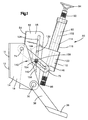
- the present invention includes a mounting bracket 10 (Figs. 1-3) connectable with a vehicle frame, as is known in the art.
- the mounting bracket 10 has a rear wall 12 and a U-shaped portion 14 (Figs. 3) connected with the rear wall.
- the U-shaped portion 14 can be connected with the rear wall 12 by welding.
- the U-shaped portion 14 has a back wall 16 engaging the rear wall 12.
- a pair of side walls 18 and 20 extend from the back wall 16.
- the side walls 18 and 20 extend parallel to each other and generally perpendicular to the back wall 16.
- a pair of foot pedals 26 and 28 (Figs. 1-3) are pivotally connected to the mounting bracket 10 by a pivot shaft 30.
- the foot pedals 26 and 28 are engageable by a foot of an occupant of the vehicle to control vehicle operation.
- the foot pedals 26 and 28 may be used to control braking of the vehicle or operation of a clutch, as is known in the art.
- the side wall 18 (Fig. 3) of the mounting bracket 10 has an opening 34 and the side wall 20 has an opening 36.
- the foot pedal 26 has an arm 38 with an opening 40.
- the foot pedal 28 has an arm 42 with an opening 44.
- the pivot shaft 30 extends through the openings 34 and 36 in the side walls 18 and 20 and through the openings 40 and 44 in the foot pedals 26 and 28 to pivotally connect the foot pedals to the mounting bracket 10.
- the pivot shaft 30 (Figs. 1-3) also pivotally connects a steering column 50 to the mounting bracket 10.
- the pivot shaft 30 extends through a bracket member 52 (Fig. 3) of the steering column 50.
- the bracket member 52 has a back wall 54 and two side walls 56 and 58.
- the side walls 56 and 58 extend generally parallel to each other and perpendicular to the back wall 54.
- the side wall 56 of the bracket member 52 has an opening 62 and the side wall 58 has an opening 64.
- the pivot shaft 30 extends through the openings 62 and 64 to pivotally connect the steering column 50 to the mounting bracket 10.
- a pair of arms 70 and 72 extends from the mounting bracket 10 to the bracket member 52 of the steering column 50.
- the arms 70 and 72 are pivotally connected to the mounting bracket 10 by a pivot shaft 74.
- the side wall 18 (Fig. 3) of the mounting bracket 10 has an opening 78 and the side wall 20 has an opening 80.
- the arm 70 has an opening 82 and the arm 72 has an opening 84.
- the pivot shaft 74 extends through the openings 78 and 80 in the side walls 18 and 20 and through the openings 82 and 84 in the arms 70 and 72 to pivotally connect the arms to the mounting bracket 10.
- the steering column 50 (Figs. 1-2) includes a rotatable steering column member 90.
- the steering column member 90 has an end 92 connectable with a steering wheel 94 in a manner known in the art.
- the universal joint connected with the end 96 of the steering column member 90 is connected with a mechanism (not shown) designed to transmit movement of the steering column member 90 to a steering gear and permit movement of the steering column member relative to the mechanism, as is known in the art.
- a support 100 supports the steering column member 90 for rotation about a longitudinal axis 102 of the steering column member.
- the steering column member 90 rotates about the longitudinal axis 102.
- steerable vehicle wheels (not shown) are turned, as is known in the art.
- the support 100 (Figs. 1 and 2) has a main body 110 through which the steering column member 90 extends.
- the main body 110 is made from casting and may have any desired shape.
- the main body 110 has a cylindrical portion 114.
- a tube 116, through which the steering column member 90 extends, is press fit on the cylindrical portion 114.
- a pair of bearings 120 (Fig. 3) support the steering column member 90 for rotation relative to the support 100.
- the side wall 56 of the bracket member 52 has a slot 126.
- the side wall 58 of the bracket member 52 has a slot 128 extending generally parallel to the slot 126.
- a steering column pivot shaft 130 pivotally connects the support 100 with the bracket member 52.
- the pivot shaft 130 extends through an opening 132 in the main body 110 of the support 100.
- the pivot shaft 130 also extends through the slots 126 and 128 in the side walls 56 and 58.
- the pivot shaft 130 is movable along the slots 126 and 128 relative to the bracket member 52 in a direction extending transverse to a longitudinal extent of the steering column pivot shaft 130 and extending transverse to a longitudinal extent of the pivot shaft 30.
- a locking mechanism 140 locks the steering column 50 in any one of a plurality of pivot positions relative to the mounting bracket 10.
- the locking mechanism 140 locks the support 100 in any one of a plurality of pivot positions relative to the bracket member 52.
- the locking mechanism 140 also locks the steering column pivot shaft 130 in any one of a plurality of positions along the slots 126 and 128 relative to the bracket member 52.
- the locking mechanism 140 (Figs. 1-3) includes a locking shaft or bolt 142 which extends through an arcuate slot 144 in the main body 110 of the support 100.
- the bolt 142 also extends through the slots 126 and 128 in the side walls 56 and 58 of the bracket member 52. Furthermore, the bolt 142 extends through slots 146 and 148 in the arms 70 and 72.
- the locking mechanism 140 includes a nut 154 which is threaded onto the bolt 142.
- a handle 156 extends from the nut 154.
- the handle 156 is movable by an occupant of the vehicle to actuate the locking mechanism 140.
- the bolt 142 (Fig. 3) extends through a pair of washers 158 which engage the arms 70 and 72.
Landscapes
- Engineering & Computer Science (AREA)
- Transportation (AREA)
- Mechanical Engineering (AREA)
- Chemical & Material Sciences (AREA)
- Combustion & Propulsion (AREA)
- Physics & Mathematics (AREA)
- General Physics & Mathematics (AREA)
- Automation & Control Theory (AREA)
- Steering Controls (AREA)
- Body Structure For Vehicles (AREA)
Abstract
Description
Claims (10)
- An apparatus comprising:a mounting bracket connectable with a vehicle frame;a foot pedal which controls a vehicle operation pivotally connected to the mounting bracket by a pivot shaft;a steering column pivotally connected to said mounting bracket by said pivot shaft, said steering column including a steering column member connectable with a steering wheel and rotatable to turn steerable vehicle wheels; anda locking mechanism which locks said steering column in any one of a plurality of pivot positions relative to said mounting bracket.
- An apparatus as defined in claim 1 further including a pair of arms extending between said mounting bracket and said steering column, each of said arms being pivotally connected to said mounting bracket,and/ or wherein preferably said steering column is movable relative to each of said arms,and/ or wherein preferably said locking mechanism includes a locking shaft extending through said steering column and a slot in each of said arms,and/ or wherein preferably said locking mechanism presses said arms toward each other and toward said steering column to lock said steering column in any one of a plurality of pivot positions relative to said mounting bracket.
- An apparatus as defined in claim 1 wherein said steering column includes a bracket member pivotally connected to said mounting bracket by said pivot shaft and a support connected with said bracket member which supports said steering column member for rotation about a longitudinal axis of said steering column member, said support being movable relative to said bracket member in a direction extending transverse to a longitudinal extent of said pivot shaft.
- An apparatus as defined in claim 1 wherein said steering column includes an bracket member pivotally connected to said mounting bracket by said pivot shaft and a support member pivotally connected to said bracket member which supports said steering column member for rotation about a longitudinal axis of said steering column,and/ or wherein preferably said support is pivotally connected to said bracket member by a steering column pivot shaft,and/ or wherein preferably said steering column pivot shaft is movable relative to said bracket member in a direction transverse to a longitudinal extent of said steering column pivot shaft.
- An apparatus as defined in one of the preceding claims, wherei said locking mechanism locks said support in any one of a plurality of pivot positions relative to said bracket member and locks said steering column pivot shaft in any one of a plurality of positions along the direction transverse to the longitudinal extent of said steering column pivot shaft relative to said bracket member.
- An apparatus as defined in one of the preceding claims, further including a pair of arms extending between said mounting bracket and said bracket member, each of said arms being pivotally connected to said mounting bracket, and said bracket member being movable relative to each of said arms.
- An apparatus as defined in one of the preceding claims, wherein said locking mechanism includes a locking shaft extending through said bracket member, said support, and a slot in each of said arms,and/ or wherein preferably said locking mechanism presses said arms toward each other and toward said bracket member to lock said bracket member in any one of a plurality of pivot positions relative to said mounting bracket.
- An apparatus as defined in one of the preceding claims, wherein said support includes an arcuate opening through which said locking shaft extends.
- An apparatus as defined in one of the preceding claims, wherein said bracket member includes first and second side walls extending generally parallel to each other, said first side wall having a first slot and said second side wall having a second slot extending generally parallel to said first slot, said steering column pivot shaft extending through said support and said first and second slots and being movable along said first and second slots relative to said bracket member, said locking shaft extending through said first and second slots.
- An apparatus comprising:a mounting bracket connectable with a vehicle frame;a foot pedal which controls a vehicle operation pivotally connected to the mounting bracket by a pivot shaft; anda steering column pivotally connected to said mounting bracket by said pivot shaft.
Applications Claiming Priority (2)
| Application Number | Priority Date | Filing Date | Title |
|---|---|---|---|
| US09/697,824 US6474189B1 (en) | 2000-10-26 | 2000-10-26 | Apparatus for mounting a foot pedal and a steering column to a vehicle |
| US697824 | 2000-10-26 |
Publications (3)
| Publication Number | Publication Date |
|---|---|
| EP1201526A2 true EP1201526A2 (en) | 2002-05-02 |
| EP1201526A3 EP1201526A3 (en) | 2003-06-18 |
| EP1201526B1 EP1201526B1 (en) | 2005-09-14 |
Family
ID=24802714
Family Applications (1)
| Application Number | Title | Priority Date | Filing Date |
|---|---|---|---|
| EP01125532A Expired - Lifetime EP1201526B1 (en) | 2000-10-26 | 2001-10-25 | An apparatus for mounting a foot pedal and a steering column to a vehicle |
Country Status (3)
| Country | Link |
|---|---|
| US (1) | US6474189B1 (en) |
| EP (1) | EP1201526B1 (en) |
| DE (1) | DE60113362T2 (en) |
Cited By (8)
| Publication number | Priority date | Publication date | Assignee | Title |
|---|---|---|---|---|
| EP1435317A3 (en) * | 2003-01-06 | 2004-11-17 | Mando Corporation | Tilt adjusting for steering columns |
| EP1535823A4 (en) * | 2002-07-25 | 2006-11-15 | Nsk Ltd | Steering column device |
| EP1547902A4 (en) * | 2002-09-04 | 2006-11-29 | Nsk Ltd | Vehicle position adjustment type steering column device |
| US7866698B2 (en) | 2004-12-22 | 2011-01-11 | Fuji Autotech Ab | Steering wheel adjusting mechanism for motor vehicles |
| US20130205933A1 (en) * | 2011-06-15 | 2013-08-15 | Nsk Ltd. | Steering apparatus |
| CN105292234A (en) * | 2015-11-17 | 2016-02-03 | 江苏华骋科技有限公司 | Pedal type inclinable direction column adjusting mechanism |
| CN110481522A (en) * | 2019-08-13 | 2019-11-22 | 奇瑞汽车股份有限公司 | A kind of brake pedal linkage and driving school's vehicle |
| US20230249736A1 (en) * | 2022-02-10 | 2023-08-10 | Honda Motor Co., Ltd. | Methods and systems for protecting a steering column from debris |
Families Citing this family (17)
| Publication number | Priority date | Publication date | Assignee | Title |
|---|---|---|---|---|
| US6666478B2 (en) * | 2002-05-01 | 2003-12-23 | Trw Inc. | Steering column |
| US7469615B2 (en) * | 2004-02-19 | 2008-12-30 | Delphi Technologies, Inc. | Snap on lower bracket and bearing support |
| US7401814B2 (en) * | 2005-02-21 | 2008-07-22 | Mazda Motor Corporation | Steering device support structure |
| JP4271176B2 (en) * | 2005-09-15 | 2009-06-03 | 本田技研工業株式会社 | Vehicle steering device |
| JP4567040B2 (en) * | 2007-09-07 | 2010-10-20 | 本田技研工業株式会社 | Tilt telescopic steering device |
| FR2934539B1 (en) * | 2008-08-04 | 2010-08-13 | Renault Sas | PEDALER'S CAP WITH RIPAGE RING. |
| US20110088501A1 (en) * | 2009-10-20 | 2011-04-21 | Mando Corporation | Steering column for vehicle |
| JP5234300B2 (en) * | 2010-10-18 | 2013-07-10 | アイシン精機株式会社 | Vehicle steering device |
| US8523227B2 (en) * | 2010-12-13 | 2013-09-03 | Caterpillar Inc. | Single point friction lock for tilt and telescope adjustment of steering columns |
| US20130058706A1 (en) * | 2011-09-07 | 2013-03-07 | Kempter Marketing Inc. | Unified universal rack connector |
| KR101424877B1 (en) * | 2012-08-16 | 2014-08-01 | 주식회사 만도 | Steering Column for Vehicle |
| CN104385914B (en) * | 2014-12-17 | 2017-08-25 | 安徽安凯汽车股份有限公司 | The sectional shelf-unit of section mechanism before a kind of clutch control |
| DE102015112086B4 (en) * | 2015-07-24 | 2022-10-20 | Robert Bosch Automotive Steering Gmbh | DEVICE FOR ADJUSTING A STEERING COLUMN OF A MOTOR VEHICLE AND STEERING SYSTEM |
| DE102015214933A1 (en) * | 2015-08-05 | 2017-02-09 | Deere & Company | Clutch pedal of an agricultural tractor |
| CN108974107B (en) * | 2018-07-03 | 2023-09-12 | 诺力智能装备股份有限公司 | Fork truck steering column angle adjustment mechanism |
| DE102019007742A1 (en) * | 2019-11-04 | 2021-05-06 | Willi Elbe Gelenkwellen Gmbh & Co. Kg | Steering column module for a vehicle steering system |
| KR102938441B1 (en) * | 2023-03-31 | 2026-03-13 | 에이치엘만도 주식회사 | Steering apparatus for vehicle |
Family Cites Families (10)
| Publication number | Priority date | Publication date | Assignee | Title |
|---|---|---|---|---|
| US3198030A (en) | 1961-07-20 | 1965-08-03 | Ford Motor Co | Adjustable steering column |
| US3245282A (en) | 1964-04-13 | 1966-04-12 | Gen Motors Corp | Progressively adjustable steering assembly |
| US3548675A (en) * | 1968-12-16 | 1970-12-22 | Ford Motor Co | Adjustable steering mechanism |
| GB1460027A (en) * | 1973-10-08 | 1976-12-31 | Chrysler Uk | Motor vehicles process for producing 3,5-cyclic adenylic acid |
| DE2430546A1 (en) * | 1974-06-26 | 1976-01-15 | Kloeckner Humboldt Deutz Ag | Steering column for agricultural vehicles - is pivoted coaxial to foot control pedal shaft to maintain relationship |
| ES494694A0 (en) | 1980-07-30 | 1981-04-01 | Bendiberica Sa | IMPROVEMENTS IN MECHANISMS FOR ADJUSTING THE POSITION OF THE STEERING WHEEL IN VEHICLES |
| SE8803943D0 (en) | 1988-10-31 | 1988-10-31 | Ffv Autotech Ab | STEERING MOUNTING PARTS WITH SLIDING AND TIP FUNCTION |
| SE465563B (en) | 1989-10-31 | 1991-09-30 | Volvo Ab | ADJUSTABLE VEHICLE |
| US5613404A (en) * | 1994-03-07 | 1997-03-25 | Case Corporation | Tiltable steering mechanism for an off-highway implement |
| DE19642956C2 (en) * | 1996-10-17 | 2000-11-23 | Arge Sjs S R L Soc | Control device for steerable vehicles |
-
2000
- 2000-10-26 US US09/697,824 patent/US6474189B1/en not_active Expired - Lifetime
-
2001
- 2001-10-25 EP EP01125532A patent/EP1201526B1/en not_active Expired - Lifetime
- 2001-10-25 DE DE60113362T patent/DE60113362T2/en not_active Expired - Lifetime
Cited By (11)
| Publication number | Priority date | Publication date | Assignee | Title |
|---|---|---|---|---|
| EP1535823A4 (en) * | 2002-07-25 | 2006-11-15 | Nsk Ltd | Steering column device |
| US7350813B2 (en) | 2002-07-25 | 2008-04-01 | Nsk Ltd. | Steering column device |
| EP1547902A4 (en) * | 2002-09-04 | 2006-11-29 | Nsk Ltd | Vehicle position adjustment type steering column device |
| EP1435317A3 (en) * | 2003-01-06 | 2004-11-17 | Mando Corporation | Tilt adjusting for steering columns |
| US7866698B2 (en) | 2004-12-22 | 2011-01-11 | Fuji Autotech Ab | Steering wheel adjusting mechanism for motor vehicles |
| US20130205933A1 (en) * | 2011-06-15 | 2013-08-15 | Nsk Ltd. | Steering apparatus |
| US9039042B2 (en) * | 2011-06-15 | 2015-05-26 | Nsk Ltd. | Steering apparatus |
| CN105292234A (en) * | 2015-11-17 | 2016-02-03 | 江苏华骋科技有限公司 | Pedal type inclinable direction column adjusting mechanism |
| CN110481522A (en) * | 2019-08-13 | 2019-11-22 | 奇瑞汽车股份有限公司 | A kind of brake pedal linkage and driving school's vehicle |
| US20230249736A1 (en) * | 2022-02-10 | 2023-08-10 | Honda Motor Co., Ltd. | Methods and systems for protecting a steering column from debris |
| US11840274B2 (en) * | 2022-02-10 | 2023-12-12 | Honda Motor Co., Ltd. | Methods and systems for protecting a steering column from debris |
Also Published As
| Publication number | Publication date |
|---|---|
| DE60113362T2 (en) | 2006-07-06 |
| DE60113362D1 (en) | 2005-10-20 |
| EP1201526B1 (en) | 2005-09-14 |
| EP1201526A3 (en) | 2003-06-18 |
| US6474189B1 (en) | 2002-11-05 |
Similar Documents
| Publication | Publication Date | Title |
|---|---|---|
| US6474189B1 (en) | Apparatus for mounting a foot pedal and a steering column to a vehicle | |
| US8016310B2 (en) | Wheelchair retrofit assembly with multiple dimensions of adjustment | |
| US5259264A (en) | Adjustable steering wheel | |
| US6829962B2 (en) | Steering column | |
| US20050275205A1 (en) | Small diameter steering wheel apparatus | |
| US5813289A (en) | Steering column | |
| US6357318B1 (en) | Steering column | |
| US6131481A (en) | Steering column | |
| US6357317B1 (en) | Steering column | |
| US6662674B2 (en) | Steering column | |
| US6279951B1 (en) | Steering column | |
| WO1982000806A1 (en) | Tilt steering wheel and support column apparatus | |
| US6240802B1 (en) | Device for adjusting a two-part gear lever | |
| JP2004353569A (en) | Driver assistance device | |
| US6766712B2 (en) | Steering column | |
| JPS635051Y2 (en) | ||
| KR200312912Y1 (en) | A dirving simulation machiene for a mentally handicapped person | |
| JPH0217974Y2 (en) | ||
| US5540308A (en) | Parking lock for vehicle | |
| JPH0224369Y2 (en) | ||
| JPH0247114Y2 (en) | ||
| JPS6344295Y2 (en) | ||
| JP5163925B2 (en) | Car driving assistance pedal | |
| JPS5943168Y2 (en) | tilt steering column | |
| JPH0331663Y2 (en) |
Legal Events
| Date | Code | Title | Description |
|---|---|---|---|
| PUAI | Public reference made under article 153(3) epc to a published international application that has entered the european phase |
Free format text: ORIGINAL CODE: 0009012 |
|
| AK | Designated contracting states |
Kind code of ref document: A2 Designated state(s): AT BE CH CY DE DK ES FI FR GB GR IE IT LI LU MC NL PT SE TR |
|
| AX | Request for extension of the european patent |
Free format text: AL;LT;LV;MK;RO;SI |
|
| PUAL | Search report despatched |
Free format text: ORIGINAL CODE: 0009013 |
|
| AK | Designated contracting states |
Designated state(s): AT BE CH CY DE DK ES FI FR GB GR IE IT LI LU MC NL PT SE TR |
|
| AX | Request for extension of the european patent |
Extension state: AL LT LV MK RO SI |
|
| RIC1 | Information provided on ipc code assigned before grant |
Ipc: 7B 62D 1/18 A Ipc: 7B 60K 23/02 B |
|
| 17P | Request for examination filed |
Effective date: 20031217 |
|
| RAP1 | Party data changed (applicant data changed or rights of an application transferred) |
Owner name: TRW AUTOMOTIVE U.S. LLC |
|
| AKX | Designation fees paid |
Designated state(s): DE ES FR GB IT |
|
| 17Q | First examination report despatched |
Effective date: 20040524 |
|
| GRAP | Despatch of communication of intention to grant a patent |
Free format text: ORIGINAL CODE: EPIDOSNIGR1 |
|
| GRAS | Grant fee paid |
Free format text: ORIGINAL CODE: EPIDOSNIGR3 |
|
| GRAA | (expected) grant |
Free format text: ORIGINAL CODE: 0009210 |
|
| AK | Designated contracting states |
Kind code of ref document: B1 Designated state(s): DE ES FR GB IT |
|
| PG25 | Lapsed in a contracting state [announced via postgrant information from national office to epo] |
Ref country code: IT Free format text: LAPSE BECAUSE OF FAILURE TO SUBMIT A TRANSLATION OF THE DESCRIPTION OR TO PAY THE FEE WITHIN THE PRESCRIBED TIME-LIMIT;WARNING: LAPSES OF ITALIAN PATENTS WITH EFFECTIVE DATE BEFORE 2007 MAY HAVE OCCURRED AT ANY TIME BEFORE 2007. THE CORRECT EFFECTIVE DATE MAY BE DIFFERENT FROM THE ONE RECORDED. Effective date: 20050914 |
|
| REG | Reference to a national code |
Ref country code: GB Ref legal event code: FG4D |
|
| PGFP | Annual fee paid to national office [announced via postgrant information from national office to epo] |
Ref country code: FR Payment date: 20051020 Year of fee payment: 5 |
|
| REF | Corresponds to: |
Ref document number: 60113362 Country of ref document: DE Date of ref document: 20051020 Kind code of ref document: P |
|
| PGFP | Annual fee paid to national office [announced via postgrant information from national office to epo] |
Ref country code: ES Payment date: 20051028 Year of fee payment: 5 |
|
| PG25 | Lapsed in a contracting state [announced via postgrant information from national office to epo] |
Ref country code: ES Free format text: LAPSE BECAUSE OF FAILURE TO SUBMIT A TRANSLATION OF THE DESCRIPTION OR TO PAY THE FEE WITHIN THE PRESCRIBED TIME-LIMIT Effective date: 20051225 |
|
| PLBE | No opposition filed within time limit |
Free format text: ORIGINAL CODE: 0009261 |
|
| STAA | Information on the status of an ep patent application or granted ep patent |
Free format text: STATUS: NO OPPOSITION FILED WITHIN TIME LIMIT |
|
| 26N | No opposition filed |
Effective date: 20060615 |
|
| PG25 | Lapsed in a contracting state [announced via postgrant information from national office to epo] |
Ref country code: FR Free format text: LAPSE BECAUSE OF FAILURE TO SUBMIT A TRANSLATION OF THE DESCRIPTION OR TO PAY THE FEE WITHIN THE PRESCRIBED TIME-LIMIT Effective date: 20061020 |
|
| EN | Fr: translation not filed | ||
| EN | Fr: translation not filed | ||
| GBPC | Gb: european patent ceased through non-payment of renewal fee |
Effective date: 20061025 |
|
| PG25 | Lapsed in a contracting state [announced via postgrant information from national office to epo] |
Ref country code: GB Free format text: LAPSE BECAUSE OF NON-PAYMENT OF DUE FEES Effective date: 20061025 |
|
| PGFP | Annual fee paid to national office [announced via postgrant information from national office to epo] |
Ref country code: GB Payment date: 20051104 Year of fee payment: 5 |
|
| PGFP | Annual fee paid to national office [announced via postgrant information from national office to epo] |
Ref country code: DE Payment date: 20191015 Year of fee payment: 19 |
|
| REG | Reference to a national code |
Ref country code: DE Ref legal event code: R119 Ref document number: 60113362 Country of ref document: DE |
|
| PG25 | Lapsed in a contracting state [announced via postgrant information from national office to epo] |
Ref country code: DE Free format text: LAPSE BECAUSE OF NON-PAYMENT OF DUE FEES Effective date: 20210501 |