EP1201493A2 - Vehicle-seat covering system - Google Patents
Vehicle-seat covering system Download PDFInfo
- Publication number
- EP1201493A2 EP1201493A2 EP01125909A EP01125909A EP1201493A2 EP 1201493 A2 EP1201493 A2 EP 1201493A2 EP 01125909 A EP01125909 A EP 01125909A EP 01125909 A EP01125909 A EP 01125909A EP 1201493 A2 EP1201493 A2 EP 1201493A2
- Authority
- EP
- European Patent Office
- Prior art keywords
- seat
- puller
- cover
- cover assembly
- vehicle
- Prior art date
- Legal status (The legal status is an assumption and is not a legal conclusion. Google has not performed a legal analysis and makes no representation as to the accuracy of the status listed.)
- Granted
Links
- 239000000463 material Substances 0.000 claims abstract description 12
- 238000009958 sewing Methods 0.000 claims abstract description 5
- 229920001971 elastomer Polymers 0.000 description 9
- 239000005060 rubber Substances 0.000 description 9
- 238000000034 method Methods 0.000 description 5
- 238000007796 conventional method Methods 0.000 description 2
- 239000004744 fabric Substances 0.000 description 2
- 230000000694 effects Effects 0.000 description 1
Images



Classifications
-
- B—PERFORMING OPERATIONS; TRANSPORTING
- B60—VEHICLES IN GENERAL
- B60N—SEATS SPECIALLY ADAPTED FOR VEHICLES; VEHICLE PASSENGER ACCOMMODATION NOT OTHERWISE PROVIDED FOR
- B60N2/00—Seats specially adapted for vehicles; Arrangement or mounting of seats in vehicles
- B60N2/58—Seat coverings
- B60N2/5816—Seat coverings attachments thereof
- B60N2/5825—Seat coverings attachments thereof by hooks, staples, clips, snap fasteners or the like
-
- B—PERFORMING OPERATIONS; TRANSPORTING
- B60—VEHICLES IN GENERAL
- B60N—SEATS SPECIALLY ADAPTED FOR VEHICLES; VEHICLE PASSENGER ACCOMMODATION NOT OTHERWISE PROVIDED FOR
- B60N2/00—Seats specially adapted for vehicles; Arrangement or mounting of seats in vehicles
- B60N2/58—Seat coverings
- B60N2/5816—Seat coverings attachments thereof
- B60N2/5883—Seat coverings attachments thereof by sewing, stitching or threading
Definitions
- This invention relates to a system for covering the seat of a motor vehicle.
- a material-pulling wire such as an end wire 5 as shown in Fig. 5 and Fig.7 is mainly used, and a seat 3 is constituted in such a way that a seat-cover assembly unit 1 covers a seat-pad assembly 2.
- an end wire 5 that passes through the inside of a pulling-material bag 4 of the seat-cover assembly 1 and an insert wire 6 of the seat-pad assembly 2 are affixed with a C-ring 7 as shown in Fig. 7(b).
- a fixing method using a pulling rubber as shown in Fig. 8 ⁇ Fig.10 also can be used instead of the above-mentioned method.
- the fixing method using a pulling rubber requires complicated processing operations similar to those using said material-pulling wire.
- a pulling rubber 8 is hooked over the end wire 5 (see Fig. 5) of the seat-cover assembly 1 and the bottom part of the pulling rubber 8 is hooked over a rear wire 10 of the seat-cover assembly 1 (F is the front face and R is the rear face).
- the object of this invention is to provide (1) a system for installing the seat cover on the seat of a vehicle in such a way that the covered seat has a good appearance and (2) a simple mechanism whereby the seat-cover assembly of the side section of the front side of the seat snugly fits the shape of the seat-pad assembly.
- this invention is characterized such that a material-puller is arranged, along the boundary between the side section and the main central section of the seat-cover assembly that covers the seat, in such a way that (a) said material-puller's top-end side of an appropriate length is affixed to the boundary between the rear-bottom part of said main central section and the rear-bottom part of the side section, (b) said material-puller's bottom end is affixed to the front of a trail gore at the back-face bottom end of said central-front section of the seat-cover assembly in the last step of sewing the cover on the seat, and (c) said seat-cover assembly is attached to the seat by pulling the bottom end of said seat-cover assembly in the backside direction.
- Said material-puller is characterized such that it is composed of a material having less stretching capability than that of said seat-cover.
- Fig. 1 ⁇ Fig.4 show a vehicle seat 3 in one embodiment of this invention. Because the central section 1a of the front of the vehicle seat 3 is covered by use of a method that includes use of a material-puller similar to that of the prior art (see Fig. 5 ⁇ Fig.7), a detailed description of the central section 1a of the front of the vehicle seat 3 will be omitted.
- the top end of the material-puller 11 of an appropriate size is affixed to the boundary between the rear-bottom part of the central section and the rear-bottom part of the side section, and the bottom end of the material-puller 11 is affixed to the rear-bottom part of the central section 1a, as shown in Fig. 1 (U indicates up, and D indicates down) and Fig. 2.
- the material-puller 11 is designed for pulling said side section 1b to the central section 1a.
- a boundary fixing part 20a (of an appropriate length) of the material-puller 11 at a side-top end 11a of is sewn and affixed to the boundary 20 at the rear-bottom part of said central section 1a together with the side section 1b, and also a bottom-end fixing part 21a of the material-puller 11 is sewn to the front of a trail gore 21 at the back-face bottom end of said central section 1a in the last step of sewing the cover on the seat.
- said material-pullers 11 are sewn on said seat-cover assembly 1 in such a way that said material-pullers 11 have tension, and the front of a trail gore 21 at the bottom end of said seat-cover assembly 1 is pulled in the rear direction R as shown in Fig. 4(b).
- said material-puller 11 be composed of a material such as cloth of less stretching capability than that of the seat-cover assembly 1.
- the seat-cover assembly 1 is pulled downwards as described above. Since said material-puller 11 is shorter than said seat-cover assembly 1 as shown in Fig. 4(b) (F means a front face and R means a rear face), it snugly fits the seat-pad assembly 2 so as to remove clearances X and Y between the seat-cover assembly 1 and the seat-pad assembly 2, so as to prevent the seat-cover assembly 1 from fitting the seat-pad assembly 2 too loosely.
Landscapes
- Engineering & Computer Science (AREA)
- Aviation & Aerospace Engineering (AREA)
- Transportation (AREA)
- Mechanical Engineering (AREA)
- Textile Engineering (AREA)
- Seats For Vehicles (AREA)
Abstract
Description
- This invention relates to a system for covering the seat of a motor vehicle.
- In a conventional method of installing a seat cover on the seat of a vehicle, a material-pulling wire, such as an
end wire 5 as shown in Fig. 5 and Fig.7 is mainly used, and aseat 3 is constituted in such a way that a seat-cover assembly unit 1 covers a seat-pad assembly 2. - As to a seat with a high round part as shown on the line B―B in Fig. 7, if the
boundary 20 between aside section 1b and thecentral section 1a of the front side of a seat-cover assembly 1 is not affixed, the seat-cover assembly 1 at said boundary 20 (of a concave shape) will not snugly fit the seat-pad assembly 2, which results in the cover having a bad appearance. As a result, complicated processing operations as described below must be performed. - Similarly, as to a
center section 3a andside sections 3b of a the front side of aseat 3, anend wire 5 that passes through the inside of a pulling-material bag 4 of the seat-cover assembly 1 and aninsert wire 6 of the seat-pad assembly 2 are affixed with a C-ring 7 as shown in Fig. 7(b). - For
side sections 3b of the front side of aseat 3, a fixing method using a pulling rubber as shown in Fig. 8―Fig.10 also can be used instead of the above-mentioned method. However, the fixing method using a pulling rubber requires complicated processing operations similar to those using said material-pulling wire. - That is, as shown in Fig. 10(c) and Fig. 10(d), the top part of a pulling
rubber 8 is hooked over the end wire 5 (see Fig. 5) of the seat-cover assembly 1 and the bottom part of thepulling rubber 8 is hooked over arear wire 10 of the seat-cover assembly 1 (F is the front face and R is the rear face). - However, such prior art as that described above has the problem that the complicated processing operations mentioned above are required in order to prevent the seat-cover assembly at the boundary (of a concave shape), between the main part and the side section of the seat from fitting the seat-pad assembly too loosely.
- For the purpose of solving the above-mentioned problem, the object of this invention is to provide (1) a system for installing the seat cover on the seat of a vehicle in such a way that the covered seat has a good appearance and (2) a simple mechanism whereby the seat-cover assembly of the side section of the front side of the seat snugly fits the shape of the seat-pad assembly.
- For the purpose of solving the aforementioned problem, this invention is characterized such that a material-puller is arranged, along the boundary between the side section and the main central section of the seat-cover assembly that covers the seat, in such a way that (a) said material-puller's top-end side of an appropriate length is affixed to the boundary between the rear-bottom part of said main central section and the rear-bottom part of the side section, (b) said material-puller's bottom end is affixed to the front of a trail gore at the back-face bottom end of said central-front section of the seat-cover assembly in the last step of sewing the cover on the seat, and (c) said seat-cover assembly is attached to the seat by pulling the bottom end of said seat-cover assembly in the backside direction.
- Said material-puller is characterized such that it is composed of a material having less stretching capability than that of said seat-cover.
-
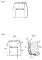
- Fig. 1 shows a method of covering a vehicle seat using a material-puller in one embodiment of this invention; (a) is a partial plan view, and (b) is a sectional view along the line H―H.
- Fig. 2 shows a view of the outside of a seat-cover assembly for a vehicle seat for vehicle using a material-puller in one embodiment of this invention.
- Fig. 3 is a view of the outside of a seat-pad assembly for a vehicle seat using a material-puller in one embodiment of this invention.
- Fig. 4(a) is a view of the outside of a vehicle seat using a material-puller in one embodiment of this invention, and Fig. 4(b) is a partial sectional view along the line A―A.
- Fig. 5 is a view of the outside of a seat-cover assembly of a vehicle seat using a conventional material-pulling wire.
- Fig. 6 is a view of the outside of a seat-pad assembly of a vehicle seat using a conventional material-pulling wire.
- Fig. 7(a) is a view of the outside of a vehicle seat using a conventional material-pulling wire, and Fig. 7(b) is a partial sectional view along the line B―B.
- Fig. 8(a) is a view of the outside of a seat-cover assembly of a vehicle seat using a conventional material-pulling rubber, and Fig. 8(b) is a partial rear-face view (the bottom part) of Fig. 8(a).
- Fig. 9 is a view of the outside of a seat-pad assembly of a vehicle seat using a conventional material-pulling rubber.
- Fig. 10(a) is a view of the outside of a vehicle seat using a conventional material-pulling rubber; Fig. 10(b) is a partial rear-face view (the bottom part) of Fig. 10(a); Fig. 10(c) is a partial sectional view along the line C―C; and Fig. 10(d) is a partial appearance view seen from side R of Fig. 10(c).
-
- The present invention will now be described in detail with reference to the accompanying drawings.
- Fig. 1―Fig.4 show a
vehicle seat 3 in one embodiment of this invention. Because thecentral section 1a of the front of thevehicle seat 3 is covered by use of a method that includes use of a material-puller similar to that of the prior art (see Fig. 5―Fig.7), a detailed description of thecentral section 1a of the front of thevehicle seat 3 will be omitted. - The
side section 1b (or 3b) of the front of aseat 3 will now be described in detail. - At the
boundary 20 between theside section 1b and thecentral section 1a of the seat-cover assembly 1, when thecentral section 1a and theside section 1b (comer part) are sewn together, the top end of the material-puller 11 of an appropriate size is affixed to the boundary between the rear-bottom part of the central section and the rear-bottom part of the side section, and the bottom end of the material-puller 11 is affixed to the rear-bottom part of thecentral section 1a, as shown in Fig. 1 (U indicates up, and D indicates down) and Fig. 2. - The material-
puller 11 is designed for pulling saidside section 1b to thecentral section 1a. - A
boundary fixing part 20a (of an appropriate length) of the material-puller 11 at a side-top end 11a of is sewn and affixed to theboundary 20 at the rear-bottom part of saidcentral section 1a together with theside section 1b, and also a bottom-end fixing part 21a of the material-puller 11 is sewn to the front of atrail gore 21 at the back-face bottom end of saidcentral section 1a in the last step of sewing the cover on the seat. - At this time, said material-
pullers 11 are sewn on said seat-cover assembly 1 in such a way that said material-pullers 11 have tension, and the front of a trail gore 21 at the bottom end of said seat-cover assembly 1 is pulled in the rear direction R as shown in Fig. 4(b). - It is preferable that said material-
puller 11 be composed of a material such as cloth of less stretching capability than that of the seat-cover assembly 1. At the time of covering, the seat-cover assembly 1 is pulled downwards as described above. Since said material-puller 11 is shorter than said seat-cover assembly 1 as shown in Fig. 4(b) (F means a front face and R means a rear face), it snugly fits the seat-pad assembly 2 so as to remove clearances X and Y between the seat-cover assembly 1 and the seat-pad assembly 2, so as to prevent the seat-cover assembly 1 from fitting the seat-pad assembly 2 too loosely. - This invention, as described in detail above, has the following desirable effects that the prior art does not have:
- (1) A material-puller (composed of a material such as cloth with less stretching capability than that of the seat-cover) is arranged in such a way that the material-puller's top-end side section of an appropriate length is affixed to the boundary between the back-face bottom part of the central section and the bottom part of the side section of the seat-cover, and that the material-puller's bottom end is affixed to the front of a trail gore at the back-face bottom end of the central section in the last step of sewing the cover on the seat. Then, because the bottom end of said seat-cover is pulled in the rear direction so that said seat-cover assembly is snugly attached to the seat pad, the seat-cover assembly does not fit the seat-pad assembly too loosely even in the case of a seat with an especially high round part, resulting in an improvement in the appearance of the seat cover.
- (2) When the side section of the front of the seat is covered according to the
system of this invention, the number of parts needed can be less than with the
conventional method, so as to reduce costs and improve working efficiency. For
example, if this invention's system is applied, two material-pulling rubbers, two
pulling-material bags, one rear pulling-material bag (a rear pulling-material bag
is represented by the
number 9 in Fig. 10), and one rear wire can be omitted (although two material-pullers need to be added). -
-
- 1
- Seat-cover assembly
- 1a
- Main part of seat-cover assembly
- 1b
- Side part of seat-cover assembly
- 2
- Seat-pad assembly
- 3
- Seat
- 3a
- Main part of seat
- 3b
- Side part of seat
- 4
- Pulling-material bag
- 5
- End wire
- 6
- Insert wire
- 7
- C-ring
- 8
- Hoisting rubber
- 9
- Rear pulling-material bag
- 10
- Rear wire
- 11
- Material-puller
- 11a
- Top end of material-puller
- 20
- Boundary between side section and central section of front side of seat-cover assembly
- 20a
- Boundary fixing part
- 21
- Front of trail gore
- 21a
- Bottom-end fixing part
- D
- Down
- F
- Front
- R
- Rear
- U
- Up
- X, Y
- Clearances
Claims (2)
- A system for installing a seat cover on a the seat of a vehicle, whereby a material-puller is arranged such that said material-puller's top-end side section of an appropriate length is affixed to a boundary between the back-face bottom part of the central section and the back-face bottom part of a side section of the front of a seat-cover assembly that is used to cover the seat, and such that said material-puller's bottom end is affixed to the front of a trail gore at the back-face bottom end of said central section in the last step of sewing the cover on the seat, and wherein the bottom end of said seat-cover assembly is pulled in the backside direction in order to attach said seat-cover assembly to the seat.
- A system for installing a seat cover on the seat of a vehicle, as described in Claim 1, whereby said material-puller is composed of a material having less stretching capability than that of said seat-cover.
Applications Claiming Priority (2)
| Application Number | Priority Date | Filing Date | Title |
|---|---|---|---|
| JP2000333744A JP3689887B2 (en) | 2000-10-31 | 2000-10-31 | Vehicle seat |
| JP2000333744 | 2000-10-31 |
Publications (3)
| Publication Number | Publication Date |
|---|---|
| EP1201493A2 true EP1201493A2 (en) | 2002-05-02 |
| EP1201493A3 EP1201493A3 (en) | 2003-12-17 |
| EP1201493B1 EP1201493B1 (en) | 2006-08-09 |
Family
ID=18809774
Family Applications (1)
| Application Number | Title | Priority Date | Filing Date |
|---|---|---|---|
| EP01125909A Expired - Lifetime EP1201493B1 (en) | 2000-10-31 | 2001-10-30 | Vehicle-seat covering system |
Country Status (4)
| Country | Link |
|---|---|
| US (1) | US7588290B2 (en) |
| EP (1) | EP1201493B1 (en) |
| JP (1) | JP3689887B2 (en) |
| DE (1) | DE60122086T2 (en) |
Families Citing this family (14)
| Publication number | Priority date | Publication date | Assignee | Title |
|---|---|---|---|---|
| JP5098612B2 (en) * | 2007-12-07 | 2012-12-12 | トヨタ紡織株式会社 | Piece for skin material of vehicle seat and manufacturing method thereof |
| DE102009039153A1 (en) * | 2009-08-27 | 2011-03-17 | Lear Corp., Southfield | Seat arrangement with a reference |
| DE102010039006A1 (en) * | 2010-08-06 | 2012-02-09 | Bayerische Motoren Werke Aktiengesellschaft | Joint assembly for dunnage rod in vehicle seat, has multiple connection regions, where multiple dunnage rods are connected together by connecting elements |
| US8820833B2 (en) * | 2011-11-09 | 2014-09-02 | Tachi-S Co., Ltd. | Structure of trim cover assembly for seat back |
| JP6634306B2 (en) * | 2016-02-09 | 2020-01-22 | 株式会社タチエス | Seat covers and vehicle seats |
| DE102016205472A1 (en) * | 2016-04-01 | 2017-10-05 | Ford Global Technologies, Llc | Upholstery element for a vehicle seat |
| US10473136B2 (en) * | 2017-05-25 | 2019-11-12 | Ford Global Technologies, Llc | Vehicle seating cushion with snap-fit fasteners to interconnect with snap-fit receivers on a structural support |
| JP6900807B2 (en) * | 2017-07-05 | 2021-07-07 | トヨタ紡織株式会社 | Interior goods |
| JP7412875B2 (en) * | 2018-04-09 | 2024-01-15 | 株式会社タチエス | vehicle seat |
| US10532675B2 (en) * | 2018-05-31 | 2020-01-14 | GM Global Technology Operations LLC | Vehicle seat trim cover with integrally knitted attachment features |
| US10808336B2 (en) | 2018-05-31 | 2020-10-20 | GM Global Technology Operations LLC | Vehicle seat trim covers with knitted attachment structures formed with heat-activated yarns |
| US10843600B2 (en) | 2018-07-12 | 2020-11-24 | GM Global Technology Operations LLC | Vehicle seat trim covers including integrally-knit backing materials and methods of manufacturing vehicle seat trim covers |
| DE102020104233A1 (en) * | 2019-08-05 | 2021-02-11 | Adient Engineering and IP GmbH | Seat cushion element and vehicle seat |
| US11433791B2 (en) * | 2020-04-09 | 2022-09-06 | Lear Corporation | Trim assembly for a vehicle seat and method of forming |
Family Cites Families (14)
| Publication number | Priority date | Publication date | Assignee | Title |
|---|---|---|---|---|
| US2156629A (en) * | 1937-12-11 | 1939-05-02 | Hutchison Miller Reese | Seat |
| DE1909235A1 (en) | 1969-02-25 | 1970-09-10 | Opel Adam Ag | Car seat pad spring and cover clip |
| US4317591A (en) * | 1980-05-27 | 1982-03-02 | General Motors Corporation | Vehicle seat bolster wire assembly |
| FR2618996B1 (en) * | 1987-08-05 | 1989-12-22 | Peugeot Cycles | SEAT ELEMENT, ESPECIALLY FOR A MOTOR VEHICLE |
| US4772070A (en) * | 1987-12-03 | 1988-09-20 | Leto Jr James | Contoured seat covering for automotive vehicle bench seat |
| FR2636320B1 (en) | 1988-09-14 | 1993-12-10 | Nobel Plastiques | HANGING DEVICE FOR REALIZING SEAT COVERING TISSUE RECALLS |
| FR2655595B1 (en) | 1989-12-11 | 1992-03-13 | Peugeot | DEVICE FOR RECALLING THE HEADPHONES OF A MOTOR VEHICLE SEAT. |
| US5216772A (en) * | 1992-08-25 | 1993-06-08 | Clute L Jason | Support pillow |
| US5338098A (en) * | 1993-04-23 | 1994-08-16 | Tachi-S Co., Ltd. | Seat back of an automotive seat |
| ES2072224B1 (en) * | 1993-11-25 | 1997-09-01 | Alvarez Argimiro Lopez | FIRE-OFF MACHINE FOR FORESTS. |
| FR2730198B1 (en) * | 1995-02-08 | 1997-04-11 | Faure Bertrand Equipements Sa | HEADDRESS FOR VEHICLE SEAT BACKREST AND SEAT INCLUDING SUCH A HEADDRESS |
| JP3335849B2 (en) * | 1996-09-03 | 2002-10-21 | トヨタ自動車株式会社 | Seat structure with side airbag device |
| JP3380150B2 (en) * | 1997-12-12 | 2003-02-24 | ジョンソン コントロールズ オートモーティブ システムズ株式会社 | Seat skin support structure |
| US6345866B1 (en) * | 2000-08-03 | 2002-02-12 | Usa Products | Adjustable seat covers for high or low back seats |
-
2000
- 2000-10-31 JP JP2000333744A patent/JP3689887B2/en not_active Expired - Fee Related
-
2001
- 2001-10-24 US US09/983,494 patent/US7588290B2/en not_active Expired - Fee Related
- 2001-10-30 DE DE60122086T patent/DE60122086T2/en not_active Expired - Lifetime
- 2001-10-30 EP EP01125909A patent/EP1201493B1/en not_active Expired - Lifetime
Non-Patent Citations (1)
| Title |
|---|
| None |
Also Published As
| Publication number | Publication date |
|---|---|
| EP1201493A3 (en) | 2003-12-17 |
| DE60122086D1 (en) | 2006-09-21 |
| EP1201493B1 (en) | 2006-08-09 |
| US20020050734A1 (en) | 2002-05-02 |
| US7588290B2 (en) | 2009-09-15 |
| DE60122086T2 (en) | 2006-11-30 |
| JP2002136398A (en) | 2002-05-14 |
| JP3689887B2 (en) | 2005-08-31 |
Similar Documents
| Publication | Publication Date | Title |
|---|---|---|
| EP1201493B1 (en) | Vehicle-seat covering system | |
| US6588838B1 (en) | Reinforced seat cover | |
| US6345866B1 (en) | Adjustable seat covers for high or low back seats | |
| CN1767968B (en) | Child seat cover | |
| US5938232A (en) | Force directing air bag deployment pocket | |
| US6578923B2 (en) | Seat back for a vehicle | |
| EP0788941A3 (en) | Seat structure having a side impact air bag apparatus | |
| USRE38272E1 (en) | Golf cart frame enclosure attachment device | |
| EP0818364A3 (en) | Airbag module with deployment chute | |
| EP0334508B1 (en) | Vehicle seat trim assembly | |
| EP1179308A4 (en) | Seat back frame assembly of vehicle seat | |
| US5979979A (en) | Vehicle seat fitted with a side-positioned safety airbag | |
| CA1320597C (en) | Closure for seat back cover | |
| JP2010228614A (en) | Operation strap of vehicle seat | |
| JPH0742358Y2 (en) | Car seat cover | |
| JP2016210415A (en) | Airbag module equipped seat and mounting member | |
| JPH06277375A (en) | Seat back trim cover terminal processing structure | |
| JP4175253B2 (en) | Vehicle seat | |
| JP3731075B2 (en) | Airbag module built-in seat | |
| JPH1133247A (en) | Trim cover suspension structure for seat back | |
| JP2860762B2 (en) | Vehicle seat | |
| KR200239311Y1 (en) | A securing device of regulating position for automobile seat-belt | |
| KR200219634Y1 (en) | Back cover structure of backrest | |
| JP3731074B2 (en) | Airbag module built-in seat | |
| JPH0576667A (en) | Suspension and fastening method for seat skin material in vehicle seat |
Legal Events
| Date | Code | Title | Description |
|---|---|---|---|
| PUAI | Public reference made under article 153(3) epc to a published international application that has entered the european phase |
Free format text: ORIGINAL CODE: 0009012 |
|
| AK | Designated contracting states |
Kind code of ref document: A2 Designated state(s): AT BE CH CY DE DK ES FI FR GB GR IE IT LI LU MC NL PT SE TR |
|
| AX | Request for extension of the european patent |
Free format text: AL;LT;LV;MK;RO;SI |
|
| PUAL | Search report despatched |
Free format text: ORIGINAL CODE: 0009013 |
|
| AK | Designated contracting states |
Kind code of ref document: A3 Designated state(s): AT BE CH CY DE DK ES FI FR GB GR IE IT LI LU MC NL PT SE TR |
|
| AX | Request for extension of the european patent |
Extension state: AL LT LV MK RO SI |
|
| RIC1 | Information provided on ipc code assigned before grant |
Ipc: 7A 47C 31/02 B Ipc: 7B 60N 2/58 A |
|
| 17P | Request for examination filed |
Effective date: 20031219 |
|
| AKX | Designation fees paid |
Designated state(s): DE FR |
|
| GRAP | Despatch of communication of intention to grant a patent |
Free format text: ORIGINAL CODE: EPIDOSNIGR1 |
|
| GRAS | Grant fee paid |
Free format text: ORIGINAL CODE: EPIDOSNIGR3 |
|
| GRAA | (expected) grant |
Free format text: ORIGINAL CODE: 0009210 |
|
| AK | Designated contracting states |
Kind code of ref document: B1 Designated state(s): DE FR |
|
| REF | Corresponds to: |
Ref document number: 60122086 Country of ref document: DE Date of ref document: 20060921 Kind code of ref document: P |
|
| ET | Fr: translation filed | ||
| PLBE | No opposition filed within time limit |
Free format text: ORIGINAL CODE: 0009261 |
|
| STAA | Information on the status of an ep patent application or granted ep patent |
Free format text: STATUS: NO OPPOSITION FILED WITHIN TIME LIMIT |
|
| 26N | No opposition filed |
Effective date: 20070510 |
|
| PGFP | Annual fee paid to national office [announced via postgrant information from national office to epo] |
Ref country code: FR Payment date: 20131009 Year of fee payment: 13 Ref country code: DE Payment date: 20131023 Year of fee payment: 13 |
|
| REG | Reference to a national code |
Ref country code: DE Ref legal event code: R119 Ref document number: 60122086 Country of ref document: DE |
|
| PG25 | Lapsed in a contracting state [announced via postgrant information from national office to epo] |
Ref country code: DE Free format text: LAPSE BECAUSE OF NON-PAYMENT OF DUE FEES Effective date: 20150501 |
|
| REG | Reference to a national code |
Ref country code: FR Ref legal event code: ST Effective date: 20150630 |
|
| PG25 | Lapsed in a contracting state [announced via postgrant information from national office to epo] |
Ref country code: FR Free format text: LAPSE BECAUSE OF NON-PAYMENT OF DUE FEES Effective date: 20141031 |