EP1201461A1 - Tire containing sealing agent - Google Patents
Tire containing sealing agent Download PDFInfo
- Publication number
- EP1201461A1 EP1201461A1 EP00917341A EP00917341A EP1201461A1 EP 1201461 A1 EP1201461 A1 EP 1201461A1 EP 00917341 A EP00917341 A EP 00917341A EP 00917341 A EP00917341 A EP 00917341A EP 1201461 A1 EP1201461 A1 EP 1201461A1
- Authority
- EP
- European Patent Office
- Prior art keywords
- sealant
- air
- puncture
- chamber
- tire
- Prior art date
- Legal status (The legal status is an assumption and is not a legal conclusion. Google has not performed a legal analysis and makes no representation as to the accuracy of the status listed.)
- Granted
Links
Images

Classifications
-
- B—PERFORMING OPERATIONS; TRANSPORTING
- B60—VEHICLES IN GENERAL
- B60C—VEHICLE TYRES; TYRE INFLATION; TYRE CHANGING; CONNECTING VALVES TO INFLATABLE ELASTIC BODIES IN GENERAL; DEVICES OR ARRANGEMENTS RELATED TO TYRES
- B60C5/00—Inflatable pneumatic tyres or inner tubes
-
- B—PERFORMING OPERATIONS; TRANSPORTING
- B29—WORKING OF PLASTICS; WORKING OF SUBSTANCES IN A PLASTIC STATE IN GENERAL
- B29D—PRODUCING PARTICULAR ARTICLES FROM PLASTICS OR FROM SUBSTANCES IN A PLASTIC STATE
- B29D30/00—Producing pneumatic or solid tyres or parts thereof
- B29D30/06—Pneumatic tyres or parts thereof (e.g. produced by casting, moulding, compression moulding, injection moulding, centrifugal casting)
- B29D30/0681—Parts of pneumatic tyres; accessories, auxiliary operations
- B29D30/0685—Incorporating auto-repairing or self-sealing arrangements or agents on or into tyres
-
- B—PERFORMING OPERATIONS; TRANSPORTING
- B29—WORKING OF PLASTICS; WORKING OF SUBSTANCES IN A PLASTIC STATE IN GENERAL
- B29C—SHAPING OR JOINING OF PLASTICS; SHAPING OF MATERIAL IN A PLASTIC STATE, NOT OTHERWISE PROVIDED FOR; AFTER-TREATMENT OF THE SHAPED PRODUCTS, e.g. REPAIRING
- B29C73/00—Repairing of articles made from plastics or substances in a plastic state, e.g. of articles shaped or produced by using techniques covered by this subclass or subclass B29D
- B29C73/16—Auto-repairing or self-sealing arrangements or agents
- B29C73/22—Auto-repairing or self-sealing arrangements or agents the article containing elements including a sealing composition, e.g. powder being liberated when the article is damaged
-
- B—PERFORMING OPERATIONS; TRANSPORTING
- B60—VEHICLES IN GENERAL
- B60C—VEHICLE TYRES; TYRE INFLATION; TYRE CHANGING; CONNECTING VALVES TO INFLATABLE ELASTIC BODIES IN GENERAL; DEVICES OR ARRANGEMENTS RELATED TO TYRES
- B60C5/00—Inflatable pneumatic tyres or inner tubes
- B60C5/02—Inflatable pneumatic tyres or inner tubes having separate inflatable inserts, e.g. with inner tubes; Means for lubricating, venting, preventing relative movement between tyre and inner tube
-
- B—PERFORMING OPERATIONS; TRANSPORTING
- B60—VEHICLES IN GENERAL
- B60C—VEHICLE TYRES; TYRE INFLATION; TYRE CHANGING; CONNECTING VALVES TO INFLATABLE ELASTIC BODIES IN GENERAL; DEVICES OR ARRANGEMENTS RELATED TO TYRES
- B60C5/00—Inflatable pneumatic tyres or inner tubes
- B60C5/12—Inflatable pneumatic tyres or inner tubes without separate inflatable inserts, e.g. tubeless tyres with transverse section open to the rim
- B60C5/14—Inflatable pneumatic tyres or inner tubes without separate inflatable inserts, e.g. tubeless tyres with transverse section open to the rim with impervious liner or coating on the inner wall of the tyre
-
- B—PERFORMING OPERATIONS; TRANSPORTING
- B29—WORKING OF PLASTICS; WORKING OF SUBSTANCES IN A PLASTIC STATE IN GENERAL
- B29D—PRODUCING PARTICULAR ARTICLES FROM PLASTICS OR FROM SUBSTANCES IN A PLASTIC STATE
- B29D30/00—Producing pneumatic or solid tyres or parts thereof
- B29D30/06—Pneumatic tyres or parts thereof (e.g. produced by casting, moulding, compression moulding, injection moulding, centrifugal casting)
- B29D30/0681—Parts of pneumatic tyres; accessories, auxiliary operations
- B29D30/0685—Incorporating auto-repairing or self-sealing arrangements or agents on or into tyres
- B29D2030/0686—Incorporating sealants on or into tyres not otherwise provided for; auxiliary operations therefore, e.g. preparation of the tyre
-
- B—PERFORMING OPERATIONS; TRANSPORTING
- B29—WORKING OF PLASTICS; WORKING OF SUBSTANCES IN A PLASTIC STATE IN GENERAL
- B29L—INDEXING SCHEME ASSOCIATED WITH SUBCLASS B29C, RELATING TO PARTICULAR ARTICLES
- B29L2030/00—Pneumatic or solid tyres or parts thereof
-
- Y—GENERAL TAGGING OF NEW TECHNOLOGICAL DEVELOPMENTS; GENERAL TAGGING OF CROSS-SECTIONAL TECHNOLOGIES SPANNING OVER SEVERAL SECTIONS OF THE IPC; TECHNICAL SUBJECTS COVERED BY FORMER USPC CROSS-REFERENCE ART COLLECTIONS [XRACs] AND DIGESTS
- Y10—TECHNICAL SUBJECTS COVERED BY FORMER USPC
- Y10T—TECHNICAL SUBJECTS COVERED BY FORMER US CLASSIFICATION
- Y10T152/00—Resilient tires and wheels
- Y10T152/10—Tires, resilient
- Y10T152/10495—Pneumatic tire or inner tube
- Y10T152/10666—Automatic sealing of punctures [e.g., self-healing, etc.]
-
- Y—GENERAL TAGGING OF NEW TECHNOLOGICAL DEVELOPMENTS; GENERAL TAGGING OF CROSS-SECTIONAL TECHNOLOGIES SPANNING OVER SEVERAL SECTIONS OF THE IPC; TECHNICAL SUBJECTS COVERED BY FORMER USPC CROSS-REFERENCE ART COLLECTIONS [XRACs] AND DIGESTS
- Y10—TECHNICAL SUBJECTS COVERED BY FORMER USPC
- Y10T—TECHNICAL SUBJECTS COVERED BY FORMER US CLASSIFICATION
- Y10T152/00—Resilient tires and wheels
- Y10T152/10—Tires, resilient
- Y10T152/10495—Pneumatic tire or inner tube
- Y10T152/10666—Automatic sealing of punctures [e.g., self-healing, etc.]
- Y10T152/10675—Using flowable coating or composition
-
- Y—GENERAL TAGGING OF NEW TECHNOLOGICAL DEVELOPMENTS; GENERAL TAGGING OF CROSS-SECTIONAL TECHNOLOGIES SPANNING OVER SEVERAL SECTIONS OF THE IPC; TECHNICAL SUBJECTS COVERED BY FORMER USPC CROSS-REFERENCE ART COLLECTIONS [XRACs] AND DIGESTS
- Y10—TECHNICAL SUBJECTS COVERED BY FORMER USPC
- Y10T—TECHNICAL SUBJECTS COVERED BY FORMER US CLASSIFICATION
- Y10T152/00—Resilient tires and wheels
- Y10T152/10—Tires, resilient
- Y10T152/10495—Pneumatic tire or inner tube
- Y10T152/10666—Automatic sealing of punctures [e.g., self-healing, etc.]
- Y10T152/10675—Using flowable coating or composition
- Y10T152/10684—On inner surface of tubeless tire
Definitions
- the present invention relates to a sealant-containing tire with an annular sealant chamber filled with sealant formed at an inner surface of a tread of a tire body, and with the sealant chamber and an air chamber being partitioned by a partition.
- Sealant-containing tires such as disclosed in Japanese Patent Application Laid-open No. 8-323875, where a sealant chamber at least partially defined by a liner is formed at an inner surface of a tread of a tire body so that punctures in the tread caused by nails etc. are automatically sealed by sealant contained within the sealant chamber so as to delay the leaking of air from the puncture are well known.
- FIG. 3 shows the situation for a related sealant-containing tire when a puncture caused by a nail etc. penetrates a tread 4, sealant chamber 7 and liner 3 so as to reach an air chamber 8. Because the rubber of the tread 4 is hard, after the nail etc. is removed, little contraction (refer to the arrows) of the puncture 4 1 due to the elasticity of the rubber is anticipated. Contraction of a puncture 3 1 (refer to the arrows) after removal of the nail etc. is also slight because the rubber of the liner 3 in related sealant-containing tires is relatively hard.
- Air within the air chamber 8 therefore flows to the outside in a forceful manner through the puncture 3 1 in the liner 3 and the puncture 4 1 in the tread 4 and repair of the puncture 4 1 in the tread 4 by the sealant 6 with which the sealant chamber 7 is filled can therefore not be carried out in an effective manner.
- a sealant-containing tire with an annular sealant chamber filled with sealant formed at an inner surface of a tread of a tire body, and with the sealant chamber and an air chamber being partitioned by a partition.
- the partition is formed of a material of a 300% modulus of 60kgf/cm 2 or less.
- the partition defining the air chamber and the sealant chamber of flexible material of a 300% modulus of 60kgf/cm 2 or less, not only are punctures caused by nails etc. made smaller, but the punctures are rapidly made smaller after withdrawal of a nail etc. so that the flowing out of air from the air chamber is delayed.
- the flexible partition can easily be deformed by the air pressure within the air chamber and the sealant within the sealant chamber is therefore rapidly pushed into a puncture of the tread so that a puncture can effectively be repaired.
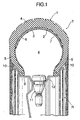
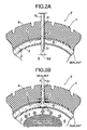
- FIG. 1, FIG. 2A and FIG. 2B show an embodiment of the present invention.
- a tubeless tire T comprising a tire body 1, an outer liner 2 fastened by vulcanization to the inner part of the tire body 1, and an inner liner 3 are mounted on a motorcycle wheel rim R.
- the outer liner 2 is fastened by vulcanization to the inner surface of a tread 4 of the tire body 1 and the left and right ends of the inner liner 3 excluding the central part are fastened by vulcanization to the inner surfaces of left and right side walls 5, 5 of the tire body 1.
- a sealant chamber 7 substantially arc-shaped in cross-section that is filled with sealant 6 is defined between the central part of the inner liner 3 and the outer liner 2 and an air chamber 8 substantially circular in cross-section is defined within the inner liner 3.
- the inner liner 3 partitioning the sealant chamber 7 and the air chamber 8 forms the partition of the present invention and is therefore composed of butyl rubber (IIR) of a 300% modulus of 60kgf/cm 2 or less.
- IIR butyl rubber
- the 300% modulus indicates the magnitude of tensile stress when a material is extended to 300%, with materials having a smaller 300% modulus being more flexible.
- the rim R is equipped with an annular rim body 9 extending in a circumferential direction of the tire T, and a pair of flanges 10, 10, extending radially outwards in a widthwise direction from both ends of the rim body 9, for supporting the inner periphery of the tire body 1.
- An air valve 11 for filling the air chamber 8 with air is supported so as to pass through an air valve attachment section 12 formed at one location in the circumferential direction of the rim body 9.
- the puncture 4 1 only contracts slightly after the nail N is pulled out because the tread 4 of the tire body 1 is formed of resilient rubber.
- the rubber of the outer liner 2 is flexible compared to the rubber of the tread 4, but the outer liner 2 is thin and is fastened to the inner surface of the tread 4 so as to be integrally formed with the tread 4.
- the puncture 2 1 in the outer liner 2 therefore also only contracts slightly after removal of the nail N.
- the inner liner 3 is made of flexible rubber of a 300% modulus of 60kgf/cm 2 or less, the puncture 3 1 rapidly contracts after the nail N is withdrawn so as to be of a diameter substantially smaller than the diameter of the nail N.
- Table 1 shows measurements of the diameter of punctures formed in the inner liner 3 when a tire (comparative example) fitted with an inner liner 3 of a 300% modulus exceeding 60kgf/cm 2 and a tire (embodiment) fitted with an inner liner 3 of a 300% modulus of 60kgf/cm 2 or less are pierced by two types of pins for nails of diameters of 3mm and 5mm. It can therefore be understood that the diameter of the puncture is reduced with the embodiment fitted with an inner liner 3 of flexible rubber of a 300% modulus of 60kgf/cm 2 or less, compared with the comparative example.
- Comparative Example 1 Comparative Example 2
- Example 1 300% Modulus (kgf/cm 2 ) 100 80 60 40 Extension at Time of Rupture (%) 300 450 550 650
- Table 2 shows investigation of the extent to which air leaks from the air chamber 8 when punctures are made in tires with pins acting as nails of various diameters.
- a liner (of a 300% modulus of 100kgf/cm 2 ) for preventing air from passing is fastened to the inner surface of a tire body of a typical tubeless tire that does not contain sealant.
- an inner liner 3 of a 300% modulus of 80kgf/cm 2 is fastened to a tire of the structure shown in FIG. 1.
- inner liners 3 of 300% moduli of 60kgf/cm 2 and 40kgf/cm 2 are fastened to the tire of the structure of FIG. 1.
- the effectiveness of preventing the leaking of air is improved as the 300% modulus is reduced, i.e. as the rubber of the inner liner 3 becomes more flexible, so that leaking of air can be effectively prevented even if the diameter of the pin causing the puncture is increased.
- This effectiveness is particularly striking for examples 1 and 2 where the 300% modulus is 60kgf/cm 2 or less.
- the outer liner 2 is fastened to the inner surface of the tread 4 of the tire body 1, but the present invention can also be applied to a tire T that does not have an outer liner 2.
- the material for the inner liner 3 is by no means limited to butyl rubber (IIR).
- the sealant-containing tire according to the present invention is applicable to a two-wheeled motor vehicle and further to other types of vehicles, e.g., a bus, a truck or an automobile.
Landscapes
- Engineering & Computer Science (AREA)
- Mechanical Engineering (AREA)
- Tires In General (AREA)
Abstract
Description
| Puncture Diameter (Pin Diameter; 3mm) | Puncture Diameter (Pin Diameter; 5mm) | |
| Comparative Example | 2.0 mm | 2.0 to 3.0 mm |
| Embodiment | 1.5 mm | 1.5 to 2.0 mm |
| Comparative Example 1 | Comparative Example 2 | Example 1 | Example 2 | |
| 300% Modulus (kgf/cm2) | 100 | 80 | 60 | 40 |
| Extension at Time of Rupture (%) | 300 | 450 | 550 | 650 |
| Tensile Stress at time of Rupture (kgf/cm2) | 100 | 150 | 120 | 100 |
| Pin Diameter; 2 mm | ○ | ○ | ○ | ○ |
| Pin Diameter; 3 mm | Δ | ○ | ○ | ○ |
| Pin Diameter; 4 mm | X | Δ | ○ | ○ |
| Pin Diameter; 5 mm | X | X | ○ | ○ |
| Pin Diameter; 6 mm | X | X | Δ | ○ |
| Pin Diameter; 7 mm | X | X | X | Δ |
| ○; Air leakage stopped rapidly. Δ; Air leakage stopped in stages. X; Air leakage not stopped. |
Claims (1)
- A sealant-containing tire with an annular sealant chamber (7) filled with sealant (6) formed at an inner surface of a tread (4) of a tire body (1), and with the sealant chamber (7) and an air chamber (8) being partitioned by a partition (3),
characterized in that the partition (3) is formed of a material of a 300% modulus of 60kgf/cm2 or less.
Applications Claiming Priority (3)
| Application Number | Priority Date | Filing Date | Title |
|---|---|---|---|
| JP12886399 | 1999-05-10 | ||
| JP11128863A JP2000318406A (en) | 1999-05-10 | 1999-05-10 | Tire with sealant |
| PCT/JP2000/002521 WO2000068028A1 (en) | 1999-05-10 | 2000-04-18 | Tire containing sealing agent |
Publications (3)
| Publication Number | Publication Date |
|---|---|
| EP1201461A1 true EP1201461A1 (en) | 2002-05-02 |
| EP1201461A4 EP1201461A4 (en) | 2006-07-05 |
| EP1201461B1 EP1201461B1 (en) | 2009-10-07 |
Family
ID=14995239
Family Applications (1)
| Application Number | Title | Priority Date | Filing Date |
|---|---|---|---|
| EP00917341A Expired - Lifetime EP1201461B1 (en) | 1999-05-10 | 2000-04-18 | Tire containing sealing agent |
Country Status (12)
| Country | Link |
|---|---|
| US (1) | US7004217B1 (en) |
| EP (1) | EP1201461B1 (en) |
| JP (1) | JP2000318406A (en) |
| KR (1) | KR100567566B1 (en) |
| CN (1) | CN100357091C (en) |
| BR (1) | BR0010487A (en) |
| CA (1) | CA2373023C (en) |
| DE (1) | DE60043111D1 (en) |
| ES (1) | ES2332702T3 (en) |
| TR (1) | TR200103224T2 (en) |
| TW (1) | TW477754B (en) |
| WO (1) | WO2000068028A1 (en) |
Cited By (2)
| Publication number | Priority date | Publication date | Assignee | Title |
|---|---|---|---|---|
| DE102005049526A1 (en) * | 2005-10-17 | 2007-04-19 | MÜLLER, Ralf | Puncture-proof tires |
| DE102010026582A1 (en) | 2010-07-08 | 2012-01-12 | Ralf Müller | Sealant for puncture-proof tires |
Families Citing this family (9)
| Publication number | Priority date | Publication date | Assignee | Title |
|---|---|---|---|---|
| WO2004016413A1 (en) * | 2002-07-16 | 2004-02-26 | Kosuke Nagaya | Structure having fluid sealed therein capable of preventing fluid leakage and method of leakage prevention |
| WO2005009763A1 (en) * | 2003-07-28 | 2005-02-03 | The Yokohama Rubber Co.,Ltd. | Pneumatic tire |
| US8617333B2 (en) * | 2007-09-20 | 2013-12-31 | The Goodyear Tire & Rubber Company | Pneumatic tire having built-in sealant layer and preparation thereof |
| US8316903B2 (en) * | 2007-10-01 | 2012-11-27 | The Goodyear Tire & Rubber Company | Pneumatic tire having built-in sealant layer and preparation thereof |
| EP3124508A1 (en) | 2015-07-27 | 2017-02-01 | ARLANXEO Deutschland GmbH | Sealing gels, method for their preparation as well as their use in sealing compositions for self-sealing tires |
| EP3354703A1 (en) | 2017-01-26 | 2018-08-01 | ARLANXEO Deutschland GmbH | Delayed sealing compounds for self-sealing tyres |
| EP3354704A1 (en) | 2017-01-26 | 2018-08-01 | ARLANXEO Deutschland GmbH | Extended sealing gels, process for production thereof and use thereof in sealing compounds for self-sealing tyres |
| CN112292259B (en) | 2018-06-13 | 2023-09-26 | 阿朗新科德国有限责任公司 | Sealing compound for self-sealing tires |
| JP2020006804A (en) * | 2018-07-09 | 2020-01-16 | 本田技研工業株式会社 | Vehicular wheel |
Family Cites Families (16)
| Publication number | Priority date | Publication date | Assignee | Title |
|---|---|---|---|---|
| US3042098A (en) * | 1958-07-01 | 1962-07-03 | Us Rubber Co | Puncture-sealant composition and tubeless pneumatic tire containing same |
| US3563294A (en) * | 1968-07-02 | 1971-02-16 | Alex Chien | Puncture-sealing band |
| US3565151A (en) | 1968-10-16 | 1971-02-23 | Armstrong Rubber Co | Puncture-sealant tire |
| CA987211A (en) | 1973-05-03 | 1976-04-13 | Roy J. Emerson | Puncture sealing means for pneumatic tires |
| GB1541382A (en) * | 1976-06-07 | 1979-02-28 | Yokohama Rubber Co Ltd | Puncture sealant for a tubeless pneumatic tyre |
| FR2425335A1 (en) * | 1978-05-10 | 1979-12-07 | Michelin & Cie | PNEUMATIC CONTAINING A GASKET OF PERFORATION CLOSURE |
| US4453992A (en) | 1980-08-06 | 1984-06-12 | The General Tire & Rubber Company | Method of making a pneumatic tire having a lubricant-containing pocket integrally formed therein |
| US4539344A (en) * | 1981-08-31 | 1985-09-03 | Rockcor, Inc. | Thermally stable sealant composition |
| US4502520A (en) * | 1984-04-02 | 1985-03-05 | The Goodyear Tire & Rubber Company | Pneumatic tire having air retention innerliner |
| US4756337A (en) * | 1986-02-24 | 1988-07-12 | Royston Laboratories, Inc. | Gasline repair kit |
| CN2131729Y (en) * | 1992-08-08 | 1993-05-05 | 楼玉刚 | Outer tyre with protective liner |
| BR9501066A (en) * | 1994-03-21 | 1995-10-17 | Goodyear Tire & Rubber | Rubber tire with an integral inner lining of a sulfur-cured rubber compound |
| JP3497281B2 (en) | 1995-06-02 | 2004-02-16 | 本田技研工業株式会社 | Method for manufacturing tire with seal liquid layer |
| CN1057487C (en) * | 1996-05-07 | 2000-10-18 | 戴建进 | Method and device for manufacturing tires with elastic sealant |
| JPH09309974A (en) * | 1996-05-21 | 1997-12-02 | Yokohama Rubber Co Ltd:The | Tubeless liner rubber composition |
| CN2295624Y (en) * | 1997-08-07 | 1998-10-28 | 贾海安 | Self mended tyre and adhesive paste for mending tyre |
-
1999
- 1999-05-10 JP JP11128863A patent/JP2000318406A/en active Pending
-
2000
- 2000-04-12 TW TW089106822A patent/TW477754B/en not_active IP Right Cessation
- 2000-04-18 ES ES00917341T patent/ES2332702T3/en not_active Expired - Lifetime
- 2000-04-18 WO PCT/JP2000/002521 patent/WO2000068028A1/en not_active Ceased
- 2000-04-18 CN CNB00807366XA patent/CN100357091C/en not_active Expired - Fee Related
- 2000-04-18 KR KR1020017014278A patent/KR100567566B1/en not_active Expired - Fee Related
- 2000-04-18 CA CA002373023A patent/CA2373023C/en not_active Expired - Fee Related
- 2000-04-18 DE DE60043111T patent/DE60043111D1/en not_active Expired - Lifetime
- 2000-04-18 US US09/926,485 patent/US7004217B1/en not_active Expired - Fee Related
- 2000-04-18 TR TR2001/03224T patent/TR200103224T2/en unknown
- 2000-04-18 EP EP00917341A patent/EP1201461B1/en not_active Expired - Lifetime
- 2000-04-18 BR BR0010487-6A patent/BR0010487A/en not_active Application Discontinuation
Cited By (4)
| Publication number | Priority date | Publication date | Assignee | Title |
|---|---|---|---|---|
| DE102005049526A1 (en) * | 2005-10-17 | 2007-04-19 | MÜLLER, Ralf | Puncture-proof tires |
| WO2007045435A1 (en) * | 2005-10-17 | 2007-04-26 | Mueller Ralf | Puncture-proof tire |
| DE102010026582A1 (en) | 2010-07-08 | 2012-01-12 | Ralf Müller | Sealant for puncture-proof tires |
| WO2012004362A1 (en) | 2010-07-08 | 2012-01-12 | Mueller Ralf | Sealant for puncture-proof tyres |
Also Published As
| Publication number | Publication date |
|---|---|
| JP2000318406A (en) | 2000-11-21 |
| BR0010487A (en) | 2002-02-13 |
| CN100357091C (en) | 2007-12-26 |
| KR20020010644A (en) | 2002-02-04 |
| DE60043111D1 (en) | 2009-11-19 |
| ES2332702T3 (en) | 2010-02-11 |
| EP1201461B1 (en) | 2009-10-07 |
| CA2373023C (en) | 2004-10-05 |
| EP1201461A4 (en) | 2006-07-05 |
| CN1350493A (en) | 2002-05-22 |
| KR100567566B1 (en) | 2006-04-05 |
| TR200103224T2 (en) | 2002-04-22 |
| TW477754B (en) | 2002-03-01 |
| CA2373023A1 (en) | 2000-11-16 |
| WO2000068028A1 (en) | 2000-11-16 |
| US7004217B1 (en) | 2006-02-28 |
Similar Documents
| Publication | Publication Date | Title |
|---|---|---|
| US7004217B1 (en) | Tire containing sealing agent | |
| HU177085B (en) | Tyre and wheel rim structure | |
| JPH10250309A (en) | Tubeless tire and rim for bicycle | |
| CN216184253U (en) | Vehicle and embedded air bag type tire burst continuous running wheel thereof | |
| JPH09240210A (en) | Tires with tubes containing sealant | |
| JP4180373B2 (en) | Assembly formed of tire and sealing piece and method of manufacturing the same | |
| US6158489A (en) | Tube tire | |
| US20060254685A1 (en) | Tire wheel assembly and noise-reducing device | |
| EP2072278B1 (en) | A dual structure tire wheel and a method for installing it | |
| KR20210091400A (en) | A pneumatic tire | |
| US6840294B2 (en) | Run-flat tire and tire/wheel assembly | |
| JP3509351B2 (en) | Tube tires | |
| CN1130286C (en) | Preserving mold for tire inner tube joint | |
| KR100454983B1 (en) | Tire containing sealer | |
| JPH10138702A (en) | Tire and rim assembly | |
| JP2000313215A (en) | Air housing wheel for filling up tire (air in wheel) | |
| JP3554436B2 (en) | Tube tires | |
| KR200280877Y1 (en) | Tire with double air pressure safety device | |
| JP2002192923A (en) | Safety pneumatic tire | |
| KR970006276Y1 (en) | Tubeless tire for caster | |
| JP3029932U (en) | Tire structure | |
| JPH1016519A (en) | Tubeless tubeless tires | |
| JPH04286631A (en) | Pneumatic tire | |
| KR20020031374A (en) | Tire with double air pressure safety device | |
| KR960009967Y1 (en) | Sealing valve structure for automobile tires and sealing tube with sealing valve |
Legal Events
| Date | Code | Title | Description |
|---|---|---|---|
| PUAI | Public reference made under article 153(3) epc to a published international application that has entered the european phase |
Free format text: ORIGINAL CODE: 0009012 |
|
| 17P | Request for examination filed |
Effective date: 20011122 |
|
| AK | Designated contracting states |
Kind code of ref document: A1 Designated state(s): AT BE CH CY DE DK ES FI FR GB GR IE IT LI LU MC NL PT SE |
|
| RBV | Designated contracting states (corrected) |
Designated state(s): DE ES FR GB IT |
|
| A4 | Supplementary search report drawn up and despatched |
Effective date: 20060602 |
|
| 17Q | First examination report despatched |
Effective date: 20071122 |
|
| GRAP | Despatch of communication of intention to grant a patent |
Free format text: ORIGINAL CODE: EPIDOSNIGR1 |
|
| GRAS | Grant fee paid |
Free format text: ORIGINAL CODE: EPIDOSNIGR3 |
|
| GRAA | (expected) grant |
Free format text: ORIGINAL CODE: 0009210 |
|
| RAP1 | Party data changed (applicant data changed or rights of an application transferred) |
Owner name: HONDA GIKEN KOGYO KABUSHIKI KAISHA |
|
| RIN1 | Information on inventor provided before grant (corrected) |
Inventor name: YAMAGIWA, TOSHIO |
|
| AK | Designated contracting states |
Kind code of ref document: B1 Designated state(s): DE ES FR GB IT |
|
| REG | Reference to a national code |
Ref country code: GB Ref legal event code: FG4D |
|
| REF | Corresponds to: |
Ref document number: 60043111 Country of ref document: DE Date of ref document: 20091119 Kind code of ref document: P |
|
| REG | Reference to a national code |
Ref country code: ES Ref legal event code: FG2A Ref document number: 2332702 Country of ref document: ES Kind code of ref document: T3 |
|
| PGFP | Annual fee paid to national office [announced via postgrant information from national office to epo] |
Ref country code: GB Payment date: 20100223 Year of fee payment: 11 |
|
| PGFP | Annual fee paid to national office [announced via postgrant information from national office to epo] |
Ref country code: ES Payment date: 20100428 Year of fee payment: 11 |
|
| PLBE | No opposition filed within time limit |
Free format text: ORIGINAL CODE: 0009261 |
|
| STAA | Information on the status of an ep patent application or granted ep patent |
Free format text: STATUS: NO OPPOSITION FILED WITHIN TIME LIMIT |
|
| 26N | No opposition filed |
Effective date: 20100708 |
|
| PGFP | Annual fee paid to national office [announced via postgrant information from national office to epo] |
Ref country code: FR Payment date: 20110426 Year of fee payment: 12 Ref country code: DE Payment date: 20110413 Year of fee payment: 12 |
|
| PGFP | Annual fee paid to national office [announced via postgrant information from national office to epo] |
Ref country code: IT Payment date: 20110420 Year of fee payment: 12 |
|
| GBPC | Gb: european patent ceased through non-payment of renewal fee |
Effective date: 20110418 |
|
| PG25 | Lapsed in a contracting state [announced via postgrant information from national office to epo] |
Ref country code: GB Free format text: LAPSE BECAUSE OF NON-PAYMENT OF DUE FEES Effective date: 20110418 |
|
| REG | Reference to a national code |
Ref country code: FR Ref legal event code: ST Effective date: 20121228 |
|
| REG | Reference to a national code |
Ref country code: DE Ref legal event code: R119 Ref document number: 60043111 Country of ref document: DE Effective date: 20121101 |
|
| PG25 | Lapsed in a contracting state [announced via postgrant information from national office to epo] |
Ref country code: FR Free format text: LAPSE BECAUSE OF NON-PAYMENT OF DUE FEES Effective date: 20120430 Ref country code: IT Free format text: LAPSE BECAUSE OF NON-PAYMENT OF DUE FEES Effective date: 20120418 |
|
| REG | Reference to a national code |
Ref country code: ES Ref legal event code: FD2A Effective date: 20131029 |
|
| PG25 | Lapsed in a contracting state [announced via postgrant information from national office to epo] |
Ref country code: ES Free format text: LAPSE BECAUSE OF NON-PAYMENT OF DUE FEES Effective date: 20110419 |
|
| PG25 | Lapsed in a contracting state [announced via postgrant information from national office to epo] |
Ref country code: DE Free format text: LAPSE BECAUSE OF NON-PAYMENT OF DUE FEES Effective date: 20121101 |