EP1201346A1 - Torch for gas shielderd arc welding using consumable electrode - Google Patents
Torch for gas shielderd arc welding using consumable electrode Download PDFInfo
- Publication number
- EP1201346A1 EP1201346A1 EP00309378A EP00309378A EP1201346A1 EP 1201346 A1 EP1201346 A1 EP 1201346A1 EP 00309378 A EP00309378 A EP 00309378A EP 00309378 A EP00309378 A EP 00309378A EP 1201346 A1 EP1201346 A1 EP 1201346A1
- Authority
- EP
- European Patent Office
- Prior art keywords
- gas
- welding
- torch
- cylinder
- internal cylinder
- Prior art date
- Legal status (The legal status is an assumption and is not a legal conclusion. Google has not performed a legal analysis and makes no representation as to the accuracy of the status listed.)
- Granted
Links
Images


Classifications
-
- B—PERFORMING OPERATIONS; TRANSPORTING
- B23—MACHINE TOOLS; METAL-WORKING NOT OTHERWISE PROVIDED FOR
- B23K—SOLDERING OR UNSOLDERING; WELDING; CLADDING OR PLATING BY SOLDERING OR WELDING; CUTTING BY APPLYING HEAT LOCALLY, e.g. FLAME CUTTING; WORKING BY LASER BEAM
- B23K9/00—Arc welding or cutting
- B23K9/24—Features related to electrodes
- B23K9/28—Supporting devices for electrodes
- B23K9/29—Supporting devices adapted for making use of shielding means
- B23K9/291—Supporting devices adapted for making use of shielding means the shielding means being a gas
- B23K9/295—Supporting devices adapted for making use of shielding means the shielding means being a gas using consumable wire electrodes
Definitions
- the present invention relates to a torch for gas shielded arc welding using a consumable electrode. More particularly, the invention pertains to a welding torch used therefor and well suited for titanium welding.
- Articles of stainless steel are bonded to one another by means of welding such as arc welding with a covered electrode, TIG (tungsten inert gas) welding, MIG (metal inert gas) welding, electron beam welding or the like.
- TIG tungsten inert gas
- MIG metal inert gas
- the above-mentioned TIG welding is of limited productivity because of a limited current load on a tungsten electrode.
- gas shielded arc welding in which a consumable electrode is used for the reason that a current load can surpassingly be enhanced when welding is performed with a melting electrode.
- the aforesaid gas shielded arc welding using a consumable electrode is exemplified by MIG welding, MAG (metal active gas) welding and CO 2 (carbon dioxide) gas shielded arc welding.
- MIG welding an inert gas such as argon gas is used as a shielding gas.
- MAG welding use is made, as a shielding gas, of a mixed gas in which an inert gas is mixed with a slight amount of oxygen gas or carbon dioxide gas.
- CO 2 gas shielded arc welding carbon dioxide gas is used. Since argon gas is expensive while carbon dioxide gas is inexpensive, the MAG welding is advantageous, and CO 2 gas shielded arc welding is further advantageous from the aspect of production cost.
- the MIG welding, MAG welding and CO 2 gas shielded arc welding are similar to one another with respect to electrode melting and interception of outside air with a shielding gas. It being so, the term "gas shielded arc welding using a consumable electrode" is used as such, or as the case may be, referred simply as "MIG welding" hereinafter.
- Torch 100 for MIG welding is a widely used and typical one comprising: a torch body 104 equipped with a wire guide cylinder 103 which guides a welding wire 102 that is fed downward in FIG.4 at a prescribed feed rate by means of feed rollers 101, 101; a gas nozzle 105 fitted to the torch body 104 in such a manner as to surround the wire guide cylinder 103; and a shielding gas passageway 107 for feeding a shielding gas in a gas passageway 106 formed between the wire guide cylinder 103 and the gas nozzle 105.
- reference numerals 112 and 113 denote a molten pool and deposited metal, respectively.
- an inert gas is fed in the gas passageway 106 through the shielding gas passageway 107, and is ejected through the lower end of the gas passageway 106, namely the opening at the lower end of the gas nozzle 105 as shown by arrows 1 ⁇ ,1 ⁇ , so that the discharge arcs 111 are enclosed by the inert gas thus ejected so as to prevent outside air (oxygen) from reaching the molten pool 112.
- gas shielding gas shielding
- shielding gas the gas used therefor
- FIG.5 illustrating a problem with the conventional MIG welding.
- the weld base metal 110 as illustrated in FIG.5 causes a surface oxide 114 although being in a slight amount to sometimes generate in the vicinity of the deposited metal.
- the surface oxide 114 is generated in stainless steel, and inter alia markedly in titanium which is an active metal more prone to combine with oxygen.
- the discharged arcs 111 rock towards the surface oxide 114.
- the rocking phenomenon which is termed “wandering phenomenon”, instabilizes welding itself when it arises.
- the inert gas constitutes so-called “turbulent flow”.
- the resultant turbulent flow catches up circumferential gases, thereby causing outside air to be caught up therein with the result that the increased feed rate thereof is not recognized as a considerably effective countermeasure.
- the MAG welding can be said to be an improved method over the MIG welding from the viewpoint that a slight amount (several percent) of oxygen gas or carbon dioxide gas is mixed in the inert gas in order to suppress the phenomenon.
- welding argon gas is mixed with, for example, 2.0 % to 3.0 % of oxygen gas.
- the amount of the oxygen gas when being less than 2.0 %, causes the wandering phenomenon, whereas the amount, when being more than 3.0 %, brings about the unfavorable result that the surface oxide 114 becomes more prone to be generated. It is therefore obliged to strictly regulate the mixing proportion of the gas to be added thereto (oxygen gas). For this reason, the burden on a welding worker is greatly increased, or it becomes necessary to adopt a mixing unit equipped with a precise control unit. Accordingly, it follows that the MAG welding results in high welding cost as compared with the MIG welding.
- a torch for gas shielded arc welding using a consumable electrode comprising: a torch body having a wire guide cylinder for guiding a welding wire; an internal cylinder fitted to the torch body in such a manner as to surround the wire guide cylinder; an external cylinder fitted to the internal cylinder in such a manner as to surround the internal cylinder; a first shielding gas feed route for feeding a shielding gas in a first gas passageway formed between the wire guide cylinder and the internal cylinder; and a second shielding gas feed route for feeding the shielding gas in a second gas passageway formed between the internal cylinder and the external cylinder.
- the above-mentioned torch has a tip configuration of double pipe structure composed of an internal cylinder and an external cylinder, and a shielding gas is fed in a first gas passageway formed in the internal cylinder, and in a second gas passageway formed between the internal cylinder and the external cylinder.
- a shielding gas is fed in a first gas passageway formed in the internal cylinder, and in a second gas passageway formed between the internal cylinder and the external cylinder.
- the internal cylinder is composed of a large diameter portion which is fitted to the torch body, and a small diameter portion at an end which is connected to the large diameter portion via a tapered tubular portion. It is made possible to increase the flow velocity of the shielding gas blown off through the internal cylinder by such construction that the small diameter portion is formed at an end and also to fit the cylinder to an existing torch body by forming the large diameter portion at the root portion thereof.
- a porous member is installable between the internal cylinder and external cylinder (second gas passageway) so as to rectify the shielding gas passing through the second gas passageway.
- the porous member is exemplified by a stainless steel wire mesh, which is located in the second gas passageway and substantially fills the passageway.
- the shielding gas is decelerated and dispersed through the stainless steel wire mesh, and hence is blown off at a low velocity in a rectified state, thereby eliminating the worry of external air being caught up in the shielding gas feed.
- the tip of the external cylinder recedes fom the tip of the internal cylinder so as to direct the shielding gas passing through the second gas passageway radially outwardly, and enable penetrating exterior air to be swept away in a radially outwardly direction.
- a torch 10 for gas shielded arc welding using a consumable electrode (hereinafter referred to as "welding torch 10") comprises a torch body 20 equipped with a wire guide cylinder 21 for guiding a welding wire 11; an internal cylinder 30 fitted to the torch body 20 in such a manner as to surround the wire guide cylinder 20;and an external cylinder 40 fitted to the internal cylinder 30 in such a manner as to surround the internal cylinder 30.
- the internal cylinder 30 is a stepped cylinder composed of a large diameter portion 32 equipped with a female screw 31 to be threaded onto the torch body 20 and a male thread 35 formed on the outer periphery of itself, a tapered tubular portion 33 and a small diameter portion 34 each being connected in series.
- the inside diameter D2 of the small diameter portion 34 is approximately halved compared with the inside diameter D1 of the large diameter portion 32.
- D1 and D2 are set to be 18mm and 10mm, respectively.
- the external cylinder 40 is in the form of a cylinder which has a female screw 41 provided on its root portion, a second shielding gas feed route 42, and a bellmouth 43 provided on its tip.
- the bellmouth 43 signifies a smoothly widened portion and is adopted in the opening of a western bell.
- the inside diameter D3 of the external cylinder 40 is slightly larger than the diameter D1.
- D1 and D3 are set to be 18mm and about 20mm, respectively.
- FIG.2 illustrates a welding torch 10 which is assembled by threading the internal cylinder 30 onto the torch body 20 and threading the external cylinder 40 onto the internal cylinder 30.
- Reference numeral 50 denotes a porous member which is filled in between the internal cylinder 30 and the external cylinder 40, and preferably a stainless steel wire mesh in the form of metallic scrubbing brush.
- the assembly leads to a space which is formed between the wire guide cylinder 21 and the internal cylinder 30, and is termed first gas passageway 51.
- a shielding gas is fed into the resultant first gas passageway 51 via a first shielding gas feed route 23.
- a space which is formed between the internal cylinder 30 and the external cylinder 40 is termed a second gas passageway 52.
- a shielding gas is fed into the resultant second gas passageway 52 via a second shielding gas feed route 42, which is constituted so that the shielding gas is blown at right angles with the second gas passageway 52. The right angles cause the shielding gas which flows in the second gas passageway 52 via the second shielding gas feed route 42 to change its direction by 90 degrees, during which time the gas is moderately dispersed and almost uniformly passed through the second gas passageway 52.
- the present embodiment is, at least in one way, characterized in that the tip of the external cylinder 40 is allowed to recede from the tip of the internal cylinder 30 by a prescribed distance L, which however, can be adjusted by turning the external cylinder 40 against the internal cylinder 30 so as to alter the quantity of threading and which is suitably in the range of 5mm to 8mm.
- the welding torch 10 according to the present embodiment is almost the same as the conventional MIG welding torch 100 in respect of external configuration, Accordingly, the welding work using the welding torch 10 can be carried out in a similar way as previous.
- the welding torch has a tip configuration of double pipe structure composed of an internal cylinder 30 and an external cylinder 40, and a shielding gas is fed in the first gas passageway 51 formed in the internal cylinder 30, and in the second gas passageway 52 formed between the internal cylinder 30 and the external cylinder 40.
- a shielding gas is fed in the first gas passageway 51 formed in the internal cylinder 30, and in the second gas passageway 52 formed between the internal cylinder 30 and the external cylinder 40.
- the feed rate of a shielding gas in a conventional welding torch is set on an index of 100
- the feed rate Q1 in the first shielding gas feed route 23 is set on an index of 50
- the feed rate Q2 in the second shielding gas feed route 42 is set also on an index of 50.
- the cross sectional area thereat is one quarter of that of a conventional welding torch, and the blowing off speed v1 from the internal cylinder 30 is roughly doubled compared with a conventional speed because of the cross sectional area being about 1/4 and the flow rate being about 1/4.
- the intercepting performance of the first shielding gas layer 54 as illustrated in FIG.3 is doubled compared with conventional performance.
- the enhanced cooling performance enables molten metal to be rapidly solidified and also to prevent oxidation.
- the enhanced flow velocity of the first shielding gas layer 54 could possibly have lead to the inclusion of surrounding air (oxygen) being caught up in the gas flow.
- the first shielding gas layer 54 is surrounded by the second shielding gas layer 55, which prevents outside air from penetrating. Such constitution and function eliminate the worry of external air being caught up in the gas feed.
- the blowing off speed v2 of the shielding gas which constitutes the second shielding gas layer 55 is made to be two thirds of a conventional blowing off speed. Since as mentioned hereinbefore, the second shielding gas layer 55 achieves the primary interception of outside air, the blowing off speed v2 thereof, when decreased to such an extent, air no longer becomes mixed up in the protective gases and is therefore out of the question in function.
- the shielding gas passing through the second gas passageway 52 possibly brings about channelling or unevenness of the flow.
- a porous member is allowed to intervene in the second gas passageway 52 so as to rectify the shielding gas passing therethrough.
- the shielding gas is allowed to flow into the second gas passageway 52 at right angles in particular, and thus is uniformized. The foregoing effect contributes to the rectification of the shielding gas passing through the second gas passageway 52.
- the welding torch 10 according to the present invention is of such constitution as enabling the rectification of the shielding gas passing through the second gas passageway 52.
- shielding gas feed rates Q1 and Q2 are each nothing more than a specific example. Thus it may be determined by means of demonstration tests whether (Q1 + Q2) is set on a gas flow rate same as that of a conventional flow rate or larger or smaller than that.
- pure argon gas is satisfactorily usable as a shielding gas.
- the MAG welding necessitates strict control of a mixing proportion due to the addition of oxygen gas, thus unfavorably increasing the welding cost.
- pure argon gas need not be controlled in mixing proportion, thereby enabling to suppress the welding cost.
- the present invention led to success in enhancing the welding quality as well as suppressing the welding cost.
- the present invention led to success in assuring favorable weldability for titanium and stainless steel in spite of the use of pure argon gas as a shielding gas.
- a mixed gas wherein pure oxygen gas is mixed in an inert gas as shielding gas for the welding torch according to the present invention.
- the welding torch according to the present invention is usable in any of the MIG welding, MAG welding and CO 2 gas shielded arc welding.
- the configuration of the internal cylinder 30 may be optionally selected, and when it is a straight pipe, the external cylinder 40 may be a stepped cylinder. However, it is more preferable in this case that the internal cylinder 30 be a stepped cylinder, since otherwise the flow velocity of the first shielding gas layer would be lower and besides, the external appearance of the welding torch 10 would be different from that of a conventional torch.
- the porous member stainless steel wire mesh is optimum because of its easy availability.
- the porous member may be selected from among porous ceramics, perforated plates, metallic mesh and the like irrespective of the type and kind, provided that it functions as a rectifying plate.
- the present invention also extends to a method of welding employing two concentric flows of shielding gas for shielding the arc from exterior air, in which the innermost flow of gas flows faster and is surrounded by the outmost flow of gas.
Landscapes
- Engineering & Computer Science (AREA)
- Physics & Mathematics (AREA)
- Plasma & Fusion (AREA)
- Mechanical Engineering (AREA)
- Arc Welding In General (AREA)
Abstract
Description
- The present invention relates to a torch for gas shielded arc welding using a consumable electrode. More particularly, the invention pertains to a welding torch used therefor and well suited for titanium welding.
- Articles of stainless steel are bonded to one another by means of welding such as arc welding with a covered electrode, TIG (tungsten inert gas) welding, MIG (metal inert gas) welding, electron beam welding or the like. Articles of titanium which are more enriched in activity than stainless steel articles are bonded to one another by welding such as TIG welding, MIG welding, electron beam welding or the like.
- In the case of welding with a covered electrode, it is impossible to completely prevent ambient air (oxygen) from mixing in a deposited metal, whereby the deposited metal is made brittle. As an alternative, it is preferred to employ TIG welding by which welding is carried out with a tungsten (W) electrode, while the electrode is shielded from outside air with a shielding gas.
- However, the above-mentioned TIG welding is of limited productivity because of a limited current load on a tungsten electrode. Thus, it becomes necessary to employ gas shielded arc welding in which a consumable electrode is used for the reason that a current load can surpassingly be enhanced when welding is performed with a melting electrode. The aforesaid gas shielded arc welding using a consumable electrode is exemplified by MIG welding, MAG (metal active gas) welding and CO2 (carbon dioxide) gas shielded arc welding. In the MIG welding, an inert gas such as argon gas is used as a shielding gas. In the MAG welding, use is made, as a shielding gas, of a mixed gas in which an inert gas is mixed with a slight amount of oxygen gas or carbon dioxide gas. In CO2 gas shielded arc welding, carbon dioxide gas is used. Since argon gas is expensive while carbon dioxide gas is inexpensive, the MAG welding is advantageous, and CO2 gas shielded arc welding is further advantageous from the aspect of production cost. The MIG welding, MAG welding and CO2 gas shielded arc welding are similar to one another with respect to electrode melting and interception of outside air with a shielding gas. It being so, the term "gas shielded arc welding using a consumable electrode" is used as such, or as the case may be, referred simply as "MIG welding" hereinafter.
- MIG welding has recently been advanced in its improvement and commercialization. Thus, proposals were made for instance, on a torch structure in Japanese Patent Laid-Open Publication No. HEI-10-128546 entitled "TORCH FOR ARC WELDING", and on torch cleaning technology in Japanese Patent Laid-Open Publication No. HEI-9-085448 entitled "TORCH FOR WELDING". Nevertheless, it has been proved that even by the use of the above-mentioned welding torch, the fundamental problems as described hereunder still remain unsolved.
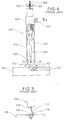
- Hereinafter, description will be given as to the principle of a conventional torch with reference to FIG.4 hereof. Torch 100 for MIG welding is a widely used and typical one comprising: a
torch body 104 equipped with awire guide cylinder 103 which guides awelding wire 102 that is fed downward in FIG.4 at a prescribed feed rate by means offeed rollers gas nozzle 105 fitted to thetorch body 104 in such a manner as to surround thewire guide cylinder 103; and a shieldinggas passageway 107 for feeding a shielding gas in agas passageway 106 formed between thewire guide cylinder 103 and thegas nozzle 105. - In this arrangement, when welding voltage is applied between the
welding wire 102 and aweld base metal 110, discharged arcs 111 are scattered and produce arc heat therebetween, by which heat theweld base metal 110 as well as thewelding wire 102 melt away. In the Figure,reference numerals - At this time, an inert gas is fed in the
gas passageway 106 through the shieldinggas passageway 107, and is ejected through the lower end of thegas passageway 106, namely the opening at the lower end of thegas nozzle 105 as shown byarrows 1 ○,1 ○, so that the discharge arcs 111 are enclosed by the inert gas thus ejected so as to prevent outside air (oxygen) from reaching themolten pool 112. The interception of outside air with a gas is termed "gas shielding", and the gas used therefor is termed "shielding gas". - Next, reference is made to FIG.5 illustrating a problem with the conventional MIG welding. When the
MIG welding torch 100 is moved from front to back, theweld base metal 110 as illustrated in FIG.5 causes asurface oxide 114 although being in a slight amount to sometimes generate in the vicinity of the deposited metal. Thesurface oxide 114 is generated in stainless steel, and inter alia markedly in titanium which is an active metal more prone to combine with oxygen. - It being so, the discharged arcs 111 rock towards the
surface oxide 114. The rocking phenomenon, which is termed "wandering phenomenon", instabilizes welding itself when it arises. When the feed rate of the inert gas is increased as a countermeasure against the generation of thesurface oxide 114, the inert gas constitutes so-called "turbulent flow". The resultant turbulent flow catches up circumferential gases, thereby causing outside air to be caught up therein with the result that the increased feed rate thereof is not recognized as a considerably effective countermeasure. - With regard to the aforesaid wandering phenomenon, the MAG welding can be said to be an improved method over the MIG welding from the viewpoint that a slight amount (several percent) of oxygen gas or carbon dioxide gas is mixed in the inert gas in order to suppress the phenomenon.
- In the MAG, welding argon gas is mixed with, for example, 2.0 % to 3.0 % of oxygen gas. The amount of the oxygen gas, when being less than 2.0 %, causes the wandering phenomenon, whereas the amount, when being more than 3.0 %, brings about the unfavorable result that the
surface oxide 114 becomes more prone to be generated. It is therefore obliged to strictly regulate the mixing proportion of the gas to be added thereto (oxygen gas). For this reason, the burden on a welding worker is greatly increased, or it becomes necessary to adopt a mixing unit equipped with a precise control unit. Accordingly, it follows that the MAG welding results in high welding cost as compared with the MIG welding. - It is therefore an object of the invention to provide a technique which enables welding technically comparable to MAG welding at a welding cost competitive with MIG welding, and also a technique which enhances the quality of welding, in the case of welding stainless steel and titanium that are more prone to combine with oxygen.
- To attain the foregoing object, according to the present invention, there is provided a torch for gas shielded arc welding using a consumable electrode, comprising: a torch body having a wire guide cylinder for guiding a welding wire; an internal cylinder fitted to the torch body in such a manner as to surround the wire guide cylinder; an external cylinder fitted to the internal cylinder in such a manner as to surround the internal cylinder; a first shielding gas feed route for feeding a shielding gas in a first gas passageway formed between the wire guide cylinder and the internal cylinder; and a second shielding gas feed route for feeding the shielding gas in a second gas passageway formed between the internal cylinder and the external cylinder.
- The above-mentioned torch has a tip configuration of double pipe structure composed of an internal cylinder and an external cylinder, and a shielding gas is fed in a first gas passageway formed in the internal cylinder, and in a second gas passageway formed between the internal cylinder and the external cylinder. Thus, primary interception of outside air is put into practice with a second shielding gas layer blown off through the second gas passageway arranged on the outer side, and complete interception of outside air is put into practice with the first shielding gas layer blown off through the first gas passageway arranged on the inner side.
- Preferably, the internal cylinder is composed of a large diameter portion which is fitted to the torch body, and a small diameter portion at an end which is connected to the large diameter portion via a tapered tubular portion. It is made possible to increase the flow velocity of the shielding gas blown off through the internal cylinder by such construction that the small diameter portion is formed at an end and also to fit the cylinder to an existing torch body by forming the large diameter portion at the root portion thereof.
- Also preferably, a porous member is installable between the internal cylinder and external cylinder (second gas passageway) so as to rectify the shielding gas passing through the second gas passageway. The porous member is exemplified by a stainless steel wire mesh, which is located in the second gas passageway and substantially fills the passageway. The shielding gas is decelerated and dispersed through the stainless steel wire mesh, and hence is blown off at a low velocity in a rectified state, thereby eliminating the worry of external air being caught up in the shielding gas feed.
- Also preferably, the tip of the external cylinder recedes fom the tip of the internal cylinder so as to direct the shielding gas passing through the second gas passageway radially outwardly, and enable penetrating exterior air to be swept away in a radially outwardly direction.
- A preferred embodiment of the present invention will be described in detail below, by way of example only, with reference to the accompanying drawings, in which:
- FIG.1 is an exploded view showing a torch for gas shielded arc welding using a consumable electrode according to the present invention;
- FIG.2 is a side view illustrating, partially in section, the welding torch as assembled;
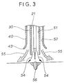
- FIG.3 is an enlarged partial view showing operation of the welding torch;
- FIG.4 is a view showing the principle of conventional MIG welding; and
- FIG.5 is a view showing a problem in conventional MIG welding.
-
- The following description is merely exemplary in nature and is in no way intended to limit the invention, its application or uses.
- As illustrated in FIG.1, a
torch 10 for gas shielded arc welding using a consumable electrode (hereinafter referred to as "welding torch 10") comprises atorch body 20 equipped with awire guide cylinder 21 for guiding awelding wire 11; aninternal cylinder 30 fitted to thetorch body 20 in such a manner as to surround thewire guide cylinder 20;and anexternal cylinder 40 fitted to theinternal cylinder 30 in such a manner as to surround theinternal cylinder 30. - The
torch body 20 being equivalent to a marketed torch product comprises acylinder body 24 which is equipped with agas chamber 22 and a first shieldinggas feed route 23 and which is threaded asmale screw 25; acone portion 27 which hasorifices 26 of a small diameter and is extended from themale screw 25 ; and thewire guide cylinder 21 which is extended from thecone portion 27. - The
internal cylinder 30 is a stepped cylinder composed of alarge diameter portion 32 equipped with afemale screw 31 to be threaded onto thetorch body 20 and amale thread 35 formed on the outer periphery of itself, a taperedtubular portion 33 and asmall diameter portion 34 each being connected in series. Therein, the inside diameter D2 of thesmall diameter portion 34 is approximately halved compared with the inside diameter D1 of thelarge diameter portion 32. For example, D1 and D2 are set to be 18mm and 10mm, respectively. - The
external cylinder 40 is in the form of a cylinder which has afemale screw 41 provided on its root portion, a second shieldinggas feed route 42, and abellmouth 43 provided on its tip. Thebellmouth 43 signifies a smoothly widened portion and is adopted in the opening of a western bell. Therein, the inside diameter D3 of theexternal cylinder 40 is slightly larger than the diameter D1. For instance, D1 and D3 are set to be 18mm and about 20mm, respectively. - FIG.2 illustrates a
welding torch 10 which is assembled by threading theinternal cylinder 30 onto thetorch body 20 and threading theexternal cylinder 40 onto theinternal cylinder 30.Reference numeral 50 denotes a porous member which is filled in between theinternal cylinder 30 and theexternal cylinder 40, and preferably a stainless steel wire mesh in the form of metallic scrubbing brush. - The assembly leads to a space which is formed between the
wire guide cylinder 21 and theinternal cylinder 30, and is termedfirst gas passageway 51. A shielding gas is fed into the resultantfirst gas passageway 51 via a first shieldinggas feed route 23. Likewise, a space which is formed between theinternal cylinder 30 and theexternal cylinder 40 is termed asecond gas passageway 52. A shielding gas is fed into the resultantsecond gas passageway 52 via a second shieldinggas feed route 42, which is constituted so that the shielding gas is blown at right angles with thesecond gas passageway 52. The right angles cause the shielding gas which flows in thesecond gas passageway 52 via the second shieldinggas feed route 42 to change its direction by 90 degrees, during which time the gas is moderately dispersed and almost uniformly passed through thesecond gas passageway 52. - The present embodiment is, at least in one way, characterized in that the tip of the
external cylinder 40 is allowed to recede from the tip of theinternal cylinder 30 by a prescribed distance L, which however, can be adjusted by turning theexternal cylinder 40 against theinternal cylinder 30 so as to alter the quantity of threading and which is suitably in the range of 5mm to 8mm. - Importance should be attached, as being clear from comparison with FIG.4, to that the outside diameter of the
external cylinder 40 is almost the same as the outside diameter of theconventional gas nozzle 105. As a result, thewelding torch 10 according to the present embodiment is almost the same as the conventionalMIG welding torch 100 in respect of external configuration, Accordingly, the welding work using thewelding torch 10 can be carried out in a similar way as previous. - In what follows, some description will be given as to the function of the welding torch having the above constitution.
- As illustrated in FIG.3, the welding torch has a tip configuration of double pipe structure composed of an
internal cylinder 30 and anexternal cylinder 40, and a shielding gas is fed in thefirst gas passageway 51 formed in theinternal cylinder 30, and in thesecond gas passageway 52 formed between theinternal cylinder 30 and theexternal cylinder 40. Thus, primary interception of outside air is put into practice with a secondshielding gas layer 55 that is blown off through thesecond gas passageway 52 arranged on the outer side, and secondary interception of outside air is put into practice with the firstshielding gas layer 54 that is blown off through thefirst gas passageway 51 arranged on the inner side, thereby enabling complete interception of outside air. - More specifically, when the feed rate of a shielding gas in a conventional welding torch is set on an index of 100, the feed rate Q1 in the first shielding
gas feed route 23 is set on an index of 50, and the feed rate Q2 in the second shieldinggas feed route 42 is set also on an index of 50. - Since the diameter of the
internal cylinder 30 is roughly halved at the tip thereof, the cross sectional area thereat is one quarter of that of a conventional welding torch, and the blowing off speed v1 from theinternal cylinder 30 is roughly doubled compared with a conventional speed because of the cross sectional area being about 1/4 and the flow rate being about 1/4. As a result, it follows that the intercepting performance of the firstshielding gas layer 54 as illustrated in FIG.3 is doubled compared with conventional performance. - In addition, it is made possible to throttle discharge arc and also enhance cooling performance by tapering the tip of the
internal cylinder 30 so as to enhance the flow velocity of the shielding gas. That is, the enhanced cooling performance enables molten metal to be rapidly solidified and also to prevent oxidation. In general, the enhanced flow velocity of the firstshielding gas layer 54 could possibly have lead to the inclusion of surrounding air (oxygen) being caught up in the gas flow. However, in the present invention, the firstshielding gas layer 54 is surrounded by the secondshielding gas layer 55, which prevents outside air from penetrating. Such constitution and function eliminate the worry of external air being caught up in the gas feed. - Turning back to FIG.2, since the
second gas passageway 52 has a cross sectional area about three times that of thefirst gas passageway 51, the blowing off speed v2 of the shielding gas which constitutes the second shielding gas layer 55 (see FIG.3) is made to be two thirds of a conventional blowing off speed. Since as mentioned hereinbefore, the secondshielding gas layer 55 achieves the primary interception of outside air, the blowing off speed v2 thereof, when decreased to such an extent, air no longer becomes mixed up in the protective gases and is therefore out of the question in function. - However, decreased flow rate of the shielding gas passing through the
second gas passageway 52 possibly brings about channelling or unevenness of the flow. As a countermeasure thereagainst in the present embodiment, a porous member is allowed to intervene in thesecond gas passageway 52 so as to rectify the shielding gas passing therethrough. By virtue of such rectification, it is possible to preclude channelling or unevenness of the flow, and realize the working effect on the primary interception of outside air. In the second shieldinggas feed route 42, the shielding gas is allowed to flow into thesecond gas passageway 52 at right angles in particular, and thus is uniformized. The foregoing effect contributes to the rectification of the shielding gas passing through thesecond gas passageway 52. It being so, thewelding torch 10 according to the present invention is of such constitution as enabling the rectification of the shielding gas passing through thesecond gas passageway 52. - Moreover, by allowing the tip of the
external cylinder 40 to recede from the tip of theinternal cylinder 30 by a prescribed distance L1, it is made possible to direct the shielding gas passing through thesecond gas passageway 52 radially outwardly instead of radially inwardly and into theinternal cylinder 30, and at the same time to sweep away penetrating outside air radially outwardly. Likewise, by forming the opening of theexternal cylinder 40 with a bellmouth portion, it is made possible to direct the shielding gas passing through thesecond gas passageway 52 radially outwardly and to sweep away penetrating exterior air in the same way,in the radially outwardly direction. - By the functions described above, as illustrated in FIG.3, it is made possible to prevent the generation of a surface oxide in the vicinity of the deposited metal and that of a wandering phenomenon, thereby enabling to stabilize the arc and proceed with favorable welding work.
- In addition, the above-mentioned shielding gas feed rates Q1 and Q2 are each nothing more than a specific example. Thus it may be determined by means of demonstration tests whether (Q1 + Q2) is set on a gas flow rate same as that of a conventional flow rate or larger or smaller than that.
- Furthermore, pure argon gas is satisfactorily usable as a shielding gas. The MAG welding necessitates strict control of a mixing proportion due to the addition of oxygen gas, thus unfavorably increasing the welding cost. As opposed to the foregoing, pure argon gas need not be controlled in mixing proportion, thereby enabling to suppress the welding cost.
- That is to say, by virtue of the features of the present invention, it is made possible to prevent the generation of a wandering phenomenon at the same level as in the MAG welding in spite of using pure argon gas as is the case with the MIG welding and also to suppress catching up of outside air. Consequently, the present invention led to success in enhancing the welding quality as well as suppressing the welding cost.
- As described hereinbefore, the present invention led to success in assuring favorable weldability for titanium and stainless steel in spite of the use of pure argon gas as a shielding gas. However, it is acceptable to use a mixed gas wherein pure oxygen gas is mixed in an inert gas as shielding gas for the welding torch according to the present invention. Saying it differently, the welding torch according to the present invention is usable in any of the MIG welding, MAG welding and CO2 gas shielded arc welding.
- The configuration of the
internal cylinder 30 may be optionally selected, and when it is a straight pipe, theexternal cylinder 40 may be a stepped cylinder. However, it is more preferable in this case that theinternal cylinder 30 be a stepped cylinder, since otherwise the flow velocity of the first shielding gas layer would be lower and besides, the external appearance of thewelding torch 10 would be different from that of a conventional torch. - As the porous member, stainless steel wire mesh is optimum because of its easy availability. However, the porous member may be selected from among porous ceramics, perforated plates, metallic mesh and the like irrespective of the type and kind, provided that it functions as a rectifying plate.
- The present invention also extends to a method of welding employing two concentric flows of shielding gas for shielding the arc from exterior air, in which the innermost flow of gas flows faster and is surrounded by the outmost flow of gas.
Claims (8)
- A torch for gas shielded arc welding using a consumable electrode, comprising:characterised in that said torch further comprises:a torch body (20) having a wire guide cylinder (21) for guiding a welding wire (11);an internal cylinder (30) fitted to said torch body in such a manner as to surround said wire guide cylinder; anda first shielding gas feed route (23) for feeding a shielding gas in a first gas passageway (51) formed between said wire guide cylinder and said internal cylinder,an external cylinder (40) fitted to said internal cylinder in such a manner as to surround said internal cylinder; anda second shielding gas feed route (42) for feeding the shielding gas in a second gas passageway (52) formed between said internal cylinder (30) and said external cylinder (40).
- The torch of claim 1, characterised in that said internal cylinder (30) is composed of a large diameter portion (32) which is fitted to the torch body (20), and a small diameter portion (34) at an end thereof which is connected to said large diameter portion via a tapered tubular portion (33).
- The torch of claim 1 or 2, characterised in that said second gas passageway (52) includes a porous member (50) disposed therein for rectifying the shielding gas passing gas passing through said second gas passageway.
- The torch of claim 1, 2 or 3, characterised in that said external cylinder (40) has a tip receded a predetermined distance from a tip of said internal cylinder (30).
- A method of welding an active metal which is prone to combine with oxygen using a torch as claimed in any preceding claim.
- A method of welding as claimed in claim 5 which comprises metal inert gas (MIG) welding.
- A method of welding as claimed in claim 5 which comprises metal active gas (MAG) welding.
- A method of welding as claimed in claim 5 which comprises CO2 gas shielded arc welding.
Priority Applications (4)
| Application Number | Priority Date | Filing Date | Title |
|---|---|---|---|
| JP11118352A JP2000312972A (en) | 1999-04-26 | 1999-04-26 | Welding gas shielded arc welding torch |
| US09/691,901 US6392184B1 (en) | 1999-04-26 | 2000-10-19 | Torch for gas shielded arc welding using consumable electrode |
| EP00309378A EP1201346B1 (en) | 1999-04-26 | 2000-10-25 | Torch for gas shielderd arc welding using consumable electrode |
| DE2000625314 DE60025314T2 (en) | 2000-10-25 | 2000-10-25 | Inert gas arc welding torch with consuming electrode |
Applications Claiming Priority (3)
| Application Number | Priority Date | Filing Date | Title |
|---|---|---|---|
| JP11118352A JP2000312972A (en) | 1999-04-26 | 1999-04-26 | Welding gas shielded arc welding torch |
| US09/691,901 US6392184B1 (en) | 1999-04-26 | 2000-10-19 | Torch for gas shielded arc welding using consumable electrode |
| EP00309378A EP1201346B1 (en) | 1999-04-26 | 2000-10-25 | Torch for gas shielderd arc welding using consumable electrode |
Publications (2)
| Publication Number | Publication Date |
|---|---|
| EP1201346A1 true EP1201346A1 (en) | 2002-05-02 |
| EP1201346B1 EP1201346B1 (en) | 2006-01-04 |
Family
ID=27223565
Family Applications (1)
| Application Number | Title | Priority Date | Filing Date |
|---|---|---|---|
| EP00309378A Expired - Lifetime EP1201346B1 (en) | 1999-04-26 | 2000-10-25 | Torch for gas shielderd arc welding using consumable electrode |
Country Status (3)
| Country | Link |
|---|---|
| US (1) | US6392184B1 (en) |
| EP (1) | EP1201346B1 (en) |
| JP (1) | JP2000312972A (en) |
Cited By (7)
| Publication number | Priority date | Publication date | Assignee | Title |
|---|---|---|---|---|
| EP1563939A1 (en) * | 2004-02-11 | 2005-08-17 | Rolls-Royce Plc | A welding torch and shield |
| EP1607164A1 (en) * | 2004-06-17 | 2005-12-21 | Illinois Tool Works Inc. | Nozzle assembly for a TIG welding torch with a front nozzle and a rear nozzle for fixing there between a porous disc |
| DE102006056047A1 (en) * | 2006-11-28 | 2008-05-29 | Messer Group Gmbh | Welding torch for inert gas welding |
| EP2199006A1 (en) | 2008-12-16 | 2010-06-23 | EWM Hightec Welding GmbH | Burner for an arc welding device |
| DE10314278B4 (en) * | 2003-03-29 | 2011-05-05 | Tbi Industries Gmbh | MIG / MAG welding torch |
| EP2380692A1 (en) * | 2010-04-23 | 2011-10-26 | Dinse G.m.b.H. | Protective gas connections or coatings with internal smoke extraction |
| EP2865477A1 (en) * | 2013-10-22 | 2015-04-29 | Linde Aktiengesellschaft | Method and device for for welding metal using protective gas |
Families Citing this family (21)
| Publication number | Priority date | Publication date | Assignee | Title |
|---|---|---|---|---|
| US20040245233A1 (en) * | 2002-06-05 | 2004-12-09 | Dorsch Thomas James | Low cost titanium welding method |
| CN1305629C (en) * | 2005-03-11 | 2007-03-21 | 南京晨光集团有限责任公司 | Consumable electrode automatic wolding gun |
| FR2887163B1 (en) * | 2005-06-15 | 2008-10-17 | Framatome Anp Sas | WELDING TORCH. |
| JP4842665B2 (en) * | 2005-12-05 | 2011-12-21 | 株式会社ダイヘン | Two-electrode arc welding method for high alloy steel |
| US20070187461A1 (en) * | 2006-01-30 | 2007-08-16 | Honeywell International, Inc. | Welding shielding dam for automated welding of impellers and blisks |
| US7456370B2 (en) * | 2006-01-30 | 2008-11-25 | Honeywell International Inc. | Welding shield and flexible skirt for automated welding |
| JP2008260055A (en) * | 2007-04-16 | 2008-10-30 | Fujikura Ltd | Welding observation device |
| JP5031537B2 (en) * | 2007-12-07 | 2012-09-19 | 新日本製鐵株式会社 | Plasma surface heating apparatus and plasma surface heating method for continuous cast slab |
| US8927901B2 (en) * | 2008-03-17 | 2015-01-06 | Alcoa Inc. | Buried-arc welding of metal work pieces with through-the-arc seam tracking |
| US8324524B2 (en) * | 2008-03-26 | 2012-12-04 | Taiyo Nippon Sanso Corporation | Plasma welding process and outer gas for use in the plasma welding process |
| US20100276397A1 (en) * | 2009-05-01 | 2010-11-04 | Baker Hughes Incorporated | Electrically isolated gas cups for plasma transfer arc welding torches, and related methods |
| JP5901111B2 (en) * | 2010-10-07 | 2016-04-06 | 大陽日酸株式会社 | Welding gas and plasma welding method |
| JP5287962B2 (en) * | 2011-01-26 | 2013-09-11 | 株式会社デンソー | Welding equipment |
| JP5178963B2 (en) * | 2011-02-15 | 2013-04-10 | 大陽日酸株式会社 | Welding torch and adapter kit |
| US20120261388A1 (en) * | 2011-03-25 | 2012-10-18 | Illinois Tool Works Inc. | Systems and devices for power commutation in welding torches |
| JP2013086136A (en) * | 2011-10-19 | 2013-05-13 | Taiyo Nippon Sanso Corp | Tig welding method for ferritic stainless steel plate |
| JP6373098B2 (en) * | 2014-07-08 | 2018-08-15 | 日鉄住金パイプライン&エンジニアリング株式会社 | Welding device with double nozzle |
| CN105618895B (en) * | 2016-01-06 | 2018-04-03 | 江苏烁石焊接科技有限公司 | A kind of coaxial 3D printing device of silk powder pneumoelectric arc |
| JP6661415B2 (en) * | 2016-03-04 | 2020-03-11 | 株式会社神戸製鋼所 | Welding torch |
| CN112139492B (en) * | 2019-06-28 | 2022-08-16 | 南京理工大学 | Adjustable compound vibration material disk of super-strong steel normal position silk powder composition |
| JP2024077972A (en) * | 2022-11-29 | 2024-06-10 | 住友重機械ハイマテックス株式会社 | Gas shielding method, dual gas nozzle and external nozzle outer cylinder |
Citations (3)
| Publication number | Priority date | Publication date | Assignee | Title |
|---|---|---|---|---|
| FR1433400A (en) * | 1965-01-23 | 1966-04-01 | Metalinox | Diffuser filter for welding oxidizable metals |
| DE7928898U1 (en) * | 1979-10-11 | 1980-10-16 | Kohlensaeurewerke C.G. Rommenhoeller Gmbh, 3490 Bad Driburg-Herste | Welding gun for a welding process that uses CO2 and argon |
| JPS59218282A (en) * | 1983-05-25 | 1984-12-08 | Hitachi Ltd | Welding torch for automatic welding machine |
Family Cites Families (9)
| Publication number | Priority date | Publication date | Assignee | Title |
|---|---|---|---|---|
| US2758186A (en) * | 1952-10-21 | 1956-08-07 | Westinghouse Electric Corp | Deep penetration gas shielded arc welding process |
| US2859328A (en) * | 1954-04-29 | 1958-11-04 | Air Reduction | Gas shielded arc welding |
| US2919341A (en) * | 1955-07-18 | 1959-12-29 | Union Carbide Corp | Multi-gas sigma welding |
| US3270178A (en) * | 1965-08-03 | 1966-08-30 | Harnischfeger Corp | Welding nozzle |
| US3473002A (en) * | 1965-09-10 | 1969-10-14 | Mitsubishi Heavy Ind Ltd | Triply shielded arc welding method |
| FR2278445A1 (en) * | 1974-05-23 | 1976-02-13 | Kobe Steel Ltd | PROCESS FOR WELDING ALUMINUM AND ALUMINUM ALLOYS IN A HORIZONTAL POSITION |
| US4166940A (en) * | 1976-03-26 | 1979-09-04 | Combustion Engineering, Inc. | Dual-gas shielding method |
| JPH0985448A (en) | 1995-09-25 | 1997-03-31 | Suzuki Motor Corp | Welding torch |
| JPH10128546A (en) | 1996-10-31 | 1998-05-19 | Suzuki Motor Corp | Arc welding torch |
-
1999
- 1999-04-26 JP JP11118352A patent/JP2000312972A/en active Pending
-
2000
- 2000-10-19 US US09/691,901 patent/US6392184B1/en not_active Expired - Fee Related
- 2000-10-25 EP EP00309378A patent/EP1201346B1/en not_active Expired - Lifetime
Patent Citations (3)
| Publication number | Priority date | Publication date | Assignee | Title |
|---|---|---|---|---|
| FR1433400A (en) * | 1965-01-23 | 1966-04-01 | Metalinox | Diffuser filter for welding oxidizable metals |
| DE7928898U1 (en) * | 1979-10-11 | 1980-10-16 | Kohlensaeurewerke C.G. Rommenhoeller Gmbh, 3490 Bad Driburg-Herste | Welding gun for a welding process that uses CO2 and argon |
| JPS59218282A (en) * | 1983-05-25 | 1984-12-08 | Hitachi Ltd | Welding torch for automatic welding machine |
Non-Patent Citations (1)
| Title |
|---|
| PATENT ABSTRACTS OF JAPAN vol. 9, no. 92 (M - 373)<1815> 20 April 1985 (1985-04-20) * |
Cited By (9)
| Publication number | Priority date | Publication date | Assignee | Title |
|---|---|---|---|---|
| DE10314278B4 (en) * | 2003-03-29 | 2011-05-05 | Tbi Industries Gmbh | MIG / MAG welding torch |
| EP1563939A1 (en) * | 2004-02-11 | 2005-08-17 | Rolls-Royce Plc | A welding torch and shield |
| EP1607164A1 (en) * | 2004-06-17 | 2005-12-21 | Illinois Tool Works Inc. | Nozzle assembly for a TIG welding torch with a front nozzle and a rear nozzle for fixing there between a porous disc |
| US7329826B2 (en) | 2004-06-17 | 2008-02-12 | Illinois Tool Works Inc. | Nozzle assembly for welding torch |
| DE102006056047A1 (en) * | 2006-11-28 | 2008-05-29 | Messer Group Gmbh | Welding torch for inert gas welding |
| EP2097206A1 (en) * | 2006-11-28 | 2009-09-09 | Messer Group GmbH | Welding torch for gas-shielded welding |
| EP2199006A1 (en) | 2008-12-16 | 2010-06-23 | EWM Hightec Welding GmbH | Burner for an arc welding device |
| EP2380692A1 (en) * | 2010-04-23 | 2011-10-26 | Dinse G.m.b.H. | Protective gas connections or coatings with internal smoke extraction |
| EP2865477A1 (en) * | 2013-10-22 | 2015-04-29 | Linde Aktiengesellschaft | Method and device for for welding metal using protective gas |
Also Published As
| Publication number | Publication date |
|---|---|
| US6392184B1 (en) | 2002-05-21 |
| JP2000312972A (en) | 2000-11-14 |
| EP1201346B1 (en) | 2006-01-04 |
Similar Documents
| Publication | Publication Date | Title |
|---|---|---|
| EP1201346B1 (en) | Torch for gas shielderd arc welding using consumable electrode | |
| CA2133199C (en) | Welding assembly for feeding powdered filler material into a torch | |
| US20060289394A1 (en) | TIG welding or braze welding with metal transfer via a liquid bridge | |
| JP4803355B2 (en) | Consumable electrode type gas shielded arc welding method and welding torch used therefor | |
| JP7134681B2 (en) | Powder ejection guide for plasma powder deposition and plasma powder deposition torch | |
| JPH07204854A (en) | High speed gas shield arc welding apparatus and method | |
| JP7260451B2 (en) | Insert tips, insert caps, plasma welding torches and plasma welding equipment | |
| JP6589016B1 (en) | Laser processing head and laser processing apparatus | |
| JP7609734B2 (en) | Shield jig and gas shielded arc welding device | |
| JPH0550247A (en) | Double gas shielded metal-arc welding method | |
| JPH01162578A (en) | Powder plasma overlay welding torch | |
| JP2016163903A (en) | Torch nozzle for narrow groove and welding method | |
| JPS6096375A (en) | Plasma torch for powder build-up welding | |
| EP4338880B1 (en) | Welding or additive manufacturing torch with shield gas screen | |
| JP3457978B2 (en) | Powder plasma arc overlay welding method and plasma torch | |
| JP2001025875A (en) | Plasma arc circumferential welding method for steel pipes | |
| KR102259499B1 (en) | diffuser corn for welding torch | |
| JP2000312973A (en) | Plasma cutting method, apparatus and plasma torch | |
| JP2014108458A (en) | Plasma GMA welding torch | |
| US20040159640A1 (en) | Plasma powder welding device and its welding method | |
| JPH0436786B2 (en) | ||
| JP2008238242A (en) | Joining method and plasma torch usable for this method | |
| JP2007054872A (en) | Welding torch for gas-encapsulated arc welding | |
| JPH11291049A (en) | Welding torch | |
| JPS62176682A (en) | Arcing method using monoconsumable electrode |
Legal Events
| Date | Code | Title | Description |
|---|---|---|---|
| PUAI | Public reference made under article 153(3) epc to a published international application that has entered the european phase |
Free format text: ORIGINAL CODE: 0009012 |
|
| AK | Designated contracting states |
Kind code of ref document: A1 Designated state(s): AT BE CH CY DE DK ES FI FR GB GR IE IT LI LU MC NL PT SE Kind code of ref document: A1 Designated state(s): DE GB IT |
|
| AX | Request for extension of the european patent |
Free format text: AL;LT;LV;MK;RO;SI |
|
| 17P | Request for examination filed |
Effective date: 20020523 |
|
| AKX | Designation fees paid |
Free format text: DE GB IT |
|
| 17Q | First examination report despatched |
Effective date: 20041007 |
|
| GRAP | Despatch of communication of intention to grant a patent |
Free format text: ORIGINAL CODE: EPIDOSNIGR1 |
|
| GRAS | Grant fee paid |
Free format text: ORIGINAL CODE: EPIDOSNIGR3 |
|
| GRAA | (expected) grant |
Free format text: ORIGINAL CODE: 0009210 |
|
| AK | Designated contracting states |
Kind code of ref document: B1 Designated state(s): DE GB IT |
|
| PG25 | Lapsed in a contracting state [announced via postgrant information from national office to epo] |
Ref country code: IT Free format text: LAPSE BECAUSE OF FAILURE TO SUBMIT A TRANSLATION OF THE DESCRIPTION OR TO PAY THE FEE WITHIN THE PRESCRIBED TIME-LIMIT;WARNING: LAPSES OF ITALIAN PATENTS WITH EFFECTIVE DATE BEFORE 2007 MAY HAVE OCCURRED AT ANY TIME BEFORE 2007. THE CORRECT EFFECTIVE DATE MAY BE DIFFERENT FROM THE ONE RECORDED. Effective date: 20060104 |
|
| REG | Reference to a national code |
Ref country code: GB Ref legal event code: FG4D |
|
| REF | Corresponds to: |
Ref document number: 60025314 Country of ref document: DE Date of ref document: 20060330 Kind code of ref document: P |
|
| PGFP | Annual fee paid to national office [announced via postgrant information from national office to epo] |
Ref country code: DE Payment date: 20061019 Year of fee payment: 7 |
|
| PGFP | Annual fee paid to national office [announced via postgrant information from national office to epo] |
Ref country code: GB Payment date: 20061025 Year of fee payment: 7 |
|
| PGFP | Annual fee paid to national office [announced via postgrant information from national office to epo] |
Ref country code: IT Payment date: 20061031 Year of fee payment: 7 |
|
| PLBE | No opposition filed within time limit |
Free format text: ORIGINAL CODE: 0009261 |
|
| STAA | Information on the status of an ep patent application or granted ep patent |
Free format text: STATUS: NO OPPOSITION FILED WITHIN TIME LIMIT |
|
| 26N | No opposition filed |
Effective date: 20061005 |
|
| GBPC | Gb: european patent ceased through non-payment of renewal fee |
Effective date: 20071025 |
|
| PG25 | Lapsed in a contracting state [announced via postgrant information from national office to epo] |
Ref country code: DE Free format text: LAPSE BECAUSE OF NON-PAYMENT OF DUE FEES Effective date: 20080501 |
|
| PG25 | Lapsed in a contracting state [announced via postgrant information from national office to epo] |
Ref country code: GB Free format text: LAPSE BECAUSE OF NON-PAYMENT OF DUE FEES Effective date: 20071025 |
|
| PG25 | Lapsed in a contracting state [announced via postgrant information from national office to epo] |
Ref country code: IT Free format text: LAPSE BECAUSE OF NON-PAYMENT OF DUE FEES Effective date: 20071025 |